Coherent collapses of dipolar Bose-Einstein condensates for different trap geometries
Abstract
We experimentally investigate the collapse dynamics of dipolar Bose-Einstein condensates of chromium atoms in different harmonic trap geometries, from prolate to oblate. The evolutions of the condensates in the unstable regime are compared to three-dimensional simulations of the Gross-Pitaevskii equation including three-body losses. In order to probe the phase coherence of collapsed condensates, we induce the collapse in several condensates simultaneously and let them interfere.
pacs:
03.75.Kk, 03.75.Lm1 Introduction
A collapse is a fast, collective phenomenon consisting in the destruction of a multi-particle system happening abruptly on the time scale which governs the “usual dynamics”. One example is the gravitational core collapse initiating a supernova. Happening within milliseconds, its duration is negligible compared to any of the time scales related to the preceding fusion stages [1].
In contrary to a supernova, where the experimenter is condemned to be an observer only, Bose-Einstein condensates (BECs) are excellent adjustable systems. Tailoring both the external confining potential and the interaction between the atoms allows to control the properties of the condensate. It is not only an ideal system to study questions from condensed matter physics [2, 3, 4, 5, 6, 7, 8, 9], but the dynamics of a collapse as well.
Collapsing condensates were first observed in 7Li [10] and 85Rb [11]. Both systems are characterized by the contact interaction, which is described by a single parameter, the -wave scattering length . From a simple model [12] minimizing the Gross-Pitaevskii energy functional using a gaussian ansatz for the wave function, one can understand the instability threshold. The energy functional consists of three terms: (i) the kinetic energy, which, in the sub-micro Kelvin range of almost pure condensates, is equal to the quantum pressure (arising from the Heisenberg uncertainty principle in the trap potential), (ii) the harmonic trapping potential, and (iii) the interaction energy. For repulsive contact interaction () a global minimum exists, and the condensate is stable. For small enough attractive interactions (), only a local minimum exists at finite size; the condensate is metastable. Finally, for sufficiently attractive interaction the local minimum vanishes. The potential energy of the BEC can be lowered without bound by contraction. Thus, the condensate is unstable.
As the density increases, this model is too simple to describe the physics of the unstable cloud – atom losses due to three-body collisions have to be included. Being negligible at low densities, the three-body collision rate rapidly increases as the cloud shrinks. A three-body collision allows for the production of a dimer, where the third contributing atom is needed to fulfill energy and momentum conservation. The binding energy which is absorbed by the atom and the molecule in form of kinetic energy is sufficient for both to escape from the trap. Hence, instead of reaching a fully contracted “point-like” state, more and more atoms are lost, so that eventually the quantum pressure dominates over the remaining interaction energy. The dynamics inverts, the atoms accelerate outwards to the new equilibrium state. Because the three-body losses have changed the total energy, this new equilibrium state differs from the initial one.
Inducing the collapse in a condensate with non-negligible dipolar interactions changes the dynamics completely. While the contact interaction is short-range and spherically symmetric, the dipolar interaction is long-range and cylindrically symmetric (partially attractive and partially repulsive). Therefore, dipolar condensates exhibit many novel phenomena even in non-collapsing systems [13, 14, 15, 16, 17, 18, 19, 20, 21, 22, 23, 24, 25].
The anisotropy of the dipolar interaction can also be used to change the mechanism for the collapse – either driving or stabilizing the collapse: In a cigar-shaped trap with the dipoles oriented along the long axis the atoms experience predominantly the attractive part of the dipolar mean-field potential [26]. Hence, the collapse is driven by the dipolar interaction, while the contact interaction stabilizes the condensate. The instability occurs at positive scattering length. This situation is reversed if the dipoles are confined in a pancake-shaped trap. Now their dipolar interaction is essentially repulsive. The dipolar interaction stabilizes the condensate and the condensate is able to withstand negative scattering lengths for which a purely contact interacting BEC would have become unstable already [26]. The instability occurs at negative scattering length. This simple consideration strongly suggests that different trap geometries result in different collapse dynamics.
In this paper we study the collapse of a chromium condensate under the influence of magnetic dipole interaction [27, 28, 26]. After describing our experimental procedure to induce the collapse, we compare the experimental data for different trapping potentials with 3D simulations of the Gross-Pitaevskii equation (GPE) including three-body losses. We show that this model provides a good description of the experimental data. This is not clear a priori as one might expect that the collapse dynamics induces many-body quantum correlations, while the GPE is a mean-field description, not taking correlations into account. Finally, we prove that the collapsed atomic cloud contains a remnant condensate by probing its phase coherence. Although simulations for purely contact interacting BECs have shown [29] that the observed bursts and jets of a collapsing condensate should be coherent, this had not been tested experimentally to date.
2 Experimental sequence to produce collapsing dipolar condensates
In order to create a condensate dominated by the dipolar interaction, we exploit the broadest of the observed Feshbach resonances in 52Cr [30]. In the vicinity of this Feshbach resonance, the scattering length varies with the applied magnetic field as [31]
| (1) |
where G is the position of the Feshbach resonance, G is its width and is the background scattering length, with the Bohr radius. The magnetic field is directed along the -direction and determines the orientation of the dipoles. Using the experimental procedure described in [26], a condensate of approximately atoms is formed in a crossed far-detuned optical dipole trap at above the Feshbach resonance. We then shape the external confining potentials to obtain the desired ratio of the trapping frequencies by adjusting the power in the crossed dipole trap and superimposing (only for pancake-shaped traps ) an additional one-dimensional optical lattice along the -direction. The superimposed lattice is formed by two far-detuned beams (wavelength nm) crossing under a small angle (), as shown in figure 1. This results in a relatively large spacing of m between neighboring lattice sites.
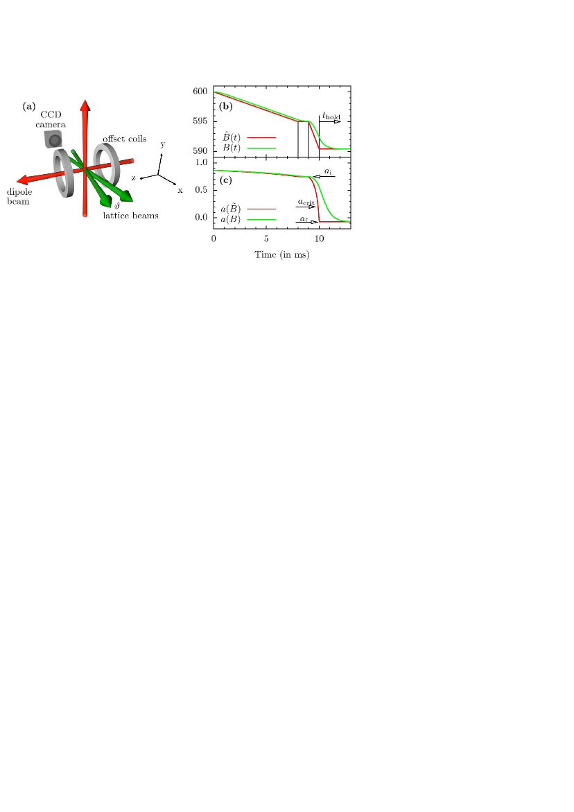
We first adiabatically ramp the current in the offset coils linearly in 8 ms to a scattering length close to the point where the collapse occurs, and wait for 1 ms for the eddy currents (mainly due to copper gaskets in our experimental chamber) to faint out. Thus, the magnetic field at the position of the atoms does not follow the ramp instantaneously, but must be calculated according to the equation
| (2) |
where is the magnetic field produced by the offset coils (changed linearly during ramps) and ms is the lifetime of the eddy currents, measured by Zeeman spectroscopy [32]. After 1 ms of waiting time at , we start a second ramp from to , where is the critical scattering length for the given trapping potential [26], so that the collapse occurs. We hold the atoms in the trap for an additional time at before releasing them and taking a time-of-flight image. In order to get the maximal absorption cross section, we split the time-of-flight into two parts: a first one, lasting 4 ms, at the magnetic field corresponding to (in order not to disturb the dynamics) and a second part, lasting again 4 ms, where the large magnetic field along is replaced by a field of 11 G along the -direction. We checked that this procedure does not disturb the image.
The observed integrated density distribution is bimodal and consists of a broad isotropic thermal cloud and an anisotropic remnant BEC (see e.g. Fig 1(b) of [32]). Because the size of the thermal cloud as well as its atom number does not depend on , it is unlikely to contribute to the collapse dynamics. In the following, we have subtracted it from the images to increase the contrast.
3 Collapse dynamics for different trap geometries
The anisotropic character of the dipolar interaction (dipoles side-by-side repel each other, while dipoles in a head-to-tail configuration attract each other) has a strong effect on the stability of a dipolar condensate: varying the geometry of the confining harmonic trap from prolate to oblate (the symmetry axis being the one along which the dipoles are aligned) stabilizes the condensate, as was demonstrated experimentally in [26]. Our previous experimental study of the collapse dynamics of a dipolar condensate [32] was restricted to an almost spherical trap; in the following we study the influence of the trap geometry on the collapse dynamics.
3.1 Prolate traps
For purely contact interacting condensates the time scale which governs the “usual dynamics” is set by the largest trap frequency. In contrast, for dipolar condensates this time scale is given by the largest radial trap frequency , because the collapse is induced in this direction [32].
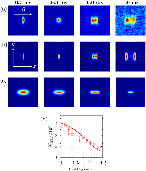
Figure 2 presents the collapse of a dipolar condensate in a very elongated prolate trap (). Here we ramp from an initial scattering length to , which lies below the critical scattering length . On the time scale of the radial trap period ms the condensate only starts to split. This is explicitly shown in figure 2 (d): The atom number does not drop “abruptly” to its final value, but instead it changes linearly on the time scale . Therefore, in the case of figure 2 we observe only a “moderate” collapse.
Each panel in figure 2 (a) and (b) presents the integrated column density of an absorption image after 8 ms of free expansion. While the upper row shows the experimental data, the lower rows is obtained from a numerical simulation of the three dimensional Gross-Pitaevskii equation
with the contact and dipolar interactions
where is the atomic mass, the magnetic permeability of vacuum, the magnetic moment of chromium, and is the angle between and the magnetic field . The imaginary term describes the atom losses. The simulations contain no free parameter, as the three-body coefficient was estimated from measurements. Details about the simulations are described in [32].
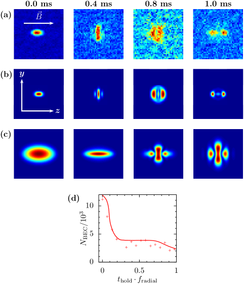
Figure 3 shows the collapse in a cigar-shaped trap with trapping frequencies Hz, corresponding to , and radial trapping period ms. We start with atoms before ramping the scattering length from to , which lies below the critical scattering length. The absorption images indicate three different stages: First, for ms, the condensate is strongly elongated along the magnetic field direction, demonstrating strong dipolar interactions [28]. Second, we observe a change of ellipticity after . This is a consequence of the radial implosion and subsequent explosion (a stable, cigar-shaped dipolar condensate does not invert its ellipticity during the free expansion [28]). Third, we observe a splitting of the condensate in axial direction as in figure 2, but now after . For longer holding times the splitting becomes more prominent, but the dynamics is already completed after half a trapping period. This is shown in figure 3 (d). The remnant atom number drops from to within this time scale. Note that, for this figure (and only this one), the simulation results agree better with the data when performed with (the results shown in figure 3 are for this value of ). This slight discrepancy is most probably due to a slow drift of the magnetic field that occurred between the data acquisition and the calibration of the scattering length (the calibration procedure, described in details in [28], requires the accumulation of a large quantity of data).
3.2 Oblate trap
As discussed, different trap geometries are expected to result in different collapse dynamics. So figures 2 and 3 have to be compared to the time evolution of an almost spherical and a pancake-shaped trap. While the collapse in an almost spherical trap is published in [32], we present the pancake-shaped trap in figure 4.
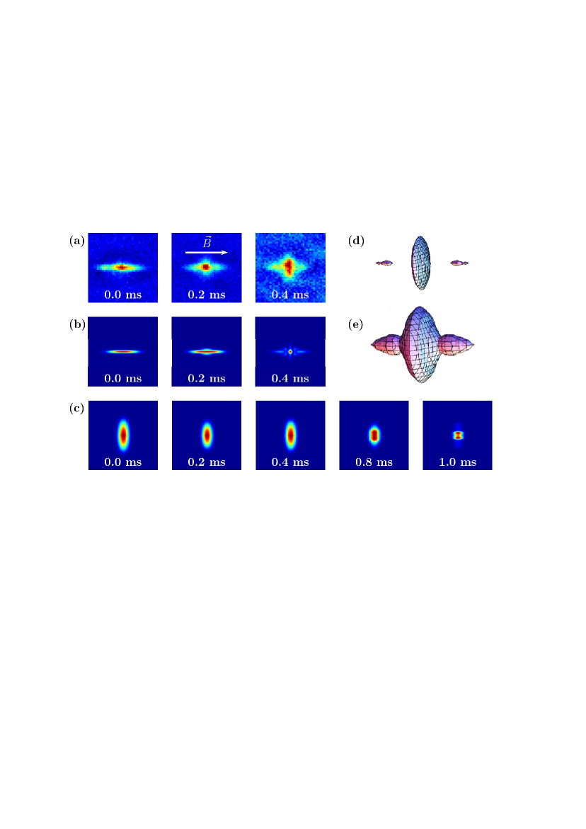
The pancake-shaped trap is formed by superimposing two additional lattice beams onto a condensate, which was produced in the crossed dipole trap, see figure 1. Depending on the non-stabilized relative phase of the two lattice beams, it is in principle possible that the condensate splits into two. Practically, we have never observed interference fringes, even at expansion times long enough, so that the fringe spacing was larger than our m resolution limit. Switching off the trapping potential immediately after finishing the magnetic field ramp results in a very elongated condensate, in agreement with the simulations (figure 4).
The cylindrical symmetry of the pancake-shaped trap allows us to recover the three-dimensional density distribution from the two-dimensional absorption image . Figure 4 (d) and (e) show isodensity surfaces for two different densities obtained from the inverse Abel transformation [33]
| (3) |
for ms, where is the Bessel function of the first kind. As in the almost spherical trap [32], the collapsed cloud exhibits a -wave symmetry. While the isodensity surface for “high” densities contains a central disc and two separated “blobs” along the symmetry axis, the three parts merge for “low” densities. Because the Abel transformation is very sensitive to noise, we cannot extract in a reliable way the kinetic energy released during the collapse from our images.
4 Testing the coherence of the collapsed cloud
By analyzing the collapse of condensates confined in different trap geometries, we showed that the survival density pattern exhibits two parts: one part, which is well described by a thermal cloud and a second part, which, due to its high optical density, we interpreted as a remnant condensate [32]. In order to confirm this interpretation, we checked the coherence of interfering condensates in the case of pancake-shaped traps.

For that purpose, we produce several condensates by superimposing the two beams for the optical lattice before finishing the evaporation to reach quantum degeneracy. Here the extension of the cloud is still large enough, so that the atoms occupy three to five adjacent lattice sites. The exact number of occupied sites changes from shot to shot, depending on the relative phase of the two lattice beams, which are not actively stabilized. After condensing, the BECs on different lattice sites have random phases with respect to each another. The single particle tunneling rate is vanishingly small (s), so that no phase coherence between adjacent sites is built up on the time scale of the experiment.
It is known [34] that the interference fringes are not washed out if few independent condensates interfere instead of only two. Taking the same trap geometry as in figure 4, but extending the time-of-flight to 18 ms, we obtain the interference patterns shown in figure 5. As expected, the absolute position of the interference fringes changes from shot to shot, but they can be clearly seen on each image.
While for holding times shorter than ms or longer than ms interference fringes with a high contrast are visible, we observe no interference fringes at the center of the two clouds for ms. A possible interpretation is as follows: For ms no collapse occurs and the observed fringes are similar to those of two point sources. For ms and ms the condensates do collapse, but this happens during the time-of-flight and after the clouds overlapped: e.g. for ms the condensates start to overlap for ms, but the collapse happens at ms. Probably this induces a complicated phase distribution in each of the condensate and integration over the line of sight washes out the interference fringes. On the other hand, if the collapse happens in-trap (e.g. for ms) the fringes are formed by the remnant condensates. Again we recover the fringes as if the atoms would belong to two coherent point sources.
5 Conclusions
We have investigated theoretically and experimentally the collapse dynamics of dipolar condensates in prolate and oblate harmonic trapping potentials. As expected, the collapse dynamics depends on the trap geometry, although the qualitative behavior is similar for different traps. The simulations containing no adjustable parameter reproduce the experimental results well. By simultaneously inducing a collapse in several condensates and let them interfere, we showed that the collapsed cloud contains a coherent remnant condensate.
A clear direction of further studies is to use the interferometric technique of section 4 to obtain experimental evidence for the vortex rings predicted in [32]. The contrast of the interference fringes is not high enough to support their evidence yet. An other interesting extension is the study of two-dimensional solitons [35, 36], which are expected to appear just above the instability threshold.
References
- [1] Woosley S E, Heger A and Weaver T A 2002 Rev. Mod. Phys. 74 1015–1071
- [2] Fattori M, Roati G, Deissler B, D’Errico C, Zaccanti M, Jona-Lasinio M, Santos L, Inguscio M and Modugno G 2008 Phys. Rev. Lett. 101 190405
- [3] Levy S, Lahoud E, Shomroni I and Steinhauer J 2007 Nature 449 579–583
- [4] Greiner M, Mandel O, Esslinger T, Hänsch T W and Bloch I 2002 Nature 415 39–44
- [5] Billy J, Josse V, Zuo Z, Bernard A, Hambrecht B, Lugan P, Clément D, Sanchez-Palencia L, Bouyer P and Aspect A 2008 Nature 453 891–894
- [6] Paredes B, Widera A, Murg V, Mandel O, Fölling S, Cirac I, Shlyapnikov G V, Hänsch T W and Bloch I 2004 Nature 29 277–281
- [7] Kinoshita T, Wenger T and Weiss D S 2004 Science 305 1125–1128
- [8] Hadzibabic Z, Krüger P, Cheneau M, Battelier B and Dalibard J 2006 Nature 441 1118–1121
- [9] Bloch I, Dalibard J and Zwerger W 2008 Rev. Mod. Phys. 80 885–964
- [10] Gerton J M, Strekalov D, Prodan I and Hulet R G 2000 Nature 408 692–695
- [11] Donley E A, Claussen N R, Cornish S L, Roberts J L, Cornell E A and Wieman C E 2001 Nature 412 295–299
- [12] Dalfovo F, Giorgini S, Pitaevskii L P and Stringari S 1999 Rev. Mod. Phys. 71 463–512
- [13] Baranov M, Dobrek L, Góral K, Santos L and Lewenstein M 2002 Physica Scripta T102 74–81
- [14] Góral K, Santos L and Lewenstein M 2002 Phys. Rev. Lett. 88 170406
- [15] Baranov M 2008 Phys. Rep. 464 71–111
- [16] Santos L, Shlyapnikov G V and Lewenstein M 2003 Phys. Rev. Lett. 90 250403
- [17] O’Dell D H J, Giovanazzi S and Eberlein C 2004 Phys. Rev. Lett. 92 250401
- [18] Ronen S, Bortolotti D C E and Bohn J L 2007 Phys. Rev. Lett. 98 030406
- [19] Dutta O and Meystre P 2007 Phys. Rev. A 75 053604
- [20] Yi S and Pu H 2006 Phys. Rev. A 73 061602R
- [21] Cooper N R, Rezayi E H and Simon S H 2005 Phys. Rev. Lett. 95 200402
- [22] Zhang J and Zhai H 2005 Phys. Rev. Lett. 95 200403
- [23] Kawaguchi Y, Saito H, and Ueda M 2006 Phys. Rev. Lett. 96 080405
- [24] Santos L and Pfau T 2006 Phys. Rev. Lett. 96 190404
- [25] Yi S and Pu H 2006 Phys. Rev. Lett. 97 020401
- [26] Koch T, Lahaye T, Metz J, Fröhlich B, Griesmaier A and Pfau T 2008 Nat. Phys. 4 218–222
- [27] Stuhler J, Griesmaier A, Koch T, Fattori M, Pfau T, Giovanazzi S, Pedri P and Santos L 2005 Phys. Rev. Lett. 95 150406
- [28] Lahaye T, Koch T, Fröhlich B, Fattori M, Metz J, Griesmaier A, Giovanazzi S and Pfau T 2007 Nature 448 672–675
- [29] Saito H and Ueda M 2002 Phys. Rev. A 65 033624
- [30] Werner J, Griesmaier A, Hensler S, Stuhler J, Pfau T, Simoni A and Tiesinga E 2005 Phys. Rev. Lett. 94 183201
- [31] Köhler T, Góral K and Julienne P S 2006 Rev. Mod. Phys. 78 1311–1361
- [32] Lahaye T, Metz J, Fröhlich B, Koch T, Meister M, Griesmaier A, Pfau T, Saito H, Kawaguchi Y and Ueda M 2008 Phys. Rev. Lett. 101 080401.
- [33] Bracewell R N 2000 The Fourier Transfrom and Its Applications (New York: McGraw-Hill)
- [34] Hadzibabic Z, Stock S, Battelier B, Bretin V and Dalibard J 2004 Phys. Rev. Lett. 93 180403
- [35] Pedri P and Santos L 2005 Phys. Rev. Lett. 95 200404
- [36] Tikhonenkov I, Malomed B A and Vardi A 2008 Phys. Rev. Lett. 100 090406