Cu/Ag EAM Potential Optimized for Heteroepitaxial Diffusion from ab initio Data
Abstract
A binary embedded-atom method (EAM) potential is optimized for Cu on Ag(111) by fitting to ab initio data. The fitting database consists of DFT calculations of Cu monomers and dimers on Ag(111), specifically their relative energies, adatom heights, and dimer separations. We start from the Mishin Cu-Ag EAM potential and first modify the Cu-Ag pair potential to match the FCC/HCP site energy difference then include Cu-Cu pair potential optimization for the entire database. The optimized EAM potential reproduce DFT monomer and dimer relative energies and geometries correctly. In trimer calculations, the potential produces the DFT relative energy between FCC and HCP trimers, though a different ground state is predicted. We use the optimized potential to calculate diffusion barriers for Cu monomers, dimers, and trimers. The predicted monomer barrier is the same as DFT, while experimental barriers for monomers and dimers are both lower than predicted here. We attribute the difference with experiment to the overestimation of surface adsorption energies by DFT and a simple correction is presented. Our results show that the optimized Cu-Ag EAM can be applied in the study of larger Cu islands on Ag(111).
pacs:
68.35.Fx,68.35.bd,68.35.Gy,71.15.PdI Introduction
Knowledge of the surface diffusion dynamics for small atom clusters is critical to understanding heteroepitaxial thin film growth. While numerous experimentsWen et al. (1994); Kellogg and Voter (1991); Bartelt et al. (1999); Antczak and Ehrlich (2007) and computer simulationsPapanicolaou et al. (1998); Montalenti and Ferrando (1999); Bogicevic (1999); Lorensen et al. (1999) have studied homogeneous systems, less is known about lattice mismatched heterogeneous systemsChirita et al. (1999); Papathanakos and Evangelakis (2002); Brune et al. (1999) and their interesting diffusion kinetics. In this study, we consider Cu on Ag(111),Morgenstern et al. (2004) a system with a lattice mismatch of 12%.Ozoliņš et al. (1998) The lattice mismatch induces strain in both the island and substrate and has been predicted to promote rapid diffusion.Hamilton (1996)
To accurately compute the energetics of surface island systems, first principle density-functional theory (DFT) calculations are preferred to empirical potentials. However, DFT methods are too computationally intensive to efficiently search the phase space of each island and accurate classical potentials are needed to characterize island diffusional dynamics. The embedded atom methodFoiles et al. (1986) (EAM) is well suited for metallic systems combining pair interactions with an atomic embedding energy term dependent on the local “electron density.” Table 1 shows that other EAM potentials were unable to reproduce DFT calculated Cu island energies and geometries on Ag(111), motivating the search for a new potential.
We optimize a new EAM potential for Cu on Ag(111) using monomer and dimer data. Section II explains the DFT and EAM calculation parameters in detail. Section III presents the procedure for the potential optimization. The energetics and diffusion results from the new EAM for monomers, dimers, and trimers are reported in Section IV. We justify the new potential for the study of small Cu islands on Ag(111) surface by comparing the calculated results to experimental and DFT values in Section V.
II Computational Details
The density-functional theory calculations are performed with vasp,Kresse and Hafner (1993); Kresse and Furthmüller (1996) a density-functional code using a plane-wave basis and ultrasoft Vanderbilt-type pseudopotentials.Vanderbilt (1990); Kresse and Hafner (1994) The local-density approximation as parametrized by Perdew and ZungerPerdew and Zunger (1981) and a plane-wave kinetic-energy cutoff of 200 eV ensures accurate treatment of the Cu and Ag potential. We treat the and states as valence, corresponding to an Ar and Kr core atomic reference configuration for Cu and Ag, respectively. The surface slab calculations used a geometry with 6 planes of Ag and 6 planes of vacuum; the -point meshes for the surface slab calculations are , with a Methfessel-Paxton smearing of 0.25 eV.
EAM energy values were computed with the lammps molecular dynamics package.Plimpton (1995) The monomer and dimer results in Table 1 are obtained using a periodic 33 cell of 6 (111) planes. The trimers are calculated with 44 periodic cells. Results presented in section IV are from 66 periodic cells, where our potential predicts a finite-size effect of less than 5meV compared to the 33 cell. Transition energy barriers are determined with nudged elastic bandMills and Jónsson (1994) calculations after initial and final states have been found through molecular dynamics or the dimer search method.Henkelman and Jónsson (1999) Attempt frequency prefactors are computed with the Vineyard formula,Vineyard (1957) taking the ratio between the product of harmonic vibrational frequencies at the initial state and the saddle point.
III Optimization Procedure
In EAM, the total energy of the system is given by
where is the pair potential interaction between atoms i and j separated by a distance of and is embedding energy of atom i in the superposition of atomic electron densities . The Mishin CuAg binary EAM potentialMishin et al. (2001); Williams et al. (2006) is described by seven functions: , , , , , , and . The Mishin EAM embedding energy functions and electron density functions are not changed in our optimization. Only the Cu-Ag and Cu-Cu pair potentials are modified to fit our DFT optimization database. We forgo modification of the Ag-Ag potential because the distance between relaxed EAM Ag(111) planes are within 3% of the relaxed DFT Ag surface.
Cu monomers and dimers are building blocks for larger islands, making them ideal choices for the optimization database. The Ag(111) surface is divided into FCC and HCP sites, depending on the atomic configuration continuing from the top two layers of Ag. For monomers, the single Cu atom rests at either a FCC or HCP site. For dimers, four different configuration of the Cu pair can be formed, FCC-FCC (FF), HCP-HCP (HH), and two types of FCC-HCP (FH and FH). The two FH dimers (c.f. Fig. 5) are differentiated by their neighboring Ag atoms, the two triangles of Ag neighbors can share a side (FH), or share a corner (FH). The optimization database consists of the relative DFT energies between FCC and HCP monomers and all four dimers, geometric information on the heights of monomers and dimers above the Ag surface, and the Cu-Cu separation length. We minimize the total root-mean-square (rms) error of the energy differences and balance that with the total rms error of the heights and lengths.
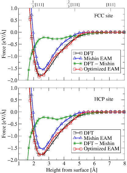
In Fig. 1 the DFT force of a Cu atom evaporating from a perfect (unrelaxed) Ag(111) surface is plotted, and is used in addition to the database. Starting from a height of [111], the force on the Cu atom is computed in steps of [111] for 13 points, then in steps of [111] until [111], where the DFT force dropped to zero. The Cu atom is directly above FCC and HCP sites to cancel forces in the plane. The difference in force between FCC and HCP is less than 0.04eV/Å for both DFT (max deviation at [111]) and EAM (max deviation at [111]). Fig. 1 shows that DFT has a stronger binding of Cu to the Ag surface than the Mishin EAM. Also plotted in Fig. 1 is the force calculated with our optimized EAM, which captures the deeper and wider well of DFT forces.
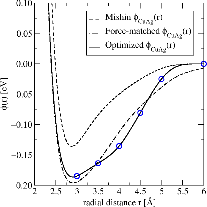
Fig. 2 shows the Cu-Ag pair potential extracted from force-matching to the DFT data. Starting from the highest point and moving towards the surface, the Cu atom feels the sum of forces from different shells of Ag atoms within a 7.2Å cut-off radius. We chose this cutoff radius because the DFT forces goes to zero at =7Å ([111]). For each , there are = 1… shells, in which there are Ag atoms at distance with directional component . The -component of the force at height is
| (1) |
where is the radial derivative of the pair potential. We build the function as a cubic spline with knot points = min{} for each . Starting from largest to smallest, Eqn. 1 is solved for using, as needed, interpolated values of for . The equations are solved successively until is self-consistent. A final self-consistency loop over all FCC and HCP forces is performed, alternating in sequence, obtaining for in the range from 2.04Å to 7.2Å. Integrating generates a quartic spline, the plotted in Fig. 2. This force-matched possess a deeper and wider energy well, capturing the stronger Cu-Ag interaction from DFT. For values smaller than 2.04Å, we linearly extrapolate .
The force-matched is refined by fitting to the monomer and dimer database. The force-matched has inaccurate energies for monomers and dimers, with the HCP site 4meV below the FCC site. Modifying does not affect monomer energies, and we find that the dimer energy difference between FF and HH changes by less than 5meV with the modifications we present later. We optimize the Cu-Ag pair potential with respect to monomer and homogeneous dimer site energy differences as the next step. We reduce the interaction range to 6Å by shifting the potential up by (5.75Å) and using quartic splines from 5Å to 6Å. The quartic splines have two equal spaced knots within the interval and matches the value, first and second derivatives at 5Å, and at 6Å goes to zero with zero slope and zero second derivative. To differentiate between FCC and HCP sites, we modify the Cu-Ag interaction in the range of the second and third nearest neighbors for a Cu atom on the surface by adding a cubic spline, with knots at 3.5Å, 4Å, 4.5Å, 5Å, and fixed end points at 3Å and 6Å. We generate (25+1)4 = 14641 possible potentials with different values at each knot point in steps of 20meV; optimization continues using narrower ranges down to 1meV. For each sweep, we select potentials with the smallest rms monomer and homogeneous dimer energy errors while also selecting for quantitatively low rms Cu height errors and potentials without multiple minimums. In Fig. 2, this optimized exhibits a wider well than the force-matched pair potential.
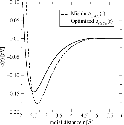
Fig. 3 shows that the optimized gives shorter and weaker bonding between Cu atoms on the Ag surface than in the Mishin EAM bulk Cu. We scale the original Mishin in 1% steps from 80% to 120%, and translate in 0.01Å steps from –0.15Å to 0.15Å; potentials with Cu lattice parameter outside of 5% of the bulk value are removed. A 82% scaling and a –0.13Å translation reproduces all relative energy differences with a final 0.5meV range optimization of the . We found during optimization that although it was possible to obtain 0.012Å rms dimer separation error or 0.5meV rms energy error, these two errors grew opposite one another. We selected for lower energy error at the expense of geometric agreement.
Thus, our optimization procedure with respect to DFT Cu monomers and dimers follows: (1) modify the to match the force of an evaporating Cu atom from Ag(111) calculated in DFT. (2) Reduce the interaction length of the force-matched and add splines to reproduce the DFT FCC/HCP site energy difference. (3) Scale and translate the to produce better energetic agreement. (4) Polish the optimized potential with the optimized . The final is plotted in Fig. 2, and in Fig. 3.
| Foiles, | ||||||||||
| Baskes, | Voter, | This | ||||||||
| ExperimentMorgenstern et al. (2004) | ab initio | DawFoiles et al. (1986) | ChenVoter (1993) | MishinMishin et al. (2001); Williams et al. (2006) | Work | |||||
| monomer energies [meV] | ||||||||||
| E(H,F) | 14 | 1 | 0 | 8 | — | 12 | ✓* | |||
| E(FH) | 96 | 68 | 39 | 62 | 93 | ✓ | ||||
| dimer energies [meV] | ||||||||||
| E(HH,FF) | 27 | 1 | 0 | 15 | — | 27 | ✓* | |||
| E(FH,FF) | 71 | 58 | — | 2 | 79 | ✓ | 71 | ✓* | ||
| E(FH,FF) | 134 | 66.5 | 57 | 61 | 137 | ✓* | ||||
| E(FH,FH) | 63 | 8.5 | 55 | ✓ | –18 | 66 | ✓ | |||
| E(FFHH) | 73 | 62 | ✓ | 6 | 69 | ✓ | 88 | — | ||
| trimer energies [meV] | ||||||||||
| E(F,F) | –16 | 41 | 9 | 33 | 9 | |||||
| E(H,F) | 17 | 38 | 9 | 50 | 42 | |||||
| E(H,F) | 42 | 2 | 1 | 23 | 45 | ✓ | ||||
| E(H,F) | 33 | –3 | 0 | 17 | 33 | ✓ | ||||
| geometries [Å] | ||||||||||
| Dimer length | baseline | 0.036 | ✓ | 0.117 | 0.054 | ✓ | 0.0796 | ✓* | ||
| rms error | ||||||||||
| Adatom height | baseline | 0.115 | 0.559 | 0.153 | 0.0397 | ✓* | ||||
| rms error | ||||||||||
In Table 1, comparison with other EAM potentials show that the optimized EAM from this work has better agreement to DFT calculations. Among the earlier potentials, the Mishin EAMMishin et al. (2001); Williams et al. (2006) comes closest to the DFT energies when compared to the Foiles-Baskes-Daw (FBD) EAMFoiles et al. (1986) and the Voter-Chen (VC) EAMVoter (1993) potentials. The FBD and VC EAM potentials did not indicate any site energy difference between FCC and HCP. None of the earlier potentials were able to capture the correct DFT energy difference between FH and FH dimers. Both FBD and Mishin EAM came within 10meV of the experimental monomer and dimer diffusion barriers, while the optimized EAM potential overestimates the experimental barriers but correctly predicts the DFT monomer diffusion barrier. The increased Cu-Ag interaction of the optimized potential were able to pull the Cu atoms closer to the Ag surface, reducing the rms height error over other potentials. While the earlier potentials do not come close to the DFT trimer energies, the optimized EAM is able to capture the correct energies for E(H,F) and E(H,F). The deviation for the trimer ground state will be discussed in Section V.
IV Results
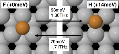
Fig. 4 shows the geometries, relative energies, and transition barriers of Cu monomers calculated with the optimized EAM. The 14meV energy difference between the FCC and HCP site also represents the difference between the transition barriers. The two transitions possible are the FH with a 93meV barrier and the 79meV barrier HF transition. The FH barrier is higher than the experimental value of 659meV,Morgenstern et al. (2004) but matches our DFT calculations for the bridging site with an energy difference of 96meV. DFT is known to overestimate surface adsorption,Stampfl (2005) and we discuss strategies to compensate in Section V. The agreement with DFT is a confirmation of our potential since the bridging site energy is not part of the optimization database.
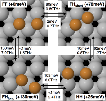
Fig. 5 shows the geometries, relative energies, and transition barriers of Cu dimers calculated with the optimized EAM. The FF dimer is the ground state and the HH dimer is 26meV higher in energy, about twice the monomer energy difference. The FH and FH dimers are two metastable configurations which are 78meV and 130meV higher in energy than FF, respectively. Dimer diffusion is more complex than that for monomers, with two intermediate states between FF and HH plus dimer rotation. With low barrier (1meV) transitions out of the FH state, the diffusion pathway through FH has a 130meV barrier for FFFHHH, and 103meV barrier for HHFHFF. The other diffusion pathway is more complicated, since an FH dimer is more likely to transition to FF (2meV barrier) than to HH (10meV barrier). This results in a 88meV barrier for FFFHHH (88meV – 2meV + 10meV), and 62meV barrier for HHFHFF. The calculated barriers are higher than the experimental barrier of 73meV,Morgenstern et al. (2004) again consistent with overestimated adsorption energies by DFT.
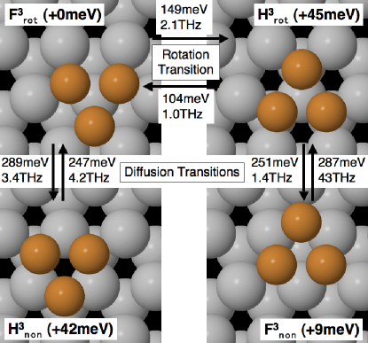
Fig. 6 shows the geometries, relative energies, and transition barriers of Cu trimers calculated with the optimized EAM. There are two different configurations for each of the FCC and HCP trimers due to the geometry of the (111) surface. The trimer triangles can either be centered around a surface Ag atom permitting rotation, F (groundstate) and H (+45meV), or not, F (+9meV) and H (+42meV). The relative energy difference between F3 and H3 trimers is approximately two to three times the monomer energy difference. The rotation transition FH has a 149meV barrier and a 104meV barrier for the reverse. The non trimers do not rotate, and transition to rot trimers on the opposite sites. These transition barriers are higher than the rotation barriers, at 290meV from FH and FH, and 250meV for the reverse. We expect, as with monomers and dimers, that the EAM overestimates the trimer transition barriers.
We construct analytical expressions for the diffusion constants of monomers, dimers, and trimers using the calculated transition barriers and attempt frequencies. The rate of jumping from a F site to a particular H site is where and are the energy barrier and the attempt frequency for the F to H transition. Then a monomer moving from one F to a new F site through an H site at temperature occurs with mean wait time of
including the three equivalent hopping sites for each monomer transition, and with a correlation factor of for monomer transitions to the original site. The Einstein diffusion relation, where is the nearest-neighbor distance between Ag atoms gives the monomer diffusion constant
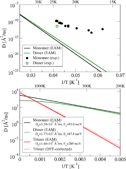
For both the dimer and trimer case, the diffusion system becomes complex and we use the continuous-time random walk formalism developed by Shlesinger and Landman.Shlesinger and Landman (1980) The diffusion constant for the dimer is computed numerically and plotted in Fig. 7, while the diffusion constant for the trimer is given by
In Fig. 7, the analytical rates from above have been plotted as diffusion coefficients against temperature along with experimental data from [Morgenstern et al., 2004] for the monomer and dimer. The experimental barriers, 659meV and 73meV for monomer and dimer are both lower than our calculated values, though no error bar is given for the dimer experimental barrier. The rate limiting barriers as T0K are calculated using data at T20K. The rate limiting barriers, 93meV, 88meV, and 289meV, correspond to the rate-limiting transition barriers identified above for the monomer, dimer, and trimer. The dimer diffusion slope decreases with increasing temperature due to the influence of both FH intermediate states. Higher temperatures samples the FH pathway; this decreases dimer diffusion as transitions through the FH state lead to rotation, i.e., FFFHHHFHFF. The prefactors for transitions out of FH are the lowest for all dimer transitions, and become rate limiting at high temperatures.
V Discussion
The Cu monomer is the basic unit for Cu islands on Ag(111), and the correct extrapolation of monomer energies and barriers to dimers and trimers indicates the optimized potential is consistent with DFT. For the monomer, the site energy difference between FCC and HCP is 14meV, twice the difference is seen between the homogeneous dimers FF and HH at 26meV, and two to three times the difference in the rot and non trimer pairs at 33meV and 45meV. The diffusion barriers for the trimer are also three times that of the monomer 289meV versus 93meV and 247meV versus 79meV. This linear relationship is explained by the fact that in the trimer diffusional transitions, all three atoms move simultaneously over each of their respective bridging sites, thus the trimer as a whole experiences a barrier three times as large. In the dimer system, diffusion moves one atom at a time and the barrier is comparable to that of the monomer.
EAM produces higher diffusion barriers for monomer and dimer than in experiment,Morgenstern et al. (2004) but gives diffusion barriers that match DFT. This effect is consistent with the observed overestimation of surface adsorption energy by DFT calculations.Stampfl (2005) Compared to experiments for monomer and dimer, the barriers are overestimated by approximately 10 to 15meV. Since diffusion for both the monomer and dimer proceeds one Cu atom at a time, we expect the bridging site between F and H to be overestimated by 15meV. For general diffusion barriers, a 15meV reduction should be applied for each concurrent Cu atom in the transition when comparing to experiment. For example, a three-fold reduction of 45meV will need to be applied to the trimer diffusion barriers.
Trimers were not included in our optimization database and calculations in DFT and the optimized EAM differ when looking at the energetics between rot and non trimers. DFT calculates that the two non trimers are 25meV lower in energy than predicted by our optimized EAM, making the ground state trimer configuration F rather than F. We expect the deviation to be mainly caused by the center Ag atom under the rot trimer, whose embedded “electron density” is 16% higher than an Ag atom in the bulk. This density is beyond the range present in the monomer and dimer database. Modifying the embedding function, as done in surface embedded-atom method (SEAM)Haftel (1993); Haftel and Rosen (1995) may offset this effect by penalizing densities away from the bulk value. Although the relative energy between rot and non trimers are not correct, the optimized EAM correctly predicts the energy difference between F and H, and F and H. Adding a Cu atom to a rot trimer will create a non trimer subsection, and in larger islands, this pairing of rot and non trimers allows the correct energy differences to be calculated. We expect the trimer diffusion barrier to remain three times that of the monomer even with the change in ground state. A new estimate of trimer diffusion can be computed by splitting the 25meV energy difference between forward and reverse diffusion barriers, e.g. lower the rot to non barrier by 12.5meV and raising the non to rot by 12.5meV. This change does not affect the transition paths and therefore does not change the overall diffusional dynamics of the trimer system, increasing the rate limiting barrier to 292meV from 289meV (c.f. Fig. 7). Applying the 45meV over-adsorption correction gives a barrier of 247meV for trimer diffusion to compare with experiment.
VI Conclusion
We present a method to optimize an EAM potential for heterogeneous surface system using ab initio data. The optimized EAM potential reproduces DFT energies for Cu monomers, dimers, and trimers on Ag(111). Diffusion barriers for monomers, dimers, and trimers are calculated to be 93meV, 88meV, and 289meV, which match available DFT data, but exceed experimental values. To correct for the overestimated barriers, a 15meV reduction is applied for each concurrently transitioning Cu atom. We found a 25meV energy discrepancy between rot and non trimers when compared with DFT. This discrepancy is not worse for larger islands due to correct energy difference between F-trimers and H-trimers calculated by the potential compared with DFT. We expect the new EAM potential to accurately describe the diffusion and energetics of larger Cu islands on Ag(111).
Acknowledgements.
The authors thank John Weaver and Andrew Signor for helpful discussions. This research was supported by NSF/DMR grant 0703995, and 3M’s Untenured Faculty Research Award.References
- Wen et al. (1994) J.-M. Wen, S.-L. Chang, J. W. Burnett, J. W. Evans, and P. A. Thiel, Phys. Rev. Lett. 73, 2591 (1994).
- Kellogg and Voter (1991) G. L. Kellogg and A. F. Voter, Phys. Rev. Lett. 67, 622 (1991).
- Bartelt et al. (1999) M. C. Bartelt, C. R. Stoldt, C. J. Jenks, P. A. Thiel, and J. W. Evans, Phys. Rev. B 59, 3125 (1999).
- Antczak and Ehrlich (2007) G. Antczak and G. Ehrlich, Surface Science Reports 62, 39 (2007).
- Papanicolaou et al. (1998) N. I. Papanicolaou, G. A. Evangelakis, and G. C. Kallinteris, Computational Materials Science 10, 105 (1998).
- Montalenti and Ferrando (1999) F. Montalenti and R. Ferrando, Phys. Rev. B 59, 5881 (1999).
- Bogicevic (1999) A. Bogicevic, Phys. Rev. Lett. 82, 5301 (1999).
- Lorensen et al. (1999) H. T. Lorensen, J. K. Nørskov, and K. W. Jacobsen, Phys. Rev. B 60, R5149 (1999).
- Chirita et al. (1999) V. Chirita, E. Munger, J. Greene, and J.-E. Sundgren, Surface Science Letters 436, L641 (1999).
- Papathanakos and Evangelakis (2002) V. Papathanakos and G. A. Evangelakis, Surface Science 499, 229 (2002).
- Brune et al. (1999) H. Brune, G. S. Bales, J. Jacobsen, C. Boragno, and K. Kern, Phys. Rev. B 60, 5991 (1999).
- Morgenstern et al. (2004) K. Morgenstern, K.-F. Braun, and K.-H. Rieder, Phys. Rev. Lett. 93, 056102 (2004).
- Ozoliņš et al. (1998) V. Ozoliņš, C. Wolverton, and A. Zunger, Phys. Rev. B 57, 4816 (1998).
- Hamilton (1996) J. C. Hamilton, Phys. Rev. Lett. 77, 885 (1996).
- Foiles et al. (1986) S. M. Foiles, M. I. Baskes, and M. S. Daw, Phys. Rev. B 33, 7983 (1986).
- Kresse and Hafner (1993) G. Kresse and J. Hafner, Phys. Rev. B 47, RC558 (1993).
- Kresse and Furthmüller (1996) G. Kresse and J. Furthmüller, Phys. Rev. B 54, 11169 (1996).
- Vanderbilt (1990) D. Vanderbilt, Phys. Rev. B 41, 7892 (1990).
- Kresse and Hafner (1994) G. Kresse and J. Hafner, J. Phys.: Cond. Mat. 6, 8245 (1994).
- Perdew and Zunger (1981) J. P. Perdew and A. Zunger, Phys. Rev. B 23, 5048 (1981).
- Plimpton (1995) S. J. Plimpton, J. Comp. Phys. 117, 1 (1995), URL http://lammps.sandia.gov/index.html.
- Mills and Jónsson (1994) G. Mills and H. Jónsson, Phys. Rev. Lett. 72, 1124 (1994).
- Henkelman and Jónsson (1999) G. Henkelman and H. Jónsson, J. Chem. Phys. 111, 7010 (1999).
- Vineyard (1957) G. H. Vineyard, Journal of Physics and Chemistry of Solids 3, 121 (1957).
- Mishin et al. (2001) Y. Mishin, M. J. Mehl, D. A. Papaconstantopoulos, A. F. Voter, and J. D. Kress, Phys. Rev. B 63, 224106 (2001).
- Williams et al. (2006) P. L. Williams, Y. Mishin, and J. C. Hamilton, Modelling Simul. Mater. Sci. Eng. 14, 817 (2006).
- Voter (1993) A. F. Voter, Tech. Rep., Los Alamos Unclassified Technical Report (1993).
- Stampfl (2005) C. Stampfl, Catalysis Today 105, 17 (2005).
- Shlesinger and Landman (1980) M. F. Shlesinger and U. Landman, Applied Stochastic Processes (Academic Press, New York, 1980).
- Haftel (1993) M. I. Haftel, Phys. Rev. B 48, 2611 (1993).
- Haftel and Rosen (1995) M. I. Haftel and M. Rosen, Phys. Rev. B 51, 4426 (1995).
- Yuan et al. (2003) X. Yuan, K. Takahashi, Y. Ouyang, and T. Onzawa, J. Phys.: Condens. Matter 15, 8917 (2003).