Effects of Quantum Tunneling in Metal Nano-gap on Surface-Enhanced Raman Scattering
Abstract
The quantum tunneling effects between two silver plates are studied using the time dependent density functional theory. Our results show that the tunneling depends mainly on the separation and the initial local field of the interstice between plates. The smaller separation and larger local field, the easier the electrons tunnels through the interstice. Our numerical calculation shows that when the separation is smaller than 0.6 nm the quantum tunneling dramatically reduces the enhancing ability of interstice between nanoparticles.
pacs:
33.20.Fb, 03.65.Xp, 78.67.BfMetal nano-gaps offering strong surface plasmon couplings have very rich physical properties. The related studies have been very hot topics in the field of plamonics, e.g., single molecule surface-enhanced Raman spectroscopy Xu1 (1999); Mich (2000), optical nano-antennas Muhlschlegel2005 (2005), high-harmonic generation Kim2008 (2008). The electromagnetic (EM) enhancement near the metal surface, which is caused by the resonant excitation of surface plasmon Raether , is the dominating reason for the surface-enhanced Raman scattering (SERS) Mosk ; Xu1 (1999). Huge SERS with single molecule sensitivity can be obtained when molecules are located in the nano-gap between two metallic nano-structures Xu1 (1999); Mich (2000); Xu2000 (2000); Talley (2005); HWei (2008). A lot of efforts have been made to seek extreme sensitive SERS substrates Haes1 (2004); Haes2 (2004); KZhao (2006).
Theoretically, people have used many methods based on the classical electrodynamics Xu2007 (2007); Flatau (1993); Futamata (2003) to estimate the SERS enhancement. These classical results indicate that the smaller the nano-gap, the higher the enhancement. However, as the separation decreases to 1 nm, the displacive current would partly become electron tunneling current which can reduce the EM enhancement substantially Otto (2002). A recent experiment on the four-wave mixing at coupled gold nanoparticles clearly demonstrated that the quantum tunneling (QT) effect becomes significant for the distance smaller than 0.2 nm Danck (2007), and a recent study of the plasmon resonance of a nanoparticle dimer gave quantum description of such a phenomenonNordlander (2009). It is well known that the EM enhancement is the main contribution to SERS. Its enhancement factor is proportional to the fourth power of the local field enhancement, i.e. , where = with and being the local enhanced electric field and the incident electric field, respectively. Therefore, even for small QT effects on , after a fourth power, the influence to SERS could be huge. In this Letter we investigate the effects of QT on SERS with the time dependent density functional theory RG (1984). Our studies are able to quantify these effects and point out at exactly what conditions the QT has to be taken into account.
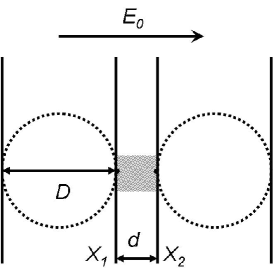
As the “hot spot”, where the SERS is strongest, is localized in a very small volume in the interstice between particles, it is convenient to investigate the QT effect between two closely placed plates instead of two nano-particles. As shown in Fig. 1, in the vicinity of the “hot spot” (shaded area), two plates are not much different from two nano-spheres. Besides we use two approximations for our numerical calculations: (1) In the generalized Mie theory, the electric current inside nano-sphere is set to be zero Xu2007 (2007), so we can regard the silver plates as equipotential bodies at all time in our calculation; (2) The laser field is treated as a static electric field, and the QT effect in an oscillating field can be described by the results of static field in one period of laser. With these simplifications, when the separation is not very small, the electric tunneling effect can be studied by the method developed by Simmons simmons (1963), which regards electrons are tunneling through a voltage barrier. We find that Simmons’ method is not proper when the distance nm. For example, at nm, the mean barrier height becomes negative at low voltage limit, indicating the failure of this method.
In this work we adopt a more sophisticated method, the time dependent density functional theory (TDDFT) RG (1984) with the jellium model, where the ionic lattice is treated as a uniform positive charge background. In this method, we solve self-consistently a set of time dependent Schrödinger equations,
| (1) |
where we have used the atomic units and denotes a quantum state inside the Fermi surface of the silver plate. is the external potential coming from the laser field and its induced field. is the effective potential felt by an electron through Coulomb interaction and correlation and exchange; it depends on the electron density. In our approach, we use Crank-Nicholson method cranknicholson to update the wave function. To quantify the QT effects on the SERS, we monitor time evolution of the potential difference between the two silver plates. We compute with the formula
| (2) |
where and are coordinates of the left and right surfaces of the right (left) plate.
Let us now turn on the laser field. The electrons inside each silver plate will start moving instantly to counter-balance the applied electric field so that the total electric field inside each plate is zero. At the same time, an enhanced field is induced in the “hot spot”. Afterwards, the electrons will start to tunnel between the two silver plates under the following external potential
| (3) |
It is clear from the above analysis that the initial electron state for the Schrödinger equations in Eq.(1) is the state where the electrons have moved to counter-balance the incident laser field. To obtain this initial state, we compute with the method developed by Schulte FK (1976) the ground state of the metallic plate under the following external potential
| (4) |
where , are the left and right surfaces of the plate.
Figure 2 shows the calculated time evolution of the potential difference between the two plates separated by nm. The strength of the incident electric field is V/m, corresponding to a laser with power and focal spot m. In most SERS experiments, even for single molecule detection, a much smaller W is used Xu1 (1999); Mich (2000). The diameter of nano-particle is nm. Note that we have calculated for three different diameters nm and the results are almost identical . This indicates that the physical process in the “hot spot” is not sensitive to geometric features that are far away, further justifying our replacement of the spheres with the plates.
We see in Fig. 2 that decays while oscillating with a frequency close to the bulk plasma frequency. The decay gets severe as the separation becomes smaller. This kind of decay can be intuitively understood by viewing the system as a bad capacitor that leaks current.


To measure the decay, or the QT suppression of the enhanced field, we introduce a decay rate defined by
| (5) |
where is the typical optical period of the incident laser, e.g., fs for a laser wavelength nm. Note that is not the value of but the averaged value of over one oscillation period at . As the distance decreases, the potential difference decays with time dramatically. At nm, the local field is reduced by after half optical period ( nm), that is, the SERS enhancement is times () smaller than the one obtained from classical theory. By contrast, at nm, the reduction of the local field enhancement by the QT is only 14%, corresponding to one time decrease of SERS enhancement factor. This means that the enhancement can be sustained if the separation is larger than 1 nm. The decay rates for these different separations are computed and plotted in Fig.3, where we see decreases exponentially as increases. Specifically, when the separation is smaller than 0.6 nm, the QT can reduce the local field significantly.
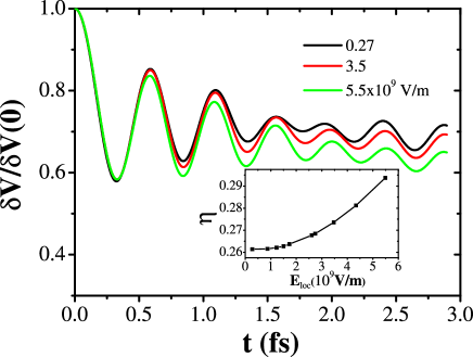
It is evident that both the enhancement factor and the laser power can affect the QT via the enhanced local field , which is proportional to . We find through numerical calculations that for the range of laser power commonly used in experiment, the deciding factor is , not individual values of and . For example, we find that the time evolution of for mW, and W, is almost the same (not shown). This means that we need to consider only the enhanced local field . Figure 4 shows the time evolutions of for different at nm and nm. We see clearly that larger local field induce larger QT, which in turn reduces the enhancement. As shown in the inset in Fig. 4, the decay rate decreases slowly when V/m, and reaches a non-zero constant when goes to 0. This can be explained by the fact that when the tunneling is small, we still have the linear current-voltage relation simmons (1963), . From this relation, we obtain
| (6) |
Therefore, when , we have the minimal decay rate . It should be noted that the minimum decay rate is determined by the separation. At nm, the minimum reduction is about .
We emphasize that the reduced SERS calculated by us is not necessarily the overall SERS of a molecule placed in the nano-gap. With a molecule in the gap, the situation can become much more complex. On the one hand, the oscillatory tunneling current can be coupled to the molecule inelastically, generating additional Raman signals Ho ; Johansson . On the other hand, the chemical enhancement can also be affected by the QT zhao . Thus the reduced EM enhancement might be compensated or even over- compensated by these two factors. More studies are needed to clarify the issue.
In sum, we have investigated the time evolution of QT between two plates using the TDDFT method. We have found that smaller separation and larger local field result in stronger QT. Our numrical results show that when the separation is smaller than nm, the suppression of the EM part of enhancement in SERS is very significant for the common laser power used in experiment.
This work was supported by NSF of China (10625418, 10825417), by MOST (2005CB724500, 2006CB921400, 2006DFB02020, 2007CB936800, 2009CB930704), and by the “Bairen” projects of CAS.
References
- Xu1 (1999) H. X. Xu, E. J. Bjerneld, M. Käll, L. Börjesson, Phys. Rev. Lett. 83, 4357 (1999).
- Mich (2000) A. M. Michaels, J. Jiang, L. Brus, J. Phys. Chem. B 104, 11965 (2000).
- Muhlschlegel2005 (2005) P. Mühlschlegel, H. J. Eisler, O. J. F. Martin, B. Hecht, D. W. Pohl, Science 308, 1607 (2005).
- Kim2008 (2008) S. Kim, J. Jin, Y. J. Kim, I. Y. Park, Y. Kim, S. W. Kim, Nature 453, 757 (2008).
- (5) H. H. Raether, Surface Plasmons (Springer, Berlin, 1988).
- (6) M. Moskovits, in Top. Appl. Phys. (Springer-Verlag Berlin, Berlin, 2006), pp. 1.
- Xu2000 (2000) H. X. Xu, J. Aizpurua, M. Käll, P. Apell, Phys. Rev. E 62, 4318 (2000).
- Talley (2005) C. E. Talley, J. B. Jackson, C. Oubre, N. K. Grady, C. W. Hollars, S. M. Lane, T. R. Huser, P. Nordlander, N. J. Halas, Nano Lett. 5, 1569 (2005).
- HWei (2008) H. Wei, F. Hao, Y. Z. Huang, W. Z. Wang, P. Nordlander, H. X. Xu, Nano Lett. 8, 2497 (2008).
- Haes1 (2004) A. J. Haes, S. L. Zou, G. C. Schatz, R. P. Van Duyne, J. Phys. Chem. B 108, 109 (2004).
- Haes2 (2004) A. J. Haes, S. L. Zou, G. C. Schatz, R. P. Van Duyne, J. Phys. Chem. B 108, 6961 (2004).
- KZhao (2006) K. Zhao, H. X. Xu, B. H. Gu, Z. Y. Zhang, J. Chem. Phys. 125, 081102 (2006).
- Xu2007 (2007) Z. P. Li, H. X. Xu, J. Quant. Spectrosc. Radiat. Transfer 103, 394 (2007).
- Flatau (1993) P. J. Flatau, K. A. Fuller, D. W. Mackowski, Appl. Opt. 32, 3302 (1993).
- Futamata (2003) M. Futamata, Y. Maruyama, M. Ishikawa, J. Phys. Chem. B 107, 7607 (2003).
- Otto (2002) A. Otto, J. Raman Spectrosc. 33, 593 (2002).
- Danck (2007) M. Danckwerts, L. Novotny, Phys. Rev. Lett. 98, 4 (2007).
- Nordlander (2009) J. Zuloaga, E. Prodan, P. Nordlander, Nano. Lett. 9, 887 (2009).
- RG (1984) E. Runge, E. K. U. Gross, Phys. Rev. Lett. 52, 997 (1984).
- simmons (1963) J. G. Simmons, J. Appl. Phys. 34, 2581 (1963).
- (21) R. S. Varga, Matrix Iterative Analysis (Prentice-Hall, Englewood Cliffs, NJ, 1962), p. 263.
- FK (1976) F. K. Schulte, Surf. Sci. 55, 427 (1976).
- (23) B. C. Stipe, M. A. Rezaei, W. Ho, Science 280, 1732 (1998).
- (24) P. Johansson, Phys. Rev. B 58, 10823 (1998).
- (25) K. Zhao, M. C. Troparevsky, Di Xiao, A. G. Eguiluz, and Zhenyu Zhang, preprint (accepted by PRL)