Symmetry and the generation and measurement of optical torque
Abstract
A key element in the generation of optical torque in optical traps, which occurs when electromagnetic angular momentum is transferred from the trapping beam to the trapped particle by scattering, is the symmetries of the scattering particle and the trapping beam. We discuss the effect of such symmetries on the generation and measurement of optical torque in optical tweezers, and some consequent general principles for the design of optically-driven micromachines.
keywords:
Optical tweezers , laser trapping , symmetry , optical torque foo1 Introduction
Optical trapping, exemplified by the single-beam gradient trap, or optical tweezers (Ashkin et al., 1986), has developed from an interesting novelty into a widely-used and powerful tool with many applications in biophysics and other areas (Ashkin, 2000; Moffitt et al., 2008). Uses include the measurement of forces on the order of piconewtons, such as the adhesion forces on a cellular level (Knöner et al., 2006) and forces in single-molecule studies (Williams and Rouzina, 2002), as well as manipulation of microscopic objects, including live bacteria and eukaryote cells.
An optical tweezers trap is conceptually simple: a high numerical aperture lens, typically a microscope objective lens, is used to focus a laser beam to a diffraction-limited spot. The sample, consisting of the microscopic objects one intends to trap or manipulate (often polystyrene or silica microspheres) suspended in a fluid, which would usually be water or a biological buffer solution, is placed on a stage, and the objects, as long as their refractive index is higher than that of the suspending fluid, and they are not too reflective or absorbing (Stilgoe et al., 2008), can be trapped in the bright focal spot.
The optical forces responsible for trapping are fundamentally the result of the transfer of momentum from the beam through scattering of the trapping beam (Ashkin et al., 1986; Ashkin, 1992; Nieminen et al., 2007a); this possible due to the transport of momentum by electromagnetic fields, with the optical force being equal to the rate of transfer of momentum from the beam to the particle.
Since angular momentum can also be carried by electromagnetic fields, including light, the possibility of exerting optical torque on particles, trapped or otherwise, is evident. This introduces the possibility of six-degrees-of-freedom, with the orientation of a trapped particle being controlled, in addition to its position—this would be a major advance in the manipulation possible with optical tweezers. Rotation can also be used as a tool to actively probe the physical properties of the surrounding medium (Nieminen et al., 2001; Bishop et al., 2004; La Porta and Wang, 2004). In addition, it could allow the development of practical optically-driven micromachines (Friese et al., 2001; Galajda and Ormos, 2001; Nieminen et al., 2006a). A significant amount of progress has been achieved in all of these areas (e.g., Bayoudh et al., 2003; Parkin et al., 2007; Kelemen et al., 2006), using a diverse range of methods to generate the optical torque.
A key element determining whether or not the transfer of electromagnetic angular momentum to a particle by scattering is possible is the symmetries of the scattering particle and the trapping beam (Konz and Benford, 2003; Nieminen, 2004; Benford and Konz, 2004; Nieminen et al., 2004). Therefore, consideration of the effects of symmetry can provide insight into rotational optical micromanipulation and design of optically-driven micromachines and a unified overview of the generation of optical torque.
2 Optical angular momentum
Optical forces have a long and interesting history (Worrall, 1982), starting with Kepler’s conjecture that radiation pressure was responsible to the direction of comet tails (Kepler, 1619). However, due to their smallness, practical applications in the laboratory did not appear feasible until Ashkin noted that only very small forces are needed to manipulate very small objects (Ashkin, 2000), which, notably, led to the invention of optical tweezers (Ashkin et al., 1986). The fundamental principle by which optical tweezers operate is the exchange of momentum between the trap beam and a particle within the trap (Ashkin et al., 1986; Nieminen et al., 2007b).
It was suggested as early as 1909 by Poynting (1909) that light can carry angular momentum as linear momentum. While Poynting was skeptical as to whether such torques could be measured, this was achieved in 1936 by Holbourn (1936) and Beth (1936).
Most of the earliest optical tweezers-based demonstrations of optical torque made use of absorption, combined with laser beams carrying angular momentum (He et al., 1995; Friese et al., 1996; Simpson et al., 1997), which has very limited practical use due to the resulting heating, which, for example, could lead to rapid death of live specimens, and in any case, makes three-dimensional trapping more difficult or even impossible.
More promising was the use of birefringent materials (Friese et al., 1998; Bishop et al., 2004; La Porta and Wang, 2004), or specially-shaped objects (Higurashi et al., 1994, 1997; Bonin et al., 2002; Cheng et al., 2002; Bishop et al., 2003; Neale et al., 2005) which can themselves be made of birefringent materials, or be shape-birefringent (Born and Wolf, 1997).
Notably, these types of methods, using birefringence (due to either the material or shape) which affects the polarization of the trapping beam and therefore depends on the spin angular momentum of light, and the use of shapes which depend on, and affect, the spatial structure of the trapping beam, and therefore make use of the orbital angular momentum of light, are often viewed as distinct physical mechanisms.
It is true that there are important differences between spin and orbital angular momenta, but few of them will be of importance here. One difference that will turn out to be important is that spin angular momentum can be readily determined by measurement of the Stokes parameters (Crichton and Marston, 2000). However, it is still worth reviewing the basic elements of electromagnetic angular momentum, especially since there is ongoing debate within the literature concerning the angular momentum of circularly polarized waves (Humblet, 1943; Stewart, 2005; Pfeifer et al., 2006).
The controversy arises since there are two paths we can take to determining the angular momentum density or flux. Firstly, we can assume that the angular momentum density is the moment of the momentum density, , where is the position vector relative to the origin of our chosen coordinate system, and and are the electric and magnetic fields respectively, which leads to the curious result that a circularly polarized plane wave carries zero angular momentum in the direction of propagation, in contradiction to the usual quantum mechanical result of angular momentum per photon. This choice of angular momentum density implicitly states that there is no spin angular momentum—the spin angular momentum is the part of the total angular momentum which is independ of the choice of origin about which moments are taken; taking in the above expression for the angular momentum density yields a spin of zero.
Secondly, we can begin with the Lagrangian for the electromagnetic radiation field, and, via Noether’s (1918) theorem, obtain the canonical stress tensor and an angular momentum tensor. The angular momentum tensor can be divided into spin and orbital components (Jauch and Rohrlich, 1976; Soper, 1976), based on the independence of the spin from the choice of origin. For a circularly polarized wave, the spin would be , where is the irradiance and the angular frequency, in disagreement with the first result, and in agreement with the quantum mechanical result. This separation of the angular momentum density into spin and orbital parts is, in general, not gauge-invariant, and it is common to transform the canonical stress tensor into a summetric stress tensor, with a gauge-invariant result for the angular momentum density, yielding the integral of . Jauch and Rohrlich (1976) carefully point out that this transformation requires the dropping of surface terms at infinity. The reverse of this procedure, obtaining the spin and orbital terms starting from , involving the same surface terms, had already been shown by Humblet (1943). For and physically realisable beam, these surface terms vanish, and despite the controversy, both expressions for the angular momentum density yield the same total angular momentum and torque exerted on an object (Zambrini and Barnett, 2005; Nieminen et al., 2007c).
Since we are interested in torque within optical tweezers, where we have a monochromatic wave, the gauge-invariance of the separation of the angular momentum into spin and orbital parts is also a non-issue, since in this case, the separation is gauge-invariant (Crichton and Marston, 2000; Barnett, 2002).
Consequently, the spin angular momentum flux of a paraxial electromagnetic beam, where the wavefronts are almost plane (by definition), varies from per photon in the direction of propagation for right circular polarization, through zero for linear polarization, to per photon for left circular polarization. In classical terms, these extremes are , where is the beam power. Linear or elliptical polarization can be represented by the superposition of two circularly polarized components of opposite handedness; the total spin angular momentum is equal to the sum of the momentum of the two components, which, if they are of equal power, will be zero.
Since, in the paraxial limit, the spatial structure of the beam is independent of the polarization (since it is described by a solution of the scalar paraxial wave equation), the spin and orbital angular momenta are independent of each other (Allen et al., 1992, 1999). Thus, an excellent formalism for the description of the angular momentum of paraxial beams is provided by the combination of Laguerre–Gauss beam modes and circularly polarized components (Heckenberg et al., 1999; Allen et al., 1999; Nienhuis, 2008). Each Laguerre–Gauss mode is described by a radial mode index and an azimuthal mode index , and is denoted LGpℓ. Each mode has an azimuthal phase dependence of , where is the azimuthal angle. This azimuthal dependence is typical of that in solutions to PDEs in rotational coordinate systems obtained by separation of variables. Each mode also has a well-defined orbital angular momentum flux of per photon about the beam axis, or , which is also typical of such solutions. In this case, the modes are orthogonal w.r.t. orbital angular momentum, and the total orbital angular momentum about the beam axis, , can be found by adding the individual angular momenta of each mode:
| (1) |
where are the mode amplitudes, and units are chosen such that the total power is equal to
| (2) |
The total angular momentum flux about the beam axis, , is then the sum of the orbital () and spin () components,
| (3) |
where
| (4) |
where is the degree of circular polarization, which varies from for right circular polarization to for left circular.
However, for a tightly focussed beam such as employed in optical tweezers, the paraxial approximation cannot be used—it is necessary to use modes which are solutions of the vector Helmholtz equation. It is convenient to begin with a set of solutions to the scalar Helmholtz equation, , from which a set of solutions to the vector Helmholtz equation can be obtained:
| (5) | |||||
| (6) | |||||
| (7) |
where is a unit vector or a constant vector (Brock, 2001). The wavefunctions are curl-free, while the and wavefunctions are divergence-free. Therefore, for electromagnetic fields, we only require and . We can also note that .
In spherical coordinates, we can readily write a general solution to the scalar Helmholtz equation:
| (8) |
where are the mode amplitudes, are spherical Bessel functions, and are normalised spherical harmonics. The resulting vector solutions are the regular vector multipole fields, or vector spherical wavefunctions (VSWFs):
| (9) | |||||
where are normalization constants, and , , and are the vector spherical harmonics (Mishchenko et al., 2000; Waterman, 1971; Mishchenko, 1991; Jackson, 1999).
Since the spherical harmonics have an azimuthal dependence of , we once again obtain angular momentum about the beam axis in terms of the azimuthal mode index (); in this case we have the total angular momentum about the beam axis equal to per photon, or , rather than just the orbital angular momentum. The radial mode index also relates to the angular momentum—the VSWFs are eigenfunctions of the angular momentum operator , with eigenvalues , as well as the angular momentum operator , with eigenvalues . As a consequence of this, it is clear that we must have . The radial behaviour of each VSWF mode depends on spherical Bessel functions , which are peaked in the vicinity of . Therefore, the minimum width of a focussed beam depends on its angular momentum flux (Nieminen et al., 2008a); this has been noted both experimentally (Curtis and Grier, 2003) and on elementary theoretical grounds Courtial and Padgett (2000). An interesting result of this, since the minimum width of a beam also depends on its wavelength, which also affects the angular momentum flux due to the dependence of angular momentum on the frequency (or in quantum terms, the angular momentum per photon is constant, and the photon flux increases as the frequency is decreased), this minimum width is independent of the wavelength and whether the angular momentum is spin, orbital, or a combination of the two.
Since spherical harmonics are a common feature of solutions to PDEs obtained by separation of variables in spherical coordinate systems, they, and their relationship to angular momentum, are discussed in many sources, most commonly in the context of quantum mechanics (e.g., Rose, 1957; Varshalovich et al., 1988).
3 Symmetry, scattering, and angular momentum
Since we are already considering the trapping beam as a superposition of VSWFs, it is natural to use the T-matrix formalism (Nieminen et al., 2003a; Kahnert, 2003; Mishchenko et al., 2000; Waterman, 1971; Mishchenko, 1991; Jackson, 1999). For this, we need to be able to describe the scattered wave, for which we use the outgoing VSWFs instead of the regular VSWFs; to obtain these, we simply replace the spherical Bessel functions in the regular VSWFs with spherical Hankel functions of the first kind (assuming a time-dependence of —if we have chosen a time dependence of , we use spherical Hankel functions of the second kind ).
Since “T-matrix method” is often used synonymously with ”extended boundary condition method” (EBCM) which, properly speaking, is a method of calculating the T-matrix (Nieminen et al., 2003a; Kahnert, 2003), it is worth briefly describing the T-matrix description of scattering. Essentially, we expand both the incident and scattered waves in terms of a sufficiently complete basis set of functions ( for the incident wave, and for the scatterered wave, where is a mode index labelling the discrete modes), each of which is a solution of the Helmholtz equation:
| (10) |
| (11) |
where are the expansion coefficients for the incident wave, and are the expansion coefficients for the scattered wave. If the response of the scatterer is linear, the relationship between the incident and scattered waves can be written as a linear system
| (12) |
or, in more concise notation, as the matrix equation
| (13) |
where are the elements of the T-matrix.
Note that apart from the assumptions that the scattering is elastic and monochromatic, there are no other restrictions other than that a suitable basis set exists. This formalism can be used for a wide range geometries, including compact particles (ideally treated in spherical coordinates), generalised cylindrical particles and surfaces, and different types of waves, including scalar and vector waves.
Since we are interested in the transfer of angular momentum to the scatterer, it is convenient to make use a basis of incoming and outgoing VSWFs, rather than regular and outgoing. The incoming VSWFs are simply obtained by replacing the spherical Bessel functions in the regular VSWFs with spherical Hankel functions of the second kind .
Thus, while we began with the incident field written as
| (14) |
we can replace this with the purely incoming part of the incident field,
| (15) |
In both cases, the scattered field is written
| (16) |
but it is important to note that the “scattered” field is not the same in the two cases—in the first case, it is the scattered field in the usual usage of the term, while in the second, it is the total outgoing portion of the field, which includes the outgoing part of the incident field. Since , and , and the purely outgoing mode coefficients for the second case () are related to the scattered field amplitudes in the first case () by and . The T-matrix itself will also differ in the two cases—using the regular expansion, the T-matrix in the absence of a scatterer is a zero matrix, while using the incoming field expansion, the no-scatterer T-matrix is the identity matrix. The relationship between them is ; the T-matrix for the second case is typically written as and called the S-matrix.
The angular momentum flux into or out of the system can be found by integrating the moment of the momentum flux density
| (17) |
over a sphere surrounding the scatterer. Taking care to find the moment first, and then taking the far-field limit, this integral can be performed analytically if the fields are written in terms of VSWFs, for normalised angular momentum about the -axis of
| (18) |
where
| (19) |
is the incident power. This is the optical torque exerted on the scatterer, in units of per photon. The spin and orbital contributions to the torque can be calculated if desired (Crichton and Marston, 2000; Bishop et al., 2003); the spin torque is
| (20) | |||||
The remainder of the torque is the orbital contribution.
In optical tweezers, the incident beam that is focussed by the objective to produce the trapping beam typically has uniform orbital angular momentum. In conventional optical trapping, this is a Gaussian beam, with zero orbital angular momentum, while if one is intending to rotate trapped particles, this could be a Laguerre–Gauss beam carrying non-zero orbital angular momentum. In either case, the beam can also carry spin angular momentum due to circular polarization. The angular momentum flux of this incident beam is determined by the Laguerre–Gauss azimuthal mode , and the degree of circular polarization . The polarization state will, in general, be the result of superposition of left- and right-circular modes with . After focussing, however, the angular momentum is described by the VSWF azimuthal mode . The total angular momentum is unchanged by being focussed (Nieminen et al., 2008b), so
-
1.
only VSWF modes can be nonzero,
-
2.
for circular polarisation, either the modes or the modes will be nonzero, but not both,
-
3.
and both will be nonzero for plane or elliptical polarisation.
Thus, we will typically have two sets of modes, separated by an angular momentum difference of .
While finding the VSWF expansion from the original Laguerre–Gauss expansion presents both theoretical and practical difficulties, primarily as a result of the VSWF being solutions to the vector Helmholtz equation, while the Laguerre–Gauss modes are solutions to the scalar paraxial wave equation, there are a number of ways in which it can be done (Nieminen et al., 2003b, 2007c).
What then of the effect of the symmetry of the scattering particle? With respect to the azimuthal coordinate , every object is periodic, even if completely devoid of symmetry (in which case, the period is , since the object must be rotated by a complete rotation before matching its original appearance). Thus, the azimuthal dependence of the fields and the boundary conditions (i.e., the effect of the scatterer) present an exact mathematical analogy with the case of a planar grating illuminated by a plane wave. For the grating, if the component of the wavevector of the incident wave along the grating is , and the component of the reciprocal lattice vector of the grating along the grating is , the scattered waves have a discrete angular spectrum with wavevectors given by , where is the order of scattering. This is a fundamental result of Floquet’s theorem. In the case of the azimuthal behaviour of the fields, the azimuthal mode index plays the part of the component of the wavevector, and the order of discrete rotational symmetry (a scatterer has -th order discrete rotational symmetry if it is indistinguishable times during a complete rotation) is equivalent to the lattice vector. Thus, a discrete azimuthal spectrum, with azimuthal mode indices
| (21) |
is obtained, where is the azimuthal mode index of the incident wave. Since determines the angular momentum of each mode, we see that the optical torque is strongly influenced by the symmetry of the scatterer.
For scatterers that are mirror-symmetric, upward and downward coupling must be equal, in the sense that, for example, a mirror-symmetric scatterer of 2nd order rotational symmetry (such as a long rod), T-matrix elements coupling from modes to modes will have the same magnitudes as the elements coupling from to modes. For chiral scatterers, these T-matrix elements will, in general, be different.
Two cases can be simply dealt with. Firstly, if the particle is devoid of symmetry (i.e., ), the incident wave is coupled to all possible scattered modes, and little can be said about the details of possible effects. Secondly, if the particle is axisymmetric (), we only have , and the angular momentum per photon is unchanged. Thus, an axisymmetric particle can only experience an optical or electromagnetic torque if the photon flux changes due to absorption (or, in principle, gain). This lack of coupling between different angular momenta is widely exploited in the calculation of the T-matrix (Nieminen et al., 2003a; Mishchenko et al., 2000; Waterman, 1971; Mishchenko, 1991), in additions to the benefit of axisymmetry turning 2D surface integrals into 1D line integrals, or 3D volume problems into 2D surface problems (Loke et al., 2007). Even in the case of discrete rotational symmetry rather than axisymmetry, the restricted coupling between modes (21) can still be used to reduce computational time by orders of magnitude (Kahnert, 2005; Nieminen et al., 2006b, 2007c).
We can also note some rotation properties of T-matrices. Since the individual VSWF modes have an azimuthal dependence of , a rotation of the coordinate system of about the -axis must induce a phase change of in the VSWF modal amplitudes. The combination of rotation of the incident and scattered fields is equivalent to a phase change of for the T-matrix element coupling modes of azimuthal index and . If the scatterer is rotating, then , and the scattered light experiences a rotational Doppler shift of . This rotational Doppler shift accounts for the work done by the field on the spinning particle (Atkinson, 1935).
Since the angular dependence of the torque results in alignment to the plane of polarization rather than rotation, an object can be rotated at a controlled rate by rotating the plane of polarization. However, it is not possible to control the torque by changing the degree of circular polarization of a single beam, since this alignment will prevent spinning about the beam axis (Friese et al., 1998). It is possible to overcome this problem by using two beams, not mutually coherent, with circular polarization of opposite handedness (Funk et al., 2008), but only at the cost of a much more complicated trapping apparatus.
While the use of elongated objects or birefringent materials is simple and can can allow large torques to be generated (Friese et al., 1998), there are some drawbacks. Firstly, strongly birefringent materials such as calcite or vaterite (both calcium carbonate minerals) can be chemically unsuitable, for example perhaps dissolving rapidly in the biological buffer solution being used, or not adhering to biomolecules of interest. The shape birefringence of elongated objects is typically weak, and the torques obtained are typically a few percent of per photon (Bishop et al., 2003). In addition, elongated object tend to align along the beam axis, at which point they are axisymmetric or close to axisymmetric about the beam, and cannot be rotated further. This last problem can be overcome by using flattened object rather than elongated ones (Cheng et al., 2002; Bayoudh et al., 2003), but the problem of low torque remains.
4 versus : shape birefringence
If we consider a simple particle such as a mirror-symmetric elongated particle, we immediately note that such a particle possesses 2nd order rotational symmetry, and hence couples modes with . We can expect to dominate, especially for small particles.
Firstly, we consider the case of such a particle trapped by a linearly polarized Gaussian beam () mirror symmetric plane polarized beam. If the beam is plane polarised along the -axis, the and amplitudes are equal. For simplicity, and without loss of generality, we assume that this is the case. If the long axis of the particle, and the symmetry axis of the beam coincide, the coupling from to must be identical, and the scattered modes are of opposing angular momentum are equal. Thus, no torque can be exerted on the trapped particle. The same considerations apply if the particle is rotated by 90∘—in this case, the effect of the rotation is a multiplication by of all relevant T-matrix elements, and the scattered modes of opposing angular momentum are still equal. If we consider a single VSWF mode of amplitude incident on the particle, in the absence of absorption, energy must be conserved, and hence and where is a real number.
A rotation of 45∘, however, results in multiplication by and of the upward and downward coupling elements, with no change to the coupling from to , or to . As a result, if the initial mode amplitudes are real, the real part of, say, the mode is increased, and the real part of the mode is decreased, while their imaginary parts remain the same. Thus, the scattered beam now has non-zero angular momentum, and an optical torque is exerted on the particle.
A left circularly polarized incident beam will simply have the amplitudes reduced, and the amplitudes will become non-zero, again giving rise to an optical torque. In this case, the torque is independent of the orientation of the particle about the -axis, since the optical angular momentum is independent of the phase of the mode amplitudes (which is all that will be changed by rotation of the particle). The same conclusion can also be simply deduced from the rotational symmetry of the system.
In the case of weak scattering, as will be typical of most small elongated objects, the coupling will be weak (i.e., above will be small). For the circularly polarized beam, this results in loss of power in modes proportional to , and an equal gain in the modes. Therefore, the optical torque will be quite small. For a plane polarized beam at 45∘ to the particle, the changes in power in each mode are proportional to , and will generally be much larger. This conclusion is supported both by rigorous electromagnetic calculations and by experimental measurements of the torque in the two case (Bishop et al., 2003).
Similar considerations apply to the rotation of birefringent particles—these possess the same symmetry as elongated particles. The major difference is that strongly birefringent particles will results in stronger coupling (i.e., larger above), and the difference noted above between the torque exerted by circularly and linearly polarized beams need not apply. Energy conservation considerations give the usual maximum angular momentum transfer of per photon for a circularly polarized beam, and per photon for a linearly polarized beam. We can note that coupling between the and modes of equal is not sufficient to reverse the polarization of a beam since cannot be zero for real —a waveplate must couple orders of differing in order to be effective.
If, instead of trapping the elongated particle in a Gaussian beam, we now use a beam with an elliptical focal spot, the trapping beam has VSWF modes of , etc, and also modes of higher , due to the larger extent of the focal spot. Again, the overall behaviour will be similar to that of an elongated particle trapped in a linearly polarized beam. For weak coupling, we can expect higher torques, since the outward coupling to orders of greater now contribute to the torque rather than resulting in equal angular momenta in the postive and negative orders. The exact details, however, are likely to be strongly influenced by the exact particle geometry. Modes with , etc will generally exist, due to the overall shape of the beam, regardless of the incident polarization, and the interference terms that give rise to higher torques in the case of weak coupling will still exist—a large increase in the torque should result for circularly polarized beams.
For higher-order rotational symmetry (), such angle-dependent torques are no longer possible. For example, if an object has 4th-order symmetry, clearly we can write the components of its polarizability tensor in the plane perpendicular to the beam axis as , where is a constant and is the identity tensor. Due to the rotational invariance of , there will be no angle-dependent torque. The same argument also applies to any higher-order rotational symmetry with . If the scatterer is also mirror-symmetric, there can be no rotation of the plane of polarization of incident light, and such a scatterer cannot possess shape birefringence. If the scatterer is chiral, rotation of the plane of polarization of incident light, and the scatterer can have circular birefringence (a.k.a. optical activity). However, circular birefringence will not give rise to optical torque.
This angle-independence of torque can also be seen in terms of VSWFs. The two incident circular polarization components are apart in angular momentum, and a scatterer with cannot couple incident modes with azimuthal indices and to the same mode. The scattered modes resulting from each of the incident polarization components are completely independent, and the angle-dependence which results from interefence between modes scattered from each of the two polarization components cannot occur, since they cannot interfere.
5 Optically-driven rotors
One strand of the web of optical rotation has been the practical implementation of optical rotation of microstructures, especially specially-fabricated microparticles intended for use as optically-driven micromotors, micropumps, or other micromachine components. Work in this field has been recently reviewed by Nieminen et al. (2006a).
Such optically-driven micromachines typically possess discrete rotational symmetry, with . Therefore, we will consider some qualitative features of the coupling between angular momentum orders. Firstly, we can expect scattering to the lowest orders of scattering (i.e., ) to be usually strongest. Thus, most light is likely to be scattered to scattered wave azimuthal orders .
Secondly, only such that are available, with being determined by the radius of a sphere required to enclose the micromachine element. Therefore, if the order of symmetry is large, and the micromachine small, only a small number of azimuthal modes will be available. The ultimate case of this is the homogeneous isotropic sphere, with , when only the incident is available for the scattered wave. In principle, this can be exploited to maximise torque. As a numerical example, consider a structure with , size such that , illuminated with a beam such that . In this instance, the only scattered wave azimuthal orders that are available are , and we might expect such a structure to generate more torque, cetera paribus, than a structure that can also scatter to (since the scattering to will probably be stronger than the scattering to ). However, such a structure would have a maximum radius of less than a wavelength, which, apart from causing fabrication to be difficult, with sub-wavelength resolution being required even at the perimeter, would mean that the device would largely sit within the dark centre of a typical tightly focussed optical vortex. Alternative methods of illumination, such as a Gaussian or similar beam perpendicular to the device symmetry axis illuminating one side (Kelemen et al., 2006), can avoid this, but will not necessarily result in greater efficiency. Thus, designing the particle itself to more efficiently scatter preferentially into either higher (i.e., more positive or less negative) or lower (i.e., less positive or more negative) orders is desirable.
Consequently, it is useful to note that, thirdly, the symmetry of scattering to positive and negative orders of scattering (i.e., to and ) is dependent of the chirality of the particle shape. If the particle is achiral—mirror symmetric about a plane containing the axis of rotational symmetry—the coupling from to will be identical, since these modes are mirror-images of each other. For a chiral particle, however, the coupling to these mirror-image modes will not be identical; even in this case of illumination with zero angular momentum modes (i.e., ), optical torque will be generated. If the particle is chiral such that scattering from to is favoured, then, even for incident modes with , scattering to higher (i.e., more positive) will generally be favoured. In this way, a particle can be optimised for the generation of torque with a particular handedness, leading to greater efficiency when this handedness is the same as that of the angular momentum carried by the driving beam.
Fourthly, we can note another factor that is to some extent a generalisation of the second result from symmetry above. Since, for any given particle, there are always more modes available with low than with high , scattering from a given to modes with will usually be such that modes with will receive more power than those with . As a result, an arbitrary particle placed in illumination carrying angular momentum, but otherwise arbitrary, will usually experience a torque.
Therefore, we can summarise some general principles for the design of optically-driven micromachines:
-
1.
Size matters! The maximum angular momentum available from the beam is proportional to the radius of the particle, assuming that the entire beam can be focussed onto the particle (Courtial and Padgett, 2000). If the beam is larger, the portion that misses the particle cannot contribute to the torque. However, as well as maximising the overlap between the beam and particle, it is also important to maximise the angular momentum content of the beam. This can be achieved in either of two ways; firstly, by choosing a wavelength such that the diffraction-limited Gaussian spot of a circularly polarised beam is the same size as the particle (since the angular momentum flux is , reducing the wavelength maximises the angular momentum), and secondly by exploiting orbital angular momentum. The use of orbital angular momentum maximises the angular momentum content at a particular wavelength, allowing a single set of optical components to be used for micromachines of various sizes. We can also note that the viscous drag on a rotating sphere is proportional to . Thus, the highest rotation speeds will typically result from smaller micromachines. The torque, on the other hand, will increase with increasing size.
-
2.
The rotational symmetry of the particle can be chosen so as to optimise the torque. The ideal choice depends on the angular momentum of the incident beam—for an incident beam of azimuthal order , th-order rotational symmetry with appears to be a good choice, allowing coupling of the incident beam to the lowest angular momentum modes possible, with . More generally, should give good performance. For smaller , the difference between the magnitudes of the orders is less than , and thus the difference in coupling is likely to be smaller, and for greater , all scattered orders have a magnitude of their angular momentum greater than that of the incident beam, which is likely to increase coupling to the non-torque-producing zeroth order scattered modes ().
-
3.
Chiral particles can be produced, allowing rotation even by incident beams carrying little, or even no, angular momentum. Greater torque will also result, compared with a similar particle, when illuminated by high angular momentum light of the appropriate handedness. The price that is paid is that rotation in one direction is preferred—if one desires equal performance in both directions, then an achiral device is necessary.
-
4.
The coupling between incident and scattered VSWFs is essentially a vector version of the coupling between an incident paraxial Laguerre–Gauss mode and diffracted modes due to a hologram—in both cases, the phase variation is of the form , and the effect of the symmetry of the particle or hologram on the coupling is the same. This allows a simple conceptual model of optically-driven micromachines: microholograms.
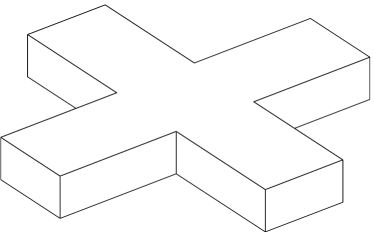
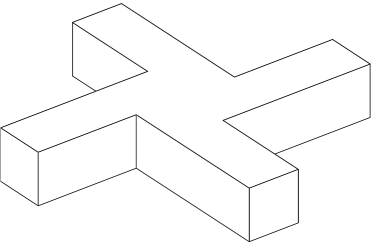
The principles outlined above have been applied to the design of optically-driven micromachine elements, and have proved successful (Knöner et al., 2007). The principles can also be recognised in successful devices that appear to be based on geometric optics principles, or even trial-and-error (Nieminen et al., 2006a). Figure 1 shows two very simple devices based on these principles. The achiral cross rotor is designed to be rotated by an incident beam carrying angular momentum, while the chiral rotor will rotate in an incident linearly polarised Gaussian beam. Viewing these structures as microholographic elements, they can be seen as binary phase approximations of interference patterns between paraxial Gaussian and LG04 beams. If both have planar wavefronts, the achiral rotor results, while if the Gaussian beam has curved wavefronts, the chiral rotor results. This suggests that the direction of rotation of the chiral rotor can be reversed by reversing the curvature of an incident Gaussian beam; this effect has been oberved by Galajda and Ormos (2002). Simple structures such as those shown in figure 1 have also been fabricated and tested (Ukita and Kanehira, 2002). The microhologram picture of these devices suggests that the optimum thickness is that which produces a half-wave phase difference between light that passes through the arms of the structure, and light that passes between them.
6 Optical measurement of optical torque
One disadvantage resulting from the use of orbital angular momentum to drive rotation is that while spin angular momentum is relatively easy to measure optically (Crichton and Marston, 2000; Nieminen et al., 2001; Bishop et al., 2003, 2004; La Porta and Wang, 2004), it is rather more difficult to optically measure orbital angular momentum. In principle, it should be possible to do so by a variety of methods, such as using holograms as mode filters (Mair et al., 2001; Parkin et al., 2004), interferometry using Dove prisms to introduce a phase shift (Leach et al., 2002), or measurement of the rotational frequency shift (Atkinson, 1935; Basistiy et al., 2003). While such methods have been demonstrated to be able to accurately measure optical torque (Parkin et al., 2004), accurate optical measurement of orbital torque within optical tweezers has proved elusive. This appears to largely result from sensitivity to alignment, both transverse and angular, and aberrations.
However, a method of estimating the orbital torque has been demonstrated (Parkin et al., 2006b, a), wherein the rotation rate and spin torque are measured for the same object being rotated by left- and right-circularly polarised beams, and a linearly polarised beam, all carrying the same orbital angular momentum. If the spin torque is similar in magnitude (the handedness will be opposite) for the two circularly polarised cases, and the difference in rotation rate as compared with the linearly polarised beam is also the same for the two, then we can safely assume that, as a reasonable approximation, the orbital torque is the same in all cases. The variation in rotation rate with the spin then allows the viscous drag to be measured. The orbital torque can then be estimated from the rotation rate in the linearly polarised beam.
It should be recalled that for particles with higher-order rotational symmetry (), the torques resulting from the incident left and right circularly polarized modes are independent of each other. Furthermore, such particles do not possess (linear) shape birefringence, and will therefore not alter the polarization of an incident linearly polarized beam. Therefore, the spin torques per photon from each of the left and right circularly polarized components of the beam must be equal in magnitude and opposite in direction; if the incident beam is linearly polarized, these torques must cancel.
So, although at first consideration, the above method for the measurement of the total angular momentum might strike the reader as a hopeful approximation, it appears that it is very likely to yield the correct result.
7 Conclusion
From general principles of symmetry, we have been able to deduce a number of features of the generation of optical torque and its dependence on the geometries of the particle and the beam. For an elongated or birefringent particle, whether rotated by plane polarised light, circularly polarised light, or by a beam with an elliptical focal spot, the shared symmetry results in similar behaviour in all of these cases.
Particles of higher-order rotational symmetry, such a microfabricated optically-driven rotors offer angle-independent torque, and the possibility of higher torques due to exploitation of orbital angular momentum. An important design choice is whether to use a chiral particle, for higher efficiency, or a nonchiral particle, for equal performance in either direction of rotation. The chiral particle has the advantage of rotating in a Gaussian beam, whereas the achiral particle requires a beam carrying orbital angular momentum for rotations. In either case, a particle with th order rotational symmetry is best driven by a focussed Laguerre–Gauss mode of helicity of .
It has been suggested in the past that the essentially unlimited angular momentum of optical vortices, with thousands of per photon being achievable, can be used for highly efficient optical rotation. This is not likely to be useful for the optical rotation of small objects, since such beams necessarily have focal spots hundreds of wavelengths across (if, however, one wishes to use an optical rotor that is hundreds of wavelengths across …). In general, the best efficiencies result from the use of focal spots almost the size of the particle, with as much power as possible in the higher angular momentum modes.
Finally, we can note that a randomly-selected irregular particle is almost certainly chiral, and should experience an optical torque when illuminated. Why, then, is optical torque regarded as unusual, if most randomly-chosen particles should experience torques? Although a torque might exist, it might also be very small; if smaller than torques associated with the rotational Brownian motion of the particle, the optical torque will not be noticeable. Rotation should be more readily observable in environments of low viscosity, such as particles in gas. Under such circumstances, rotation is observed (Ehrenhaft, 1945), although convection and thermophoresis may well be the dominant effects. Torques on random particles can also be maximised by high refractive index, increasing the reflectivity (Khan et al., 2006). However, most naturally occurring light is predominatly unpolarised, and as such can be represented as sums of VSWFs with . The same is the case for linearly polarised light. It is especially in this case that torques can result most readily in alignment rather than continuous spinning, which can also mask the presence of an optical torque.
References
- Allen et al. (1992) Allen, L., Beijersbergen, M. W., Spreeuw, R. J. C., Woerdman, J. P., 1992. Orbital angular momentum and the transformation of Laguerre-Gaussian laser modes. Physical Review A 45, 8185–8189.
- Allen et al. (1999) Allen, L., Padgett, M. J., Babiker, M., 1999. The orbital angular momentum of light. Progress in Optics 39, 291–372.
- Ashkin (1992) Ashkin, A., 1992. Forces of a single-beam gradient laser trap on a dielectric sphere in the ray optics regime. Biophysical Journal 61, 569–582.
- Ashkin (2000) Ashkin, A., 2000. History of optical trapping and manipulation of small-neutral particle, atoms, and molecules. IEEE Journal on Selected Topics in Quantum Electronics 6 (6), 841–856.
- Ashkin et al. (1986) Ashkin, A., Dziedzic, J. M., Bjorkholm, J. E., Chu, S., 1986. Observation of a single-beam gradient force optical trap for dielectric particles. Optics Letters 11, 288–290.
- Atkinson (1935) Atkinson, R. d’E., 1935. Energy and angular momentum in certain optical problems. Physical Review 47, 623–627.
- Barnett (2002) Barnett, S. M., 2002. Optical angular-momentum flux. Journal of Optics B: Quantum and Semiclassical Optics 4, S7–S16.
- Basistiy et al. (2003) Basistiy, I. V., Slyusar, V. V., Soskin, M. S., Vasnetsov, M. V., Bekshaev, A. Y., 2003. Manifestation of the rotational Doppler effect by use of an off-axis optical vortex beam. Optics Letters 28 (14), 1185–1187.
- Bayoudh et al. (2003) Bayoudh, S., Nieminen, T. A., Heckenberg, N. R., Rubinsztein-Dunlop, H., 2003. Orientation of biological cells using plane polarised Gaussian beam optical tweezers. Journal of Modern Optics 50 (10), 1581–1590.
- Benford and Konz (2004) Benford, G., Konz, C., 2004. Reply to comment on “Geometric absorption of electromagnetic angular momentum”. Optics Communications 235, 231–232.
- Beth (1936) Beth, R. A., 1936. Mechanical detection and measurement of the angular momentum of light. Physical Review 50, 115–125.
- Bishop et al. (2003) Bishop, A. I., Nieminen, T. A., Heckenberg, N. R., Rubinsztein-Dunlop, H., 2003. Optical application and measurement of torque on microparticles of isotropic nonabsorbing material. Physical Review A 68, 033802.
- Bishop et al. (2004) Bishop, A. I., Nieminen, T. A., Heckenberg, N. R., Rubinsztein-Dunlop, H., 2004. Optical microrheology using rotating laser-trapped particles. Physical Review Letters 92 (19), 198104.
- Bonin et al. (2002) Bonin, K. D., Kourmanov, B., Walker, T. G., 2002. Light torque nanocontrol, nanomotors and nanorockers. Optics Express 10 (19), 984–989.
- Born and Wolf (1997) Born, M., Wolf, E., 1997. Principles of Optics, 6th Edition. Cambridge University Press, Cambridge.
- Brock (2001) Brock, B. C., 2001. Using vector spherical harmonics to compute antenna mutual impedance from measured or computed fields. Sandia report SAND2000-2217-Revised, Sandia National Laboratories, Albuquerque, New Mexico, USA.
- Cheng et al. (2002) Cheng, Z., Chaikin, P. M., Mason, T. G., 2002. Light streak tracking of optically trapped thin microdisks. Physical Review Letters 89 (10), 108303.
- Courtial and Padgett (2000) Courtial, J., Padgett, M. J., 2000. Limit to the orbital angular momentum per unit energy in a light beam that can be focussed onto a small particle. Optics Communications 173, 269–274.
- Crichton and Marston (2000) Crichton, J. H., Marston, P. L., 2000. The measurable distinction between the spin and orbital angular momenta of electromagnetic radiation. Electronic Journal of Differential Equations Conf. 04, 37–50.
- Curtis and Grier (2003) Curtis, J. E., Grier, D. G., 2003. Structure of optical vortices. Physical Review Letters 90 (13), 133901.
- Ehrenhaft (1945) Ehrenhaft, F., 1945. Rotating action on matter in a beam of light. Science 101, 676–677.
- Friese et al. (1996) Friese, M. E. J., Enger, J., Rubinsztein-Dunlop, H., Heckenberg, N. R., 1996. Optical angular-momentum transfer to trapped absorbing particles. Physical Review A 54, 1593–1596.
- Friese et al. (1998) Friese, M. E. J., Nieminen, T. A., Heckenberg, N. R., Rubinsztein-Dunlop, H., 1998. Optical alignment and spinning of laser trapped microscopic particles. Nature 394, 348–350, erratum in Nature, 395, 621 (1998).
- Friese et al. (2001) Friese, M. E. J., Rubinsztein-Dunlop, H., Gold, J., Hagberg, P., Hanstorp, D., 2001. Optically driven micromachine elements. Applied Physics Letters 78, 547–549.
- Funk et al. (2008) Funk, M., Parkin, S. J., Stilgoe, A. B., Nieminen, T. A., Heckenberg, N. R., Rubinsztein-Dunlop, H., 2008. Constant power optical tweezers with controllable torque. To appear in Optics Letters.
- Galajda and Ormos (2001) Galajda, P., Ormos, P., 2001. Complex micromachines produced and driven by light. Applied Physics Letters 78, 249–251.
- Galajda and Ormos (2002) Galajda, P., Ormos, P., 2002. Rotors produced and driven in laser tweezers with reversed direction of rotation. Applied Physics Letters 80 (24), 4653–4655.
- He et al. (1995) He, H., Friese, M. E. J., Heckenberg, N. R., Rubinsztein-Dunlop, H., 1995. Direct observation of transfer of angular momentum to absorptive particles from a laser beam with a phase singularity. Physical Review Letters 75, 826–829.
- Heckenberg et al. (1999) Heckenberg, N. R., Friese, M. E. J., Nieminen, T., Rubinsztein-Dunlop, H., 1999. Mechanical effects of optical vortices. In: Vasnetsov, M., Staliunas, K. (Eds.), Optical Vortices. Vol. 228 of Horizons in World Physics. Nova Science Publishers, Commack, New York, pp. 75–105.
- Higurashi et al. (1997) Higurashi, E., Ohguchi, O., T. Tamamura, H. U., Sawada, R., 1997. Optically induced rotation of dissymmetrically shaped flourinated polyimide micro-objects in optical traps. Journal of Applied Physics 82, 2773–2779.
- Higurashi et al. (1994) Higurashi, E., Ukita, H., Tanaka, H., Ohguchi, O., 1994. Optically induced rotation of anisotropic micro-objects fabricated by surface micromachining. Applied Physics Letters 64 (17), 2209–2210.
- Holbourn (1936) Holbourn, A. H. S., 1936. Angular momentum of circularly polarised light. Nature 137, 31.
- Humblet (1943) Humblet, J., Jul. 1943. Sur le moment d’impulsion d’une onde électromagnétique. Physica 10 (7), 585–603.
- Jackson (1999) Jackson, J. D., 1999. Classical Electrodynamics, 3rd Edition. John Wiley, New York.
- Jauch and Rohrlich (1976) Jauch, J. M., Rohrlich, F., 1976. The Theory of Photons and Electrons, 2nd Edition. Springer, New York.
- Kahnert (2003) Kahnert, F. M., 2003. Numerical methods in electromagnetic scattering theory. Journal of Quantitative Spectroscopy and Radiative Transfer 79–80, 775–824.
- Kahnert (2005) Kahnert, M., 2005. Irreducible representations of finite groups in the t-matrix formulation of the electromagnetic scattering problem. Journal of the Optical Society of America A 22 (6), 1187–1199.
- Kelemen et al. (2006) Kelemen, L., Valkai, S., Ormos, P., 2006. Integrated optical motor. Applied Optics 45 (12), 2777–2780.
- Kepler (1619) Kepler, J., 1619. De Cometis Libelli Tres. Augustae Vindelicorum, Augsburg, in Latin.
- Khan et al. (2006) Khan, M., Sood, A. K., Deepak, F. L., Rao, C. N. R., 2006. Nanorotors using asymmetric inorganic nanorods in an optical trap. Nanotechnology 17, S287–S290.
- Knöner et al. (2007) Knöner, G., Parkin, S., Nieminen, T. A., Loke, V. L. Y., Heckenberg, N. R., Rubinsztein-Dunlop, H., 2007. Integrated optomechanical microelements. Optics Express 15 (9), 5521–5530.
- Knöner et al. (2006) Knöner, G., Rolfe, B. E., Campbell, J. H., Parkin, S. J., Heckenberg, N. R., Rubinsztein-Dunlop, H., 2006. Mechanics of cellular adhesion to artificial artery templates. Biophysical Journal 91, 3085–3096.
- Konz and Benford (2003) Konz, C., Benford, G., 2003. Geometric absorption of electromagnetic angular momentum. Optics Communications 226, 249–254.
- La Porta and Wang (2004) La Porta, A., Wang, M. D., 2004. Optical torque wrench: Angular trapping, rotation, and torque detection of quartz microparticles. Physical Review Letters 92 (19), 190801.
- Leach et al. (2002) Leach, J., Padgett, M. J., Barnett, S. M., Franke-Arnold, S., Courtial, J., 2002. Measuring the orbital angular momentum of a single photon. Physical Review Letters 88 (25), 257901.
- Loke et al. (2007) Loke, V. L. Y., Nieminen, T. A., Parkin, S. J., Heckenberg, N. R., Rubinsztein-Dunlop, H., 2007. FDFD/T-matrix hybrid method. Journal of Quantitative Spectroscopy and Radiative Transfer 106, 274–284.
- Mair et al. (2001) Mair, A., Vaziri, A., Weihs, G., Zeilinger, A., 2001. Entanglement of the orbital angular momentum states of photons. Nature 412, 313–316.
- Mishchenko (1991) Mishchenko, M. I., 1991. Light scattering by randomly oriented axially symmetric particles. Journal of the Optical Society of America A 8, 871–882.
- Mishchenko et al. (2000) Mishchenko, M. I., Hovenier, J. W., Travis, L. D. (Eds.), 2000. Light scattering by nonspherical particles: theory, measurements, and applications. Academic Press, San Diego.
- Moffitt et al. (2008) Moffitt, J. R., Chemla, Y. R., Smith, S. B., Bustamante, C., 2008. Recent advances in optical tweezers. Annual Review of Biochemistry 77, 205–228.
- Neale et al. (2005) Neale, S. L., MacDonald, M. P., Dholakia, K., Krauss, T. F., 2005. All-optical control of microfluidic components using form birefringence. Nature Materials 4, 530–533.
- Nieminen (2004) Nieminen, T. A., 2004. Comment on “Geometric absorption of electromagnetic angular momentum”, C. Konz, G. Benford. Optics Communications 235, 227–229.
- Nieminen et al. (2001) Nieminen, T. A., Heckenberg, N. R., Rubinsztein-Dunlop, H., 2001. Optical measurement of microscopic torques. Journal of Modern Optics 48, 405–413.
- Nieminen et al. (2006a) Nieminen, T. A., Higuet, J., Knöner, G., Loke, V. L. Y., Parkin, S., Singer, W., Heckenberg, N. R., Rubinsztein-Dunlop, H., 2006a. Optically driven micromachines: progress and prospects. Proc. SPIE 6038, 237–245.
- Nieminen et al. (2007a) Nieminen, T. A., Knöner, G., Heckenberg, N. R., Rubinsztein-Dunlop, H., 2007a. Physics of optical tweezers. Methods in Cell Biology 82, 207–236.
- Nieminen et al. (2007b) Nieminen, T. A., Knöner, G., Heckenberg, N. R., Rubinsztein-Dunlop, H., 2007b. Physics of optical tweezers. In: Berns, M. W., Greulich, K. O. (Eds.), Laser Manipulation of Cells and Tissues. Vol. 82 of Methods in Cell Biology. Elsevier, Ch. 6, pp. 207–236.
- Nieminen et al. (2006b) Nieminen, T. A., Loke, V. L. Y., Brańczyk, A. M., Heckenberg, N. R., Rubinsztein-Dunlop, H., 2006b. Towards efficient modelling of optical micromanipulation of complex structures. PIERS Online 2 (5), 442–446.
- Nieminen et al. (2007c) Nieminen, T. A., Loke, V. L. Y., Stilgoe, A. B., Knöner, G., Brańczyk, A. M., Heckenberg, N. R., Rubinsztein-Dunlop, H., 2007c. Optical tweezers computational toolbox. Journal of Optics A: Pure and Applied Optics 9, S196–S203.
- Nieminen et al. (2008a) Nieminen, T. A., Parkin, S., Asavei, T., Loke, V. L., Heckenberg, N. R., Rubinsztein-Dunlop, H., 2008a. Optical vortex trapping and the dynamics of particle rotation. In: Andrews, D. L. (Ed.), Structured Light and Its Applications: An Introduction to Phase-Structured Beams and Nanoscale Optical Forces. Elsevier, Amsterdam, Ch. 8, pp. 195–236.
- Nieminen et al. (2004) Nieminen, T. A., Parkin, S. J., Heckenberg, N. R., Rubinsztein-Dunlop, H., 2004. Optical torque and symmetry. Proc. SPIE 5514, 254–263.
- Nieminen et al. (2003a) Nieminen, T. A., Rubinsztein-Dunlop, H., Heckenberg, N. R., 2003a. Calculation of the t-matrix: general considerations and application of the point-matching method. Journal of Quantitative Spectroscopy and Radiative Transfer 79-80, 1019–1029.
- Nieminen et al. (2003b) Nieminen, T. A., Rubinsztein-Dunlop, H., Heckenberg, N. R., 2003b. Multipole expansion of strongly focussed laser beams. Journal of Quantitative Spectroscopy and Radiative Transfer 79-80, 1005–1017.
- Nieminen et al. (2008b) Nieminen, T. A., Stilgoe, A. B., Heckenberg, N. R., Rubinsztein-Dunlop, H., 2008b. Angular momentum of a strongly focused Gaussian beam. Journal of Optics A: Pure and Applied Optics 10, 115005.
- Nienhuis (2008) Nienhuis, G., 2008. Angular momentum and vortices in optics. In: Andrews, D. L. (Ed.), Structured Light and Its Applications: An Introduction to Phase-Structured Beams and Nanoscale Optical Forces. Elsevier, Amsterdam, Ch. 2, pp. 19–62.
- Noether (1918) Noether, E., 1918. Invariante Variationsprobleme. Nachrichten von der Gesselschaft der Wissenschaften zu Göttingen, Mathematisch-Physikalische Klasse 1918, 235–257, english translation by M. A. Tavel, Transport Theory and Statistical Mechanics 1(3), 183-207 (1971), arXiv:physics/0503066.
- Parkin et al. (2006a) Parkin, S., Knöner, G., Nieminen, T. A., Heckenberg, N. R., Rubinsztein-Dunlop, H., 2006a. Measurement of the total optical angular momentum transfer in optical tweezers. Optics Express 14 (15), 6963–6970.
- Parkin et al. (2006b) Parkin, S. J., Knöner, G., Nieminen, T. A., Heckenberg, N. R., Rubinsztein-Dunlop, H., 2006b. Torque transfer in optical tweezers due to orbital angular momentum. Proc. SPIE 6326, 63261B.
- Parkin et al. (2007) Parkin, S. J., Knöner, G., Nieminen, T. A., Heckenberg, N. R., Rubinsztein-Dunlop, H., 2007. Picoliter viscometry using optically rotated particles. Physical Review E 76, 041507.
- Parkin et al. (2004) Parkin, S. J., Nieminen, T. A., Heckenberg, N. R., Rubinsztein-Dunlop, H., 2004. Optical measurement of torque exerted on an elongated object by a noncircular laser beam. Physical Review A 70, 023816.
- Pfeifer et al. (2006) Pfeifer, R. N. C., Nieminen, T. A., Heckenberg, N. R., Rubinsztein-Dunlop, H., 2006. Two controversies in classical electromagnetism. Proc. SPIE 6326, 63260H.
- Poynting (1909) Poynting, J. H., 1909. The wave motion of a revolving shaft, and a suggestion as to the angular momentum in a beam of circularly polarised light. Proc. R. Soc. Lond. A 82, 560–567.
- Rose (1957) Rose, M. E., 1957. Elementary theory of angular momentum. Wiley, New York.
- Simpson et al. (1997) Simpson, N. B., Dholakia, K., Allen, L., Padgett, M. J., 1997. Mechanical equivalence of spin and orbital angular momentum of light: an optical spanner. Optics Letters 22, 52–54.
- Soper (1976) Soper, D. E., 1976. Classical Field Theory. Wiley, New York.
- Stewart (2005) Stewart, A. M., 2005. Angular momentum of the electromagnetic field: the plane wave paradox resolved. European Journal of Physics 26, 635–641.
- Stilgoe et al. (2008) Stilgoe, A. B., Nieminen, T. A., Knöner, G., Heckenberg, N. R., Rubinsztein-Dunlop, H., 2008. The effect of mie resonances on trapping in optical tweezers. Optics Express 16 (19), 15039–15051.
- Ukita and Kanehira (2002) Ukita, H., Kanehira, M., 2002. A shuttlecock optical rotator—its design, fabrication and evaluation for a microfluidic mixer. IEEE Journal on Selected Topics in Quantum Electronics 8 (1), 111–117.
- Varshalovich et al. (1988) Varshalovich, D. A., Moskalev, A. N., Khersonskii, V. K., 1988. Quantum theory of angular momentum. World Scientific, Singapore.
- Waterman (1971) Waterman, P. C., 1971. Symmetry, unitarity, and geometry in electromagnetic scattering. Physical Review D 3, 825–839.
- Williams and Rouzina (2002) Williams, M. C., Rouzina, I., 2002. Force spectroscopy of single DNA and RNA molecules. Current Opinion in Structural Biology 12, 330–336.
- Worrall (1982) Worrall, J., 1982. The pressure of light: The strange case of the vacillating ‘crucial experiment’. Stud. Hist. Phil. Sci. 13 (2), 133–171.
- Zambrini and Barnett (2005) Zambrini, R., Barnett, S. M., 2005. Local transfer of optical angular momentum to matter. Journal of Modern Optics 52 (8), 1045–1052.