Electron acceleration at a low-Mach-number perpendicular collisionless shock
Abstract
A full particle simulation study is carried out on the electron acceleration at a collisionless, relatively low Alfven Mach number (), perpendicular shock. Recent self-consistent hybrid shock simulations have demonstrated that the shock front of perpendicular shocks has a dynamic rippled character along the shock surface of low-Mach-number perpendicular shocks. In this paper, the effect of the rippling of perpendicular shocks on the electron acceleration is examined by means of large-scale (ion-scale) two-dimensional full particle simulations. It has been shown that a large-amplitude electric field is excited at the shock front in association with the ion-scale rippling, and that reflected ions are accelerated upstream at a localized region where the shock-normal electric field of the rippled structure is polarized upstream. The current-driven instability caused by the highly-accelerated reflected ions has a high growth rate to large-amplitude electrostatic waves. Energetic electrons are then generated by the large-amplitude electrostatic waves via electron surfing acceleration at the leading edge of the shock transition region. The present result suggests that the electron surfing acceleration is also a common feature at low-Mach-number perpendicular collisionless shocks.
Subject headings:
acceleration of particles — plasmas — shock waves —1. Introduction
Collisionless shocks are universal processes in space and are observed in laboratory, astrophysical, and space plasmas, including astrophysical jets, an interstellar medium, the heliosphere, and planetary magnetospheres. Particle acceleration is a common feature of at collisionless shocks, but is still a major unresolved issue. The most plausible mechanism of the acceleration is the diffusive shock acceleration (DSA), which explains broadband power-law spectrum with an index around 2 (Drury, 1983; Blandford & Eichler, 1987). Before the DSA phase in which electrons cross the shock front many times, they have to be pre-accelerated by unknown injection mechanism. Such “injection problem” is still unresolved.
One of the possible injection mechanisms for electrons is the electron surfing acceleration by electrostatic fields (Katsouleas & Dawson, 1983; Shimada & Hoshino, 2000; Hoshino & Shimada, 2002). Shimada & Hoshino (2000) performed a one-dimensional (1D) electromagnetic full particle simulation and found the formation of large-amplitude electrostatic solitary structures during the cyclic reformation of a high-Mach-number perpendicular shock in a low-beta and weakly magnetized plasma. The coherent solitary structures trap electrons in their electrostatic potential well, resulting in significant surfing acceleration of electrons.
So far, the electron surfing acceleration has been argued for high-Mach-number shocks, and studied by many authors (e.g., McClements et al., 2001; Hoshino & Shimada, 2002; Schmitz et al., 2002a, b; Amano & Hoshino, 2007). A typical astrophysical example of such high-Mach-number shocks is the young supernova remnant (SNR), which is thought to be an accelerator of high-energy electrons, emitting bright synchrotron radiation in radio and X-ray bands at shocks with Mach number of (e.g., Koyama et al., 1995; Bamba et al., 2003, 2005). However, in many astrophysical environments, the electron acceleration at lower-Mach-number () shocks is inferred from observations and/or expected theoretically. Possible examples are old SNRs or old SNRs interacting with giant molecular clouds (Claussen et al., 1997; Chevalier, 1999; Bykov et al., 2000; Yamazaki et al., 2006; Brogan et al., 2006), merging galaxy clusters (Markevitch et al., 2002), AGN outbursts at the galaxy clusters (Fujita et al., 2007), and so on. The electron acceleration is also observed at Earth’s bow shock even with a low Mach number of (Oka et al., 2006). Hence it is interesting to ask whether the electron surfing acceleration can occur at lower-Mach-number shocks or not.
It has been demonstrated by one-dimensional full particle simulations that the electron surfing acceleration takes place at a relatively-high-Mach-number shock of but not at a very-low-Mach-number shock of (e.g., Shimada & Hoshino, 2000; Schmitz et al., 2002a). 111 Note that in the full particle simulations, a reduced ion-to-electron mass ratio of –25, is usually adopted for computational efficiency. In general, different mass ratio sometimes changes the simulation results qualitatively, and the simulation results with a reduced mass ratio cannot be directly compared with astrophysical phenomena or results of hybrid simulations. Therefore, to avoid a confusion, we use a notation for the Mach number of shocks with a reduced mass ratio, while we use another notation for the real mass ratio. However, these previous works on the electron surfing acceleration are mainly based on 1D simulations, in which configuration of shock magnetic fields cannot be modified.
It is well known from resuts of two-dimensional hybrid-code simulations that there exist large-amplitude fluctuations in the magnetic field and density of the shock transition region of lower-Mach-number shocks () (Winske & Quest, 1988). These fluctuations at the shock surface have been analyzed in terms of turbulent “ripples” (Lowe & Burgess, 2003; Burgess, 2006a). Burgess (2006b) has demonstrated, using a combination of self-consistent hybrid simulation and test particle calculation, that energetic electrons are produced by both magnetic mirroring by the rippled structure and by stochastic acceleration by magnetic fluctuations keeps particles within the shock transition region. However, electron-scale microscopic instabilities, i.e., current driven instabilities are neglected in the combination of hybrid simulation and test-particle calculation. Hence multi-dimensional full particle simulations are necessary for studying the effect of ion-scale rippling of a perpendicular shock on the electron surfing acceleration.
The purpose of this paper is to examine the effect of the dynamic rippled structuring of the shock front on electron acceleration processes by the first-principle full particle simulation. In order to take into account the rippling of a perpendicular shock, simulation domain is taken to be larger than the ion inertial length.
The paper is organized as follows. Section 2 describes the model and the parameters of the full particle simulation. Section 3 demonstrates the ion-scale structure of a perpendicular shock found in the full particle simulations and the resulting electron acceleration. Finally, section 4 gives summary of this paper.
2. Full Particle Simulation
In this paper, a collisionless shock is excited with the “relaxation method” (e.g., Leroy et al., 1981, 1982; Umeda & Yamazaki, 2006; Umeda et al., 2008) in which the simulation domain is taken in the rest frame of the excited shock. Generally speaking, it is not easy to perform a large-scale (ion-scale) multi-dimensional full particle simulations of collisionless shocks even with present-day supercomputers. This is because a shock wave excited by conventional method becomes unsteady relative to the simulation domain. Very recently, however, a two-dimensional shock-rest-frame model has been successfully developed by Umeda et al. (2008), which is important to be able to follow the shock for a long time with a limited computer resource.
We use a 2D electromagnetic particle code (Umeda, 2004), in which the full set of Maxwell’s equations and the relativistic equation of motion for individual electrons and ions are solved in a self-consistent mannar. The continuity equation for charge is also solved to compute the exact current density given by the motion of charged particles (Umeda et al., 2003).
The initial state consists of two uniform regions separated by a discontinuity. In the upstream region that is taken in the left hand side of the simulation domain, electrons and ions are distributed uniformly in space and are given random velocities to approximate shifted Maxwellian momentum distributions with the drift velocity , number density , isotropic temperatures and , where , , and are the mass, charge, plasma frequency and thermal velocity, respectively. Subscripts “1” and “2” denote “upstream” and “downstream”, respectively. The upstream magnetic field is also assumed to be uniform, where is the cyclotron frequency (with sign included). The downstream region taken in the right-hand side of the simulation domain is prepared similarly with the drift velocity , density , isotropic temperatures and , and magnetic field .
We take the simulation domain in the - plane and assume a perpendicular shock (i.e., ). Since the ambient magnetic field is taken in the direction, free motion of particles along the ambient magnetic field is taken into account. As a motional electric field, a uniform external electric field is applied in both upstream and downstream regions, so that both electrons and ions drift in the direction. At the left boundary of the simulation domain in the direction, we inject plasmas with the same quantities as those in the upstream region, while plasmas with the same quantities as those in the downstream region are also injected from the right boundary in the direction. We adopted absorbing boundaries to suppress non-physical reflection of electromagnetic waves at both ends of simulation domain in the direction (Umeda et al., 2001), while the periodic boundaries are imposed in the direction.
The initial downstream quantities are given by solving the shock jump conditions for a magnetized two-fluid isotropic plasma consisting of electrons and ions (e.g., Hudson, 1970),
| (1) | |||
| (2) | |||
| (3) | |||
| (4) |
where . In order to determine a unique initial downstream state, we need given upstream quantities , , , , and and an additional parameter. We assume a low-beta and weakly-magnetized plasma such that and in the upstream region. We also use a reduced ion-to-electron mass ratio for computational efficiency. The light speed and the bulk flow velocity of the upstream plasma are also assumed. Then, the Alfvén Mach number is calculated as . The ion-to-electron temperature ratio in the upstream region is given as . In this study, downstream ion-to-electron temperature ratio is also assumed as another initial parameter to obtain the unique downstream quantities by solving the above four equations, , , , and .
In this study, we perform two runs with different sizes of the simulation domain. We use cells for the upstream region and cells for the downstream region, respectively, in Run A. The grid spacing and time step of the present simulation are and , respectively. Here is the electron Debye length upstream. Thus the total size of the simulation domain is which is long enough to include the ion-scale rippled structure, where is the ion inertial length. In Run B, we use cells for the upstream region and cells for the downstream region, respectively. Thus the the total size of the simulation domain is , in which ion-scale processes along the ambient magnetic field is neglected. We used 16 pairs of electrons and ions per cell in the upstream region and 64 pairs of electrons and ions per cell in the downstream region, respectively, at the initial state.
3. Result
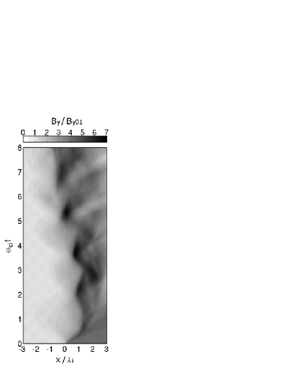
Figure 1 shows the transverse magnetic field as a function of position and time averaged over the direction for Run A. The position and time are renormalized by the ion inertial length and the ion cyclotron period , respectively. The magnitude is normalized by the initial upstream magnetic field . In the present shock-rest-frame model, a shock wave is excited by the relaxation of the two plasmas with different quantities. Figure 1 shows that the shock front appears and disappears at a timescale of the downstream ion gyro-period, which corresponds to the cyclic reformation of perpendicular shocks. Since the initial state is given by the shock jump conditions for a two-fluid plasma consisting of electrons and ions, the excited shock is “almost” at rest in the simulation domain.
We have also performed a 1D simulation with the same parameter as the 2D simulations and confirmed that the period of cyclic reformation in all simulation runs (Runs A, B, and 1D) is the same. However, the peak amplitude of the overshooting magnetic field in Run A is about , while this is about in Run B and in the 1D run. We have also confirmed that the cyclic reformation becomes less significant for in Run A, while the cyclic reformation continues for a long time in Run B and in the 1D run. The present result is in agreement with the recent 2D full-particle simulations of a low-Mach number shock, in which it has been demonstrated that the perpendicular shock evolves from the cyclic reformation phase to the “nonlinear whistler” phase in 2D simulations with the in-plane magnetic field (Hellinger et al., 2007; Lembege et al., 2008).
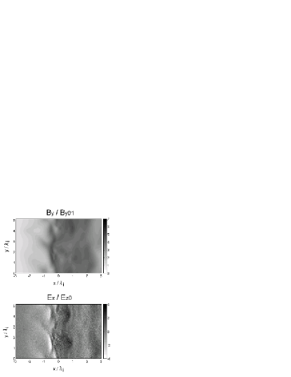
In the present study we focus on the particle acceleration in the cyclic reformation phase. Figure 2 shows the rippled structure of the perpendicular shock at . The top panel shows a gray-scale map of the magnetic field magnitude , and the bottom panel shows a gray-scale map of the electric field magnitude around the shock transition region. The magnitude of magnetic field is normalized by the initial upstream magnetic field , while the magnitude of electric field is normalized by the motional electric field .
We found a strong fluctuation in the magnetic field component at the shock surface. The amplitude of the fluctuation is estimated as , which is larger than the magnitude of the upstream magnetic field. The wavelength of the fluctuation is several ion inertial length. This strong fluctuation has been analyzed by Lowe & Burgess (2003) in terms of ripples at the shock overshoot.
We computed a numerical frequency-wavenumber spectrum by taking Fourier transformation of the magnetic field component (not shown) and obtained a similar spectrum to the result by Lowe & Burgess (2003). The generation mechanism of the ripples is thought to be the ion perpendicular temperature anisotropy in the shock transition region, which drives Alfven ion cyclotron (L-mode) or mirror mode waves. Note that there is not any rippled structure in Run B because the size of the simulation domain in the magnetic field () direction is shorter than the ion inertial length. The overshoot magnetic field is uniform along the magnetic field in Run B and its magnitude is about , which is equal to the average overshoot magnetic field in Run A.
Around the shock front (), we also found a strong negative electric field with a magnitude of (see the bottom panel of Figure 2). This strong negative electric field at the shock front reflects ions upstream. Such a negative electric field is also found in Run B, but its magnitude is much smaller, about . There is a good correlation between the structure of and at the shock front as seen in Figure 2, implying that the strong negative electric field is associated with the rippled structure.
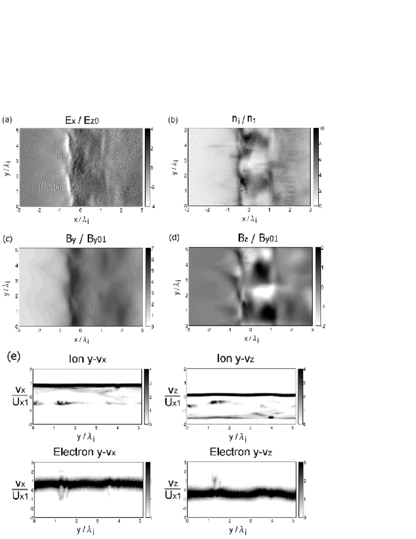
The effect of the acceleration of reflected ions is analyzed in Figure 3. The electric field magnitude at for Run A is shown in Figure 3a. At (-1.0,1.5) and (-1.0,3.5), we found wave structures with a short wavelength, which corresponds to electrostatic waves excited by the current-driven instability due to reflected ions. An interesting result here is that the electrostatic waves are not excited uniformly in the direction but are excited in localized regions. It is suggested that the localized excitation of the electrostatic waves is due to the strong negative shock-normal electric field at the shock front that accelerates reflected ions upstream.
The strong negative shock-normal electric field is associated with the rippled strucuture. Figures 3c and 3d show the mangetic field components and at for Run A. We have analyzed the Hall electric field and found that the term of is dominant. In other words, the strong negative shock-normal electric field is due to the magnetic pressure gradient force of the componet around arising from the rippled structure. Here, the excitation of electrostatic waves is discussed in terms of the particle distributions shown in Figures 3b and 3e.
Figure 3b shows the ion density normalized by the upstream density . Around 0.2, 2.0, and 3.2, we found the enhancement of the ion density that exceeds . In these regions, the magnitude of the magnetic field becomes lower (see in Figure 3c) to keep the pressure balance.
The left panels of Figure 3e show phase-space plots of ions and electrons. Around 0, 1.5, and 3.5, we found ion components with negative velocity, which correspond to reflected ions. The electrostatic waves around 1.5 and 3.5 are excited by the localized reflected ions. The patchy reflected ion beams are formed by the localized negative shock-normal electric field around .
Around 0, despite a strong shock-normal electric field, electrostatic waves are not strongly excited, either. This is because of small number of ions. We need a strong ion current in the direction to enhance the current-driven instability. That is, the velocity of reflected ions should be high and/or the number of reflected ions should be high to excite the patchy electrostatic waves.
In the phase-space plots in the right panels, nonthermal components of electrons are found at 1.5, where electrostatic waves are strongly enhanced. The existence of nonthermal components in is the evidence of the electron surfing acceleration at low-Mach-number perpendicular shock with . The electron surfing acceleration takes place in a localized region where a negative shock-normal current due to reflected ions is strongly enhanced.
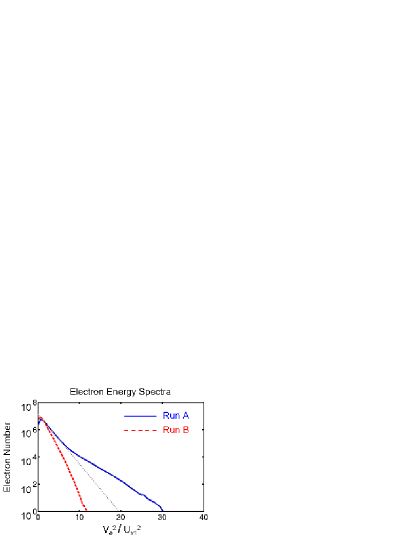
Figure 4 shows energy distribution functions of electrons in the downstream region for Runs A and B. The solid line shows the result of Run A, and the dashed line shows the result of Run B. Firstly, we found nonthermal electrons in Run A while there is no nonthermal electrons in Run B. Secondly, the downstream temperature in Runs A and B is very different, indicating the existence of additional electron energization mechanism in Run A, i.e., rippling of the perpendicular shock discussed by Burgess (2006b). We have also performed a 1D simulation run and confirmed that the electron energy spectrum is essentially the same as that in Run B.
The electron energy distribution for Run B (dashed line) corresponds to the Maxwellian distribution function with thermal velocity of , which can be explained by the plasma heating by magnetic compression. On the other hand, the thermal component of electron energy distribution for Run A (dotted line) corresponds to the Maxwellian distribution function with thermal velocity of . In addition, the maximum energy of electrons reaches in Run A.
The rippled structure can further energize electrons as discussed by Burgess (2006b), which can explain the Maxwellian distribution for Run A. In the shock foot region (), the magnitude of the magnetic field is . The average amplitude of electrostatic waves excited by the current-driven instability is . Thus the maximum energy of non-thermal electrons becomes about via the electron surfing acceleration as indicated from the and phase-space plots shown in Figure 3e. Thus there is three effects for energization of non-thermal electrons: The first is the electron surfing acceleration; The second is the magnetic compression at the shock overshoot (e.g., Shimada & Hoshino, 2000; Schmitz et al., 2002a; Umeda & Yamazaki, 2006). The third is the scattering by ion-scale rippled structure (Burgess, 2006b). To reach the maximum energy of all the three effects are needed.
Both in Run B and in the 1D run, the current-driven instability due to reflected ions excites electrostatic waves with amplitude of . However, this amplitude is not enough for the electron surfing acceleration. By contrast, the amplitude of the locally-excited electrostatic wave exceeds in Run A as shown in Figure 3a, and energetic electrons are generated by the electron surfing acceleration. This result suggests that microscopic current-driven instability enhanced by the ion-scale rippled structure of the low-Mach-number perpendicular shock generates nonthermal electrons, as observed in moderate-Mach-number perpendicular shocks of (e.g. Shimada & Hoshino, 2000; Hoshino & Shimada, 2002; Schmitz et al., 2002a, b; Amano & Hoshino, 2007).
4. Summary and Discussion
We have studied electron acceleration at a low-Mach-number perpendicular collisionless shock by performing two-dimensional full particle simulations. In order to take into account the effect of the rippling of a perpendicular shock (Lowe & Burgess, 2003; Burgess, 2006a, b), the simulation domain is taken to be larger than the ion inertial scale by using the shock-rest-frame model (Umeda et al., 2008). In the previous works, the electron acceleration by electron-scale microscopic instabilities at low-Mach-number perpendicular shocks has not focused on because the electron surfing acceleration by electrostatic waves (e.g., Shimada & Hoshino, 2000; Hoshino & Shimada, 2002), which is one of the possible injection mechanisms for electrons, is thought to be effective only in high-Mach-number perpendicular shocks. The present result suggests, by contrast, that the electron surfing acceleration is also a common feature at a perpendicular shock with .
The mechanism for generation of high-energy electrons is quite simple, and is summarized as follows: The perpendicular shock forms the rippled structures by ion temperature anisotropy; The rippled structures excite a strong electric field component in the shock-normal direction; Reflected ions in the shock transition region is strongly accelerated upstream by the electric field component of rippled structures; The strongly-accelerated reflected ions give a high growth rate of a current-driven instability to large-amplitude electrostatic waves in a localized region; Energetic electrons are generated by the electrostatic waves via surfing acceleration. Finally, high-energy non-thermal electrons are generated by both magnetic compression and scattering by ion-scale rippled structure in the shock transition region.
It has been demonstrated that multi-dimensionality sometimes weakens the electron surfing acceleration in the 2D simulations of uniform plasma models (e.g., Dieckmann & Shukla, 2006; Ohira & Takahara, 2007) and self-consistent shock models (e.g., Dieckmann et al., 2008; Umeda et al., 2008). Very recently, however, Amano & Hoshino (2008) have found the electron surfing acceleration in 2D simulation of a perpendicular shock with out-of-plane magnetic field. In their 2D simulation, the simulation domain is taken to be much larger than the ion inertial length along the shock surface, and kinetic effects of ions are fully included. The present result is another example showing the effect of ion kinetics to the electron surfing acceleration. It has been confirmed that the cross-scale coupling between an ion-scale mesoscopic instability and an electron-scale microscopic instability is important. Hence, a large-scale full particle simulation would be essential for studies of the electron acceleration at collisionless shocks.
Finally let us discuss on the reduced mass ratio. In the present simulation with , , and , the Buneman-type mode becomes unstable at when we use a reduced mass ratio of . When we use the real mass ratio of , the thermal velocity of upstream electrons becomes about 8.6 times as large as the case of , the self-reformation process is suppressed and the Buneman-type mode is also stabilized (Scholer & Matsukiyo, 2004). To make the Buneman-type mode unstable the electron thermal velocity must be smaller than the relative velocity between incoming electrons and reflected ions. Thus the present simulation result can be applied to a much lower beta of .
References
- Amano & Hoshino (2007) Amano, T., & Hoshino, M. 2007, ApJ, 661, 190
- Amano & Hoshino (2008) Amano, T., & Hoshino, M. 2008, ApJ, in press
- Bamba et al. (2003) Bamba, A., Yamazaki, R., Ueno, M., and Koyama, K. 2003, ApJ, 589, 827
- Bamba et al. (2005) Bamba, A., et al. 2005, ApJ, 621, 793
- Blandford & Eichler (1987) Blandford, R. D. & Eichler, D. 1987, Phys. Rep. 154, 1
- Brogan et al. (2006) Brogan, C. L. et al. 2006, ApJ, 639, L25
- Burgess (2006a) Burgess, D. 2006a, J. Geophys. Res., 111, A10210
- Burgess (2006b) Burgess, D. 2006b, ApJ, 653, 316
- Bykov et al. (2000) Bykov, A. M. et al. 2000, ApJ, 538, 203
- Claussen et al. (1997) Claussen, M. J. et al. 1997, ApJ, 489, 143
- Chevalier (1999) Chevalier, R. A. 1999, ApJ, 511, 798
- Dieckmann & Shukla (2006) Dieckmann, M., & Shukla, P. K. 2006, Plasma Phys. Controll Fusion, 48, 1515.
- Dieckmann et al. (2008) Dieckmann, M. E., Meli, A., Shukla, P. K., Drury, L. O. C. & Mastichiadis, A. 2008, Plasma Phys. Controll Fusion, 50, 065020.
- Drury (1983) Drury, L. O’C. 1983, Rep. Prog. Phys. 46, 973
- Fujita et al. (2007) Fujita, Y. et al. 2007, ApJ, 663, L61
- Hellinger et al. (2007) Hellinger, P., Travnicek, P., Lembege, B., & Savoini P. 2007, Geophys. Res. Lett., 34, L14109
- Hoshino & Shimada (2002) Hoshino, M. & Shimada, N. 2002, ApJ, 572, 880
- Hudson (1970) Hudson, P. D. 1970, Planet. Space Sci., 18, 1611
- Katsouleas & Dawson (1983) Katsouleas, T., & Dawson, J. M. 1983, Phys. Rev. Lett., 51, 392
- Koyama et al. (1995) Koyama, K. et al. 1995, Nature, 378, 255
- Lee et al. (2004) Lee, R. E., Chapman, S. C., & Dendy, R. O. 2004, ApJ, 604, 187
- Lembege et al. (2008) Lembege, B., Savoini, B., Hellinger, P., & Travnicek, P. M. 2008, J. Geophys. Res., in press
- Leroy et al. (1981) Leroy, M. M., Goodrich, C. C., Winske, D., Wu, C. S. & Papadopoulos, K. 1981, Geophys. Res. Lett., 8, 1269
- Leroy et al. (1982) Leroy, M. M., Winske, D., Goodrich, C. C., Wu, C. S. & Papadopoulos, K. 1982, J. Geophys. Res., 87, 5081
- Lowe & Burgess (2003) Lowe, R. E., & Burgess, D. 2003, Ann. Geophys. 21, 671
- Markevitch et al. (2002) Markevitch, M. et al. 2002, ApJ, 567, L27
- McClements et al. (2001) McClements, K. G., Dieckmann, M. E., Ynnerman, A., Chapman, S. C., & Dendy, R. O. 2001, Phys. Rev. Lett., 87, 255002
- Ohira & Takahara (2007) Ohira, Y., & Takahara, F. 2007, ApJ, 661, L171
- Oka et al. (2006) Oka, M. et al. 2006, Geophys. Res. Lett., 33, L24104
- Schmitz et al. (2002a) Schmitz, H., Chapman, S. C., & Dendy, R. O. 2002a, ApJ, 570, 637
- Schmitz et al. (2002b) Schmitz, H., Chapman, S. C., & Dendy, R. O. 2002b, ApJ, 579, 327
- Scholer & Matsukiyo (2004) Scholer, M., & Matsukiyo, S. 2004, Ann. Geophys. 22, 2345
- Shimada & Hoshino (2000) Shimada N., & Hoshino, M. 2000, ApJ, 543, L67
- Umeda (2004) Umeda, T. 2004, Ph.D. Thesis, Kyoto University
- Umeda et al. (2001) Umeda, T., Omura, Y., & Matsumoto, H. 2001, Comput. Phys. Commun., 137, 286
- Umeda et al. (2003) Umeda, T., Omura, Y., Tominaga, T., & Matsumoto, H. 2003, Comput. Phys. Commun., 156, 73
- Umeda & Yamazaki (2006) Umeda, T., & Yamazaki, R. 2006, Earth Planets Space, 58, e41 (arXiv:physics/0607220)
- Umeda et al. (2008) Umeda, T., Yamao, M., & Yamazaki, R. 2008, ApJ, 681, L85
- Winske & Quest (1988) Winske, D., & Quest, K. B. 1988, J. Geophys. Res., 93, 9681
- Yamazaki et al. (2006) Yamazaki, R. et al. 2006, MNRAS, 371, 1975