Laser-driven high-power X- and gamma-ray ultra-short pulse source
Abstract
A novel ultra-bright high-intensity source of X-ray and gamma radiation is suggested. It is based on the double Doppler effect, where a relativistic flying mirror reflects a counter-propagating electromagnetic radiation causing its frequency multiplication and intensification, and on the inverse double Doppler effect, where the mirror acquires energy from an ultra-intense co-propagating electromagnetic wave. The role of the flying mirror is played by a high-density thin plasma slab accelerating in the radiation pressure dominant regime. Frequencies of high harmonics generated at the flying mirror by a relativistically strong counter-propagating radiation undergo multiplication with the same factor as the fundamental frequency of the reflected radiation, approximately equal to the quadruple of the square of the mirror Lorentz factor.
pacs:
52.38.Ph - X-ray, gamma-ray and particle generation; 52.59.Ye - Plasma devices for generation of coherent radiation; 52.38.-r - Laser-plasma interactions; 52.35.Mw - Nonlinear phenomena: waves, wave propagation, and other interactions (including parametric effects, mode coupling, ponderomotive effects, etc.); 52.27.Ny - Relativistic plasmasI Introduction
An electromagnetic wave reflected off a moving mirror undergoes frequency multiplication and corresponding increase in the electric field magnitude. This phenomenon sometimes called the double Doppler effect was discussed by A. Einstein in his seminal paper bib:Einstein where the frequency multiplication factor was calculated as an example of the use of Lorentz transformations. The multiplication factor is approximately proportional to the square of the Lorentz factor of the mirror, making this effect an attractive basis for a source of powerful high-frequency radiation. In relativistic plasma, the double Doppler effect manifests itself when a fast change of the electric current density leads to the conversion of an incident light into strongly compressed pulses of high-frequency electromagnetic radiation.
Pulse compression and frequency upshifting can be seen in a broad variety of configurations, bib:Rev . A specular reflection can be afforded by a sufficiently dense relativistic electron cloud as suggested in Refs. bib:Landecker-52 ; bib:Ostr ; a less dense bunch of relativistic electrons causes the backward Thomson scattering as discussed in Refs. bib:Arutyunian-63 . The reflection at the moving ionization fronts was studied in Refs. bib:Semenova-67 . Further examples of the manifestation of the double Doppler effect in plasma whose dynamics is governed by the strong collective fields are seen in the concepts of the sliding mirror bib:SM , oscillating mirror bib:OscM ; bib:FOIL and flying mirror bib:FM which can produce ultra-short pulses of XUV radiation and X-ray.
The sliding mirror is formed by a thin foil whose density is so high that the electrons are confined whithin the boundaries of the ion layer. Irradiated by a relativistically strong laser pulse, which is not capable to quickly break the confinement condition, these electrons perform nonlinear motion along the foil, enriching the (partially) reflected radiaiton (as well as transmitted radiation) with high harmonics, bib:SM . In a less dense foil the electrons can perform collective motion in the direction perpendicular to the foil, thus forming a mirror oscillating with relativistic velocity. A portion of an incident relativistically strong electromagnetic wave, driving the oscillating mirror, is reflected in the form of strongly distorted wave carrying high harmonics, bib:OscM ; bib:FOIL ; bib:OscM2 .
In the flying mirror concept bib:FM , the role of the mirror is played by the electron density modulations in a strongly nonlinear Langmuir wave excited by an intense laser pulse (driver) in its wake in underdense plasma. A relatively weak counter-propagating electromagnetic wave (source) is (partially) reflected at these modulations moving with the velocity equal to the group velocity of the driving laser pulse. In addition, due to a finite waist of the driver pulse, the electron density modulations take a paraboloidal shape bib:parab , and hence focus the reflected radiation (signal). The most efficient reflection is afforded by a breaking wake wave, where the caustics of the plasma flow are formed and correspondingly the electron density becomes formally singular. The reflection coefficient is calculated in bib:Panchenko for a broad class of caustics. For the case of the breaking Langmuir wave, the reflection efficiency is high enough to acess, with present-day technology, the quantum electrodynamics (QED) critical field in the focus of the reflected signal bib:FM .
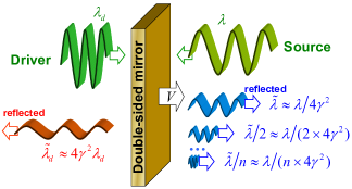
Here we discuss a novel scheme of the flying mirror, the accelerating double-sided mirror, which can efficiently reflect the counter-propagating relativistically strong electromagnetic radiation. The role of the mirror is played by a high-density plasma slab which is accelerated as a whole by an ultra-intense laser pulse (the driver) in the Radiation Pressure Dominant (RPD) regime (synonymous to the Laser Piston regime), bib:RPD . Such an acceleration can be described as the mirroring effect: it is the reflection that allows the energy transfer from the driver radiation to the co-propagating plasma slab. This effect is inverse with respect to the double Doppler effect. This plasma slab also acts as a mirror for a counter-propagating relativistically strong electromagnetic radiation (the source). As such it exhibits the properties of the sliding and oscillating mirrors, producing high harmonics. As a result, in the spectrum of the reflected radiation both the fundamental frequency of the incident radiation and all the high harmonics are multiplied by the same factor, approximately proportional to the square of the Lorentz factor of the mirror. This concept opens the way towards extremely bright sources of ultrashort energetic bursts of X-ray and gamma-ray, which become realizable with present-day technology.
In the next sections we recall some aspects of the flying mirror concept, then we present the scheme of the accelerating mirror and corresponding computer simulations. Finally, we discuss the prospects of the proposed concept.
II The frequency multiplication factor
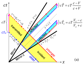
The factor by which the frequency of the reflected electromagnetic radiation is multiplied in the double Doppler effect can be derived using simple geometric arguments, as shown in Fig. 1. The one-dimensional motion of an object is represented by a world line in the plane , where is the space coordinate, is time and is the speed of light in vacuum. For an electromagnetic pulse propagating in the direction of increasing -values the world line is stright and is inclined at the angle of (clockwise) with respect to the -axis. The world line of a counter-propagating pulse is inclined at the angle of . The world line of a mirror, moving with a constant velocity, , in the direction of the -axis, is also stright, but inclined at the angle of . In principle, the mirror velocity can be equal or greater than the speed of light in vacuum, e. g., when the mirror is formed by an ionization front in plasma, bib:Ostr . In Fig. 1 (a) we show the world lines for two semi-transparent Mirrors, one propagates with velocity and another, superluminal, with velocity . We consider two consecutive electromagnetic pulses, the ”older” and the ”younger”, which interact with the mirrors. The interaction is represented by the intersection between the world lines of the pulses and Mirrors. From the intersection points, two reflected pulses are emitted. We assume that the time of the formation of reflected pulses is much less than the time period between these pulses. Under this condition, the time period, , between the reflected pulses is determined only by the time period, , between the incident pulses and the inclination angle of the world line representing the mirror.
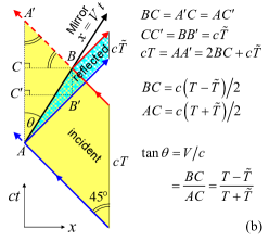
In Fig. 1 (b), the points of intersection of the older and younger pulses with the Mirror are denoted as and , respectively. From these points we draw two segments parallel to the -axis, and , where lies on the world line of the younger pulse and lies on the wold line of the reflected older pulse. The angle (between the world line of the Mirror and the -axis) is denoted as . We draw two segments parallel to the -axis, and , where and lie on . By construction, and . Since the world lines of the electromagnetic pulses form angles with respect to the -axis, the triangles and are isosceles and equal. Therefore,
| (1) |
On the other hand, it is equal to . Thus we obtain
| (2) |
Assuming that the incident pulses in Fig. 1 represent two crests of an electromagnetic wave with frequency , we obtain the reflected wave frequency, :
| (3) |
In the limit , , where
| (4) |
is the Lorentz factor of the Mirror. In the case of the superluminal Mirror-2, , the time period between the reflected pulses is given by Eq. 2 with a substitution . However, as seen in Fig. 1, the wave reflected by a superluminal mirror is reversed in time. We note that the presented derivation of the frequency multiplication factor does not use the Lorentz transformations; in principle, it is valid for any sufficiently smooth world line of the mirror provided that the act of reflection is sufficiently short at each point of the mirror’s world line.
III The reflection coefficient of thin plasma slab
Here we recall the derivation of the reflection coefficient of a moving thin plasma slab, following Refs. bib:FM ; bib:Panchenko . The plasma slab with thickness, , and density, , moves with velocity, , along the -axis, so that the density as function of and reads
| (5) |
A counter-propagating electromagnetic wave, represented by the -component of the vector potential, , is incident on the plasma slab. In the approximation of a weak electromagnetic wave, the interaction is described by the Maxwell equation:
| (6) |
where and are the electron charge and mass, is the Lorentz factor of the plasma slab.
We consider a thin slab approximation, where the slab thickness tends to zero, , while the total number of particles in the slab is constant, . Such the density is described by the Dirac delta function,
| (7) |
where we introduce a new variable (we note that has the dimension of inverse length). This approximation was used in Ref. bib:FM for calculating the reflection coefficient of the breaking wake wave, basing on the argument that in each period of the wake wave near breaking, nearly half of the electrons are concentrated in the spike of the electron density moving with the phase velocity of the wake, whereas another half are distributed almost homogeneously and moving in the opposite direction with the same velocity.
In the boosted reference frame, moving with the velocity of the plasma slab, the electromagnetic wave is interacting with an infinitely thin wall at rest. This allows us to use the analogy with the classical problem of the scattering theory (e.g., see Refs. bib:Scott and bib:FOIL ). For the boosted frame, we denote the spacial coordinate as
| (8) |
the time – as , and the frequency and wave number of the electromagnetic wave – as and . Since the magnitude of the wave 4-vector is zero in any inertial reference frame,
| (9) |
We note that for , . Representing the wave vector-potential in the dimensionless form
| (10) |
from Eq. (6) and Eq. (7) we obtain
| (11) |
where
| (12) |
is the wavelength and is the classical electron radius. Integrating Eq. (11) over in the interval , in the limit we obtain the boundary conditions for the right and left derivatives of :
| (13) |
while is continuous at . The solution to Eq. (11), describing the wave reflection, is cast in the form
| (14) |
where and are related by expressions following from the boundary condition:
| (15) | |||
| (16) |
This gives the amplitude of the reflected radiation
| (17) |
Correspondingly, the reflection coefficient defined as , is equal to
| (18) |
We note that the reflection coefficient is a Lorentz invariant, since it is expressible via transverse components of the vector-potential, which are invariant under the Lorentz transformations. For the case of normal incidence, , we obtain
| (19) |
If the plasma slab is sufficiently high, , the reflection coefficient is close to 1. In the opposite limit, , we obtain
| (20) |
where we assume . We see that the reflection coefficient is proportional to the square of the number of electrons in the slab, i. e. the reflection is coherent. In the strongly nonlinear wake wave, where and , Eq. (20) gives bib:FM . A systematic analysis of the wave-breaking regimes and caustics formation as well as the derivation of the reflection coefficients for a wide class of the plasma density singularities are presented in Ref. bib:Panchenko .
IV The accelerating mirror
A plasma slab moving with relativistic velocity can be created in the Radiation Pressure Dominant (RPD) regime of the ion acceleration (also called the Laser Piston regime), bib:RPD . In this regime an ultra-intense electromagnetic wave (driver) incident on a thin dense foil efficiently accelerates the irradiated region of the foil as a whole due to a strong radiation pressure and high reflectivity of the foil, Fig. 2. We consider the driver pulse with the electric field and length , carrying the energy . The accelerated plasma slab, co-propagating with the driver, forms a relativistic plasma mirror. For simplicity we assume that it perfectly reflects the driver pulse. The length, , of the reflected pulse is longer than that of the incident pulse by the factor , where is the Lorentz factor of the plasma mirror. The transverse electric field, , is smaller than by the same factor. Therefore, after the reflection the driver energy becomes much lower: . The mirror acquires the energy from the driver pulse. The radiation momentum is transfered to ions through the charge separation field and the ‘longitudinal’ kinetic energy of ions is much greater than that of electrons. According to Ref. bib:RPD , the ”plate” energy increases with time as , where is the number of ions with mass .
If we send a counter-propagating relativistically strong electromagnetic wave (source) onto the accelerated plasma slab, it will be (partially) reflected and the reflected wave (signal) frequency will be multiplied due to the double Doppler effect, Fig. 2. According to Eq. (3), the frequency of the reflected fundamental mode of the source increases in time as . The plasma slab acts as a double-sided mirror, which gain momentum reflecting the driver by one side and transfer momentum to the electromagnetic wave reflected by another side. The source pulse should be sufficiently weaker than the driver, nevertheless it can be relativistically strong. In the interaction with a high-intense source pulse, the accelerated plasma slab exhibits the properties of the sliding and oscillating mirrors, producing high harmonics. As a result, in the spectrum of the reflected radiation both the fundamental frequency of the incident radiation and all the high harmonics are multiplied by the same factor, approximately proportional to the square of the Lorentz factor of the mirror.
In order to investigate the feasibility of this effect we performed two-dimensional particle-in-cell (PIC) simulations using the Relativistic ElectroMagnetic Particle-mesh code REMP based on the density decomposition scheme bib:REMP . The driver laser pulse with the wavelength , the intensity W/cm, corresponding to the dimensionless amplitude , and the duration is focused with the spot size of onto a hydrogen plasma slab with the thickness and the initial electron density cm placed at . The driver is -polarized, i. e., its electric field is directed along the -axis. Its shape is Gaussian but whithout the leading part, starting from the pulse center along the -axis. At the time when the driver pulse hits the plasma slab from the left (), the source pulse arrives at another side of the slab from the right (). The source pulse is -polarized (its electric field is along the -axis). It has the same wavelength as the driver pulse. Its intensity is W/cm, corresponding to the dimensionless amplitude , its duration is and its waist size is . The source pulse has rectangular profile along the - and -axes; such the profile is not necessary for the desired effect but helps to analyse the results. We note that the -polarization of the driver may be not optimal for a smooth start of the slab acceleration in the radiation pressure dominant regime, nevertheless it was chosen in order to easily distiguish between the driver and the source pulses. In addition, our choice demonstrates the robustness of the double-surface mirror.
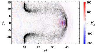
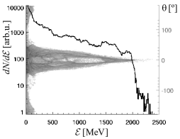
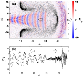

The results of the simulations are shown in Figs. 3-6, where the spatial coordinates and time units are in the laser wavelengths and wave periods, respectively. The accelerated portion of the plasma slab is seen in Fig. 3. The driver laser makes a cocoon where it is confined. At the time of 37 laser periods from the beginning of the driver-slab interaction, the ions are accelerated up to 2.4 GeV while the majority of ions in the accelerated ”plate” carry the energy about 1.5 GeV, Fig. 4. The source pulse is reflected from the accelerating plasma, as shown in Fig. 5. The frequency of the reflected radiation increases as the mirror moves faster, thus the profile of the electric field along the axis becomes more and more jagged, Fig. 5(b). In other words, the reflected pulse is chirped. In addition, as seen in Fig. 5, a portion of the source pulse reflected from the curved edges of the expanding cocoon acquires an inhomogeneous frequency upshift determined by the angle of the reflecting region. At the begining the magnitude of the reflected radiation is higher than that of the incident source (3 times higher at maximum). This is due to the frequency multiplication, specific to the double Doppler effect, and due to compression of the plasma slab under the radiation pressure of the driver pulse. Later the magnitude of the reflected radiation drops. In an instant proper frame of the accelerating ”plate”, where it is stationary for a given moment of time, the frequency of the incident source electromagnetic wave becomes higher with time, thus the plate becomes more and more transparent in accordance with Eq. (20). Correspondingly, after some time the source starts to be transmitted through the plasma more and more efficiently. This is seen in Fig. 5 where the transmitted radiation is focused because of the cocoon-like spatial distribution of the plasma.
The reflected radiation has a complex structure of the spectrum. First, it contains not only the frequency-multiplied fundamental mode of the source pulse, but also high harmonics due to the nonlinear interaction of the source with the plasma slab. This is seen in Fig. 6, showing first two consecutive cycles of the reflected radiation. Both the cycles exhibit presence of high harmonics, while the later cycle is compressed together with its harmonics in comparison with the earlier cycle. Second, the reflected radiation has a spectral shift due to the fact that the electrons affording the reflection move along the plasma slab under the action of the driver pulse. Third, the spectrum is enriched by a continuois component since the mirror moves with acceleration. The theory of this spectral structure will be presented elsewhere.
V Conclusion
In this paper we show that a solid density plasma slab, accelerated in the radiation pressure dominant regime, can efficiently reflect a counter-propagating relativistically strong laser pulse (source), thus playing a role of accelerating mirror. The reflected electromagnetic radiation consists of the reflected fundamental mode and high harmonics, all multiplied by the factor , where is the increasing velocity of the plasma slab and is the corresponding Lorentz factor. In general, the reflected radiation is chirped due to the mirror acceleartion. With a sufficiently short source pulse beeing sent with an appropriate delay to the accelerating mirror, one can obtain a high-intese ultra-short pulse of X-rays.
For the mirror velocities greater than some threshold, the distance between electrons in the plasma slab in the proper reference frame becomes longer than the incident wavelength. Thus the plasma slab will not be able to afford the reflection in a coherent manner, where the reflected radiation power is proportional to the square of the number of particles in the mirror. In this case the reflected radiation becomes linearly proportional to the number of particles. Even with this scaling one can build an ultra-high power source of short gamma-ray pulses, when the interaction of the source pulse with a solid-density plasma is in the regime of the inverse Compton scattering.
Employing the concept of the accelerating high-density mirror, one can develop a relatively compact and tunable ultra-bright high-power X-ray or gamma-ray source, which will considerably expand the range of applications of the present-day powerful sources and will create new applications and research fields. Implementation in the ”water window” will allow performing a single shot high contrast imaging of biological objects. In atomic physics and spectroscopy, it will allow performing the multi-photon ionization and producing high-Z hollow atoms. In material sciences, it will reveal novel properties of matter exposed to the high power X-rays and gamma-rays. In nuclear physics it will allow studying states of high-Z nucleus. The sources of high-power coherent X-ray and ultra-bright gamma-ray radiation also pave the way towards inducing and probing the the nonlinear quantum electrodynamics processes.
This work was partially supported by the Ministry of Education, Science, Sports and Culture of Japan, Grant-in-Aid for Creative Scientific Research No. 15002013. The authors acknowledge the support by the European Commission under contract ELI pp 212105 in the framework of the program FP7 Infrastructures-2007-1.
References
- (1) A. Einstein, Ann. Phys. (Leipzig) 17, (1905) 891.
- (2) S. V. Bulanov, et al., ”Relativistic interaction of laser pulses with plasmas,” in Reviews of Plasma Physics, edited by V. D. Shafranov (Kluwer Academic, Plenum, New York, 2001), Vol. 22, p. 227; G. A. Mourou, T. Tajima, and S. V. Bulanov, Rev. Mod. Phys. 78, (2006) 309.
- (3) K. Landecker, Phys. Rev. 86, (1952) 852.
- (4) L. A. Ostrovskii, Soviet Physics Uspekhi 116, (1976) 315.
- (5) F. R. Arutyunian and V. A. Tumanian, Phys. Lett. 4, (1963) 176; Y. Li, et. al., Phys. Rev. ST Accel. Beams 5, (2002) 044701.
- (6) V. I. Semenova, Sov. Radiophys. Quantum Electron. 10, (1967) 599; W. B. Mori, Phys. Rev. A 44, (1991) 5118; R. L. Savage, Jr., et al., Phys. Rev. Lett. 68, (1992) 946.
- (7) A. S. Pirozhkov, et al., Phys. Lett. A 349, (2006) 256; Phys. Plasmas 13, (2006) 013107.
- (8) S. V. Bulanov, et al., Phys. Plasmas 1, (1994) 745; D. von der Linde, et al., Phys. Rev. A 52, (1995) R25. M. Zepf, et al., Phys. Rev. Lett. 98, (2007) 103902.
- (9) V. A. Vshivkov, et al., Phys. Plasmas 5, (1998) 2727.
- (10) S. V. Bulanov, T. Zh. Esirkepov, and T. Tajima, Phys. Rev. Lett. 91, (2003) 085001.
- (11) L. Plaja, et al., J. Opt. Soc. Am. B 15, (1998) 1904; N. M. Naumova, et al., Phys. Rev. Lett. 92, (2004) 063902.
- (12) S. V. Bulanov and A. S. Sakharov, Pis’ma Zh. Eksp. Teor. Fiz. 54, (1991) 208 [JETP Lett. 54, (1991) 203]; S. V. Bulanov, et al., Phys. Rev. Lett. 74, (1995) 710; N. H. Matlis, et al., Nature Phys. 2, (2006) 749.
- (13) A. V. Panchenko, et al., Phys. Rev. E 78, (2008) 056402.
- (14) T. Esirkepov, et al., Phys. Rev. Lett. 92, (2004) 175003; S. V. Bulanov, et al., Plasma Phys. Rep. 30, (2004) 221; F. Pegoraro and S. V. Bulanov, Phys. Rev. Lett. 99, (2007) 065002.
- (15) A. Scott, Nonlinear Science. Emergence and Dynamics of Coherent Structures 2nd Eddition. (Oxford Univ. Press, Oxford, 2003).
- (16) T.Zh.Esirkepov, Comput. Phys. Comm. 135, 144 (2001).