Enhanced Domain Wall Motion in the Spin Valve Nanowires
Abstract
According to the recent experiment by the Fert group, the velocity of domain wall motion in the spin valve ferromagnetic nanowires was almost doubly enhanced compared to the old value. In this work, we propose an additional torque model, arising from the interlayer exchange interaction, which can enhance or suppress the domain wall velocity depending on the sign of the exchange constant or the wall motion direction relative to the magnetization orientation of the fixed layer.
pacs:
75.45.+j, 75.25.-b, 85.75.-dThe dynamics of magnetic domain wall (DW) in the ferromagnetic nanowires has been a very active research area DW_motion in spintronics. The DW motion under the magnetic field seems to be well documented experimentally and understood theoretically in terms of the phenomenological Landau-Lifshitz-Gilbert (LLG) equation. After the Berger’s pioneering work Berger1984 about the spin transfer torque, many experimental groups exp_DW1 ; exp_DW2 ; exp_DW3 ; exp_DW4 ; exp_DW5 ; exp_DW6 observed the magnetic DW motion under spin current and much theoretical efforts bazaliy ; tatara ; barnes ; li_zhang ; thiaville have been exerted to refine the spin torque theory. Though several theoretical issues are still unresolved, the experimental efforts are continued in order to enhance the DW velocity Parkin100 ; Fert180 and reduce the critical current density. exp_DW3 These two factors are essential for the device applications in logic DW_logic as well as in memory. DW_memory
Recently, a highly enhanced DW velocity under spin current was reported Fert180 in the spin valve ferromagnetic nanowires. The spin valve nanowire consists of FeNi/Cu/Co/CoO layers. The Co layer is magnetized along the magnetic easy axis or the wire direction and its magnetization is uniform and fixed by exchange bias. The magnetization in the NiFe layer is also directed into the wire direction and the DW is introduced. The current flow in plane induces the DW motion. While the highest DW velocity reported Parkin100 till now was about 100 m/s in a ferromagnetic nanowire with one layer, the observed DW velocity in the spin valve (with trilayer) Fert180 reached up to 180 m/s. The spin valve nanowires seem to be very promising for the future device applications.
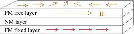
In this paper we would like to propose another source of spin torque in the spin valve nanowires (Fig. 1) which can enhance or suppress the DW velocity under spin current. The two top (free) and bottom (fixed) layers are separated by the nonmagnetic spacer layer. In the magnetic multilayers, it is well known that there exists the interlayer exchange coupling. Ever since the first observation Grunberg1986 of an antiferromagnetic coupling between two magnetic layers in the transition metal multilayers, the interlayer exchange couplings as a function of the interlayer spacing have been observed osc_ilc to be oscillating between ferromagnetic and antiferromagnetic couplings. This interlayer exchange coupling is a source of an additional torque in the spin valve nanowires. Though the theory of current-induced domain wall motion (CIDWM) is still very controversial, we adopt the generalized LLG equation under spin current in order to illustrate the enhanced or suppressed domain wall motion based on our model.
The phenomenological LLG (Landau-Lifshitz-Gilbert) equation has been very useful in understanding the dynamics of magnetic domain walls under the magnetic field. This LLG equation was also used for studying the CIDWM by adding the spin transfer torque. In general, the LLG equation for magnetization is given by
| (1) |
Here is the unit vector for magnetization of the free layer and is the effective magnetic field (applied, exchange, and anisotropy fields). The first term describes the precessional motion of under , the second term is the Gilbert damping torque ( is the dimensionless damping constant), and is any additional torque acting on . Depending on the current flow direction, current in plane (CIP) or current perpendicular to plane (CPP), two models are proposed
| (2) | |||||
| (3) |
In the CIP geometry, the first (second) term is (non)adiabatic torque and is proportional to the current density and the spin polarization. In the CPP geometry, is the gyromagnetic ratio and both and are proportional to the current and the spin polarization, is the magnetization unit vector in the fixed layer. The effect of on the DW motion in spin valve nanowires was studied spinvalve_CPP recently theoretically. However. in the experiment Fert180 of the spin valve, the DW motion was measured in the CIP geometry, but not in the CPP geometry. In this work, we study the LLG equation under the action of and the interlayer exchange coupling. The interlayer exchange coupling is modeled by the following Hamiltonian interlayer
| (4) |
For the positive (negative) exchange constant , the coupling is ferromagnetic (antiferromagnetic). The sign of exchange coupling depends on the spacing of the nonmagnetic layer sandwiched in between two ferromagnetic layers. The above interlayer coupling gives rise to an additional torque on the magnetization .
| (5) |
This torque is nonzero only near the domain wall and vanishes in the collinear sections of a nanowire. This torque is very similar to the second term in , but there is a big difference: is nonzero even when there is no current perpendicular to the spin valve, while without any perpendicular current.
Our goal is to study the domain wall motion under the action of two torques and .
| (6) |
The effective magnetic field is computed from the following magnetic energy density for magnetization
| (7) |
Here is the exchange coupling, and are the anisotropy constants, and is the lattice spacing. Representing the magnetization in terms of two Euler angles and and minimizing the magnetic energy, a transverse wall is obtained.
| (8) | |||||
| (9) |
Here is the DW position and defines the domain wall width.
| (10) |
In order to see the effect of the interlayer exchange interaction, we consider the above rigid transverse domain wall. Though the azimuthal angle depends on time, the time dependence of the domain wall width can be neglected in the leading approximation. Finally the LLG equation in components is
| (11) | |||||
| (12) |
In the steady mode, so that the domain wall velocity is given by
| (13) |
The first term in comes from the spin transfer torque from spin current, while the second term from the interlayer exchange coupling.
In the spin valve structure of a ferromagnetic nanowire, the domain wall motion is affected by the fixed layer via the interlayer exchange interaction. the DW velocity can be either enhanced or suppressed depending on the relative direction of DW motion and the magnetization orientation of the fixed layer or the sign of the interlayer exchange constant. For the ferromagnetic coupling, footnote the DW velocity is enhanced (suppressed) when its motion is directed along (against) the magnetization orientation of the fixed layer. For the antiferromagnetic coupling, the DW velocity behaves in an opposite way compared to the ferromagnetic coupling case.
Our result shows that the domain wall keeps moving even in the absence of driving current. This is obvious because two magnetizations tend to be (anti)aligned for (anti)ferromagnetic coupling. In real samples, the pinning potentials will tend to block the domain wall motion induced by the interlayer exchange. The presence of the interlayer coupling will help enhance the DW motion above the critical current after overcoming the pinning potentials, if the condition is right. In the experiment, Fert180 only one-way motion of DW (probably along the magnetization of Co layer) under spin current is reported. According to the interlayer exchange coupling, the wrong way motion of DW will be suppressed by the interlayer torque. This will be a critical test of the interlayer exchange torque in the spin valve system.
Our model study can be equally applied to the ferromagnetic nanowire with the magnetic tunnel junction structure. Slonczewski mtj predicted the exchange interaction between two ferromagnetic layers which are separated by the insulating barrier, even in the absence of the perpendicular current flow. Since the effect of the interlayer exchange coupling gets larger with larger couplings, the thinner insulating barrier will be more favorable. Another strong point of the MTJ spin valves will be a weaker dependence of the interlayer exchange coupling on the current in plane. In the case of nonmagnetic metallic spacer, the electric current may well generate the electron-hole excitations and disrupt the spin coherence so that the interlayer exchange coupling is reduced just like the thermal excitation. At least, this disruption is absent for the insulating spacer.
References
- (1) See, for example, recent review articles in the special issue (current perspectives on spin transfer torques) of J. Magn. Magn. Mater. 320, pp 1190 - 1311 (2008).
- (2) L. Berger, J. Appl. Phys. 55, 1954 (1984).
- (3) A. Yamaguchi, T. Ono, S. Nasu, K. Miyake, K. Mibu, and T. Shinjo, Phys. Rev. Lett. 92, 077205 (2004).
- (4) N. Vernier, D. A. Allwood, D. Atkinson, M. D. Cooke, and R. P. Cowburn, Europhys. Lett. 65, 526 (2004).
- (5) M. Yamanouchi, D. Chiba, F. Matsukura, and H. Ohno, Nature 428, 539 (2004); M. Yamanouchi, D. Chiba, F. Matsukura, T. Dietl, H. Ohno, Phys. Rev. Lett. 96, 096601 (2006).
- (6) M. Kläui, C. A. F. Vaz,J. A. C. Bland, W. Wernsdorfer, G. Faini, E. Cambril, L. J. Heyderman, F. Nolting, U. Rudiger, Phys. Rev. Lett. 94, 106601 (2005).
- (7) G. S. D. Beach, C. Knutson, C. Nistor, M. Tsoi, J. L. Erskine, Phys. Rev. Lett. 97, 057203 (2006).
- (8) M. Hayashi, L. Thomas, Ya. B. Bazaliy, C. Rettner, R. Moriya, X. Jiang, and S. S. P. Parkin, Phys. Rev. Lett. 96, 197207 (2006).
- (9) M. Hayashi, L. Thomas, C. Rettner, R. Moriya, Y. B. Bazaliy, and S. S. P. Parkin, Phys. Rev. Lett. 98, 037204 (2007).
- (10) S. Pizzini, V. Uhlir, N. Rougemaille, E. Bonet, M. Bonfim, J. Vogel, S. Laribi, V. Cros, R. Mattana, C. Deranlot, F. Petroff, A. Fert, E. Jimenez, J. Camarero, C. Ulysse, G. Faini, and C. Tieg, cond-mat/0810.3576 (2008).
- (11) Y. B. Bazaliy, B. A. Jones, and S.-C. Zhang, Phys. Rev. B 57, R3213 (1998).
- (12) G. Tatara and H. Kohno, Phys. Rev. Lett. 92, 086601 (2004); J. Shibata, G. Tatara, and H. Kohno, ibid 94, 076601 (2005).
- (13) Z. Li and S. Zhang, Phys. Rev. Lett. 92, 207203 (2004); S. Zhang and Z. Li, ibid 93, 127204 (2004).
- (14) S. E. Barnes and S. Maekawa, Phys. Rev. Lett. 95, 107204 (2005).
- (15) A. Thiaville, Y. Nakatani, J. Miltat, and Y. Suzuki, Europhys. Lett. 69, 990 (2005).
- (16) D. A. Allwood, G. Xiong, C. C. Faulkner, D. Atkinson, D. Petit, and R. P. Cowburn, Science 309, 1688 (2005).
- (17) S. S. P. Parkin, M. Hayashi, and L. Thomas, Science 320, 190 (2008).
- (18) P. Grünberg, R. Schreiber, Y. Pang, M. B. Brodsky, and H. Sowers, Phys. Rev. Lett. 57, 2442 (1986).
- (19) S. S. P. Parkin, Phys. Rev. Lett. 67, 3598 (1991).
- (20) A. V. Khvalkovskiy, K. A. Zvezdin, Ya. V. Gorbunov, A. K. Zvezdin, V. Cros, and J. Grollier, cond-mat/0806.2369 (2008).
- (21) See, for example, a review article: M. D. Stiles, J. Magn. Magn. Mater. 200, 322 (1999).
- (22) In the text, the head-to-head DW is considered. For the tail-to-tail DW, the opposite results are obtained compared to the head-to-head DW.
- (23) J. C. Slonczewski, Phys. Rev. B 39, 6995 (1989).