Broadband cloaking with volumetric structures composed of two-dimensional transmission-line networks
Abstract
The cloaking performance of two microwave cloaks, both based on the recently proposed transmission-line approach, are studied using commercial full-wave simulation software. The cloaks are shown to be able to reduce the total scattering cross sections of metallic objects of some restricted shapes and sizes. One of the studied cloaks is electrically small in diameter, and the other is electrically large, with the diameter equal to several wavelengths.
Keywords: Transmission-line network; scattering cross section; electromagnetic cloak.
PACS 41.20.Jb, 84.40.Xb
I Introduction
Cloaking, i.e., the reduction of an object’s total scattering cross section for arbitrary incidence directions, has recently gained wide interest in the literature, see the review paper by Al et al. Alu_review for a representative list of references and explanations of the main cloaking principles. There exists several different approaches to cloaking, such as the coordinate-transformation approach Leonhardt ; Pendry ; Schurig and the so-called plasmonic cloaking Alu_review ; Alu .
In addition to the aforementioned cloaking techniques, an alternative aproach has been proposed recently Alitalo_cloak_TAP . This approach is based on the use of transmission-line networks that are coupled with the surrounding medium, and it has been studied in our recent papers Alitalo_cloak_TAP ; Alitalo_cloak_iWAT08 ; Alitalo_cloak_URSI08 ; Alitalo_cloak_META . In this paper we study two cloaks that are based on the designs presented in Alitalo_cloak_iWAT08 ; Alitalo_cloak_URSI08 and analyse their cloaking performance in free space. Both studied cloaks are cylindrically shaped and consist of periodically stacked two-dimensional networks of transmission lines. One of the cloaks is electrically small, with the diameter of the cloaked region about one fourth of the wavelength. The other cloak is electrically large, with the diameter of the cloaked region being approximately four wavelengths. Both cloaks are studied under free space conditions with TE-polarized plane wave illumination.
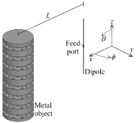
To get more insight on the applicability of these types of cloaks in realistic antenna applications (ideal plane-wave illumination is not a good approximation for many practical situations), we apply the designed electrically small cloak in a situation where a metallic object is placed near a radiating dipole antenna, thus affecting the radiation pattern of the antenna.
II Electrically large cloak
The electrically large cloak is similar to the one recently presented in Alitalo_cloak_URSI08 . We use a two-dimensional transmission-line network with the shape as illustrated in Fig. 1. The transmission lines are composed of parallel metal strips and the coupling between the network and the free space surrounding the network is achieved by using a “transition layer.” This layer is formed by gradually enlarging the transmission line strips to cover the whole interface between the network and free space Alitalo_cloak_TAP . In this case the two-dimensional network lies in the -plane, and the cloak structure can be made volumetric by stacking these networks on top of each other along the -direction Alitalo_cloak_TAP ; Alitalo_cloak_iWAT08 ; Alitalo_cloak_URSI08 ; Alitalo_cloak_META .

The objects that can be cloaked with this set of networks include two-dimensional arrays or three-dimensional meshes of metal or any other material. Any type of object that can fit in the space that is inside the cloak but outside the sections of transmission lines, can be cloaked with this approach. The cloaking effect is naturally best for cloaking of metallic objects since alone these objects scatter significantly.
The cloaking efficiency of the electrically large cloak of Fig. 1 is studied using a commercial full-wave simulation software Ansoft HFSS Ansoft . To simplify the simulations, we consider the cloak structure to be infinitely high, i.e., there is an infinite number of the two-dimensional cloaks stacked on top of each other creating a volumetric structure. The period of the two-dimensional transmission-line networks, from which the volumetric cloak is constructed from, is 8 mm. We can hence assume that the networks have isotropic propagation properties at least up to the frequency of 3 GHz Alitalo_cloak_TAP .
To improve the cloaking efficiency of the previously studied structure Alitalo_cloak_URSI08 at the design frequency of 3 GHz, the width of the parallel strip transmission lines is tuned from 1.38 mm Alitalo_cloak_URSI08 to 1.34 mm with the separation (i.e., height) of the transmission lines being 2 mm in the -direction. This tuning can be considered as tuning of the characteristic impedance of the network itself, as explained in Alitalo_cloak_TAP . With this tuning the transmission-line networks are matched better to the free-space impedance and thus the cloaking effect is improved. The transmission lines of the transition layer have equal width and height and the length of these lines is equal to 40 mm, see Fig. 1. At the interface between the network and free space, the width and height of the transmission lines of this transition layer are equal to 7.73 mm. This value is determined simply by the circumference of the cloak structure at this interface and by the number of transmission lines in the transition layer (circumference divided by the number of transmission lines).
The transmission-line strips are modelled in the simulation software as infinitely thin sheets of perfectly conducting material (PEC). As a reference object we use the object that we want to cloak, which in this case is a two-dimensional array consisting of infinitely long PEC rods with a square cross section of 4 mm 4 mm. The array lies in the -plane, i.e., the rods are directed along the -axis. This array has a cylindrical shape so that it fills the available space inside the cloak network almost entirely and it has the same period as the network, i.e., mm. There are 51 PEC rods along the diameter of this cylindrical array, which means that the cloaked object’s electrical size is approximately at 3 GHz.
The cloak operation is studied by simulating the scattering cross sections (SCS) of the reference object with and without the cloak to all directions in the -plane. The SCS is simulated by illuminating the simulation models with TE-polarized plane waves (electric field parallel to the -axis) and then calculating the scattered power in the far field. By integrating the SCS over the angle which lies in the -plane, we obtain the total SCS of the two cases. To give a simple representation of the results, we normalize the total SCS of the cloaked object to the total SCS of the uncloaked object. Thus, the resulting normalized total SCS () is smaller than 1 when reduction of the total scattering cross section is achieved.
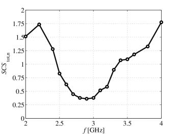
In Fig. 2 versus the frequency is shown for the electrically large cloak. is smaller than 1 in a relative bandwidth of approximately 15 percent, with the center frequency at 2.9 GHz. The minimum value of is obtained at the frequency of 2.9 GHz, where , i.e., the total scattering cross section of the reference object is reduced by approximately 64 percent. At frequencies below approximately 2.5 GHz and above 3.3 GHz, the phase velocity mismatch between the cloak and the free space causes an increase in the cloak’s scattering even above the level of the bare reference object, as expected Alitalo_cloak_TAP .
III Electrically small cloak
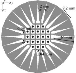
The electrically small cloak studied here is a modification of a similar cloak presented in Alitalo_cloak_iWAT08 . Here we tune the operation frequency of the cloak from 2 GHz Alitalo_cloak_iWAT08 to 3 GHz, which was the operation frequency also in the previous example. This can be done simply by keeping the cloak structure the same as in Alitalo_cloak_iWAT08 but just decreasing the period of the transmission-line networks to obtain the same electrical size (diameter) of the cloak at a higher frequency. The dimensions of the transmission lines are also tuned accordingly to obtain optimal impedance matching at a higher frequency. This tuning is done with full-wave simulation software Ansoft , by changing the width of the strips gradually and analyzing the total scattering cross section. The resulting cloak structure, with the period of the network reduced from 8 mm to 5 mm and the length of the transmission lines in the transition layer reduced from 40 mm to 20 mm, is shown in Fig. 3. The resulting network has a diameter of mm, while the diameter of the cloaked object is mm, i.e., at 3 GHz.
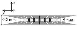
Again, as in the case of the electrically large cloak, the dimensions of the transition layer depend on the circumference of the transition layer and the number of transmission lines in this layer, now resulting in the width and height of 9.2 mm at the interface with free space. The transmission lines composing the network itself are again realized as parallel metal strips (modelled by infinitely thin PEC strips in the simulation software), with the width and height equal to 1.04 mm and 1.5 mm, respectively. The reference object in this case is a two-dimensional array of infinitely long PEC rods, now having a circular cross section with the diameter of 2 mm, see Fig. 3.
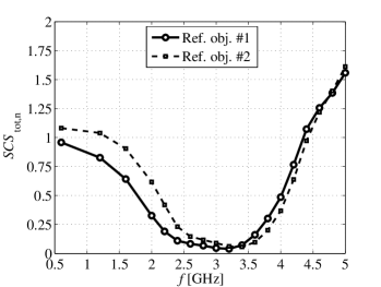
The scattering simulations are conducted as described in the previous section, i.e., a TE-polarized plane wave travelling in the -direction illuminates the structures which are modelled as infinitely periodic in the -direction. The resulting versus the frequency is plotted in Fig. 4 (solid line), showing the relative cloaking bandwidth of approximately 158 percent, with the center frequency being at 2.425 GHz. The best cloaking performance with is obtained at the frequency of 3.2 GHz. Therefore, at this frequency the total scattering cross section of the reference object is reduced by 96 percent.
The isotropy of the cloak in the -plane is confirmed by conducting the same scattering simulations as above for different incidence angles in the -plane. Due to the symmetry of the cloak, it is enough to study incidence angles between and . We carried out the scattering simulations between these incidence angles, with the step of , at the frequency of 3.2 GHz. The resulting varied approximately between the values of 0.03 and 0.045.
IV Cloaking an object near a dipole antenna
Plane-wave illumination is not a good approximation in many realistic situations where cloaking would be beneficial. Especially in antenna applications this will most probably be an important issue. To demonstrate the robustness of our cloaking approach with respect to this problem, we simulate a finite-sized cloak near a dipole antenna. The cloak is used to “hide” a metallic object that blocks the antenna’s radiation in certain directions. See Fig. 5 for the illustration of the problem. The metallic object is such that we can use the electrically small cloak, studied in the previous section, to cloak it. Instead of a two-dimensional array of PEC rods we choose to cloak a more realistic structure, that could be used as a support strut, etc. In order to make the PEC rods of the reference object connected to each other, we introduce PEC discs of a finite height periodically connected to the array of PEC rods (same as in Fig. 3), as illustrated in Fig. 5.

First, to study the effect of changing the reference object, we repeat the scattering simulations done in the previous section for this new reference object (modelled as an infinitely high structure, due to the periodicity of the simulation model discussed in the previous section). The results are shown in Fig. 4 (dashed line), demonstrating that the cloaking effect remains the same, just a slight shift in the frequency of the optimal cloaking performance is observable.
Two different cases of the problem presented in Fig. 5 are studied: the distance between the dipole and the metallic object being mm and mm. This is to study the operation of the cloak in the near-field region of the antenna (note that the wavelength at 3 GHz is equal to 100 mm). Also, moving the object closer to or further from the antenna changes the incidence angle of the fields that impinge on the cloak in both - and -planes. One purpose of these simulations is to study how sensitive the cloak is to changes in the incidence angle .
To cloak this metal object, we have used the electrically small cloak studied in the previous section, but in this case the cloak has a finite height with eight periods of the cloak in the -direction. As can be seen from Fig. 5, the metal object requires placement of eight two-dimensional transmission-line networks one upon another in order to cover the whole object in the -direction. The height of the metal object is mm mm. The transmission-line networks of the cloak structure run in the space between the PEC discs, where there are only the vertical PEC rods, similar to Fig. 3.
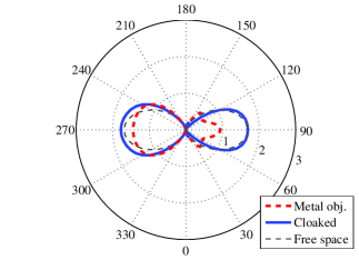
Three different scenarios were simulated for both values of : 1) dipole alone in free space, 2) dipole with the metallic object at distance away from the dipole, and 3) dipole with the cloaked metal object. The easiest way to analyse the results is to study the radiation patterns in the - and -planes and compare the different scenarios with each other. We have run simulations studying several frequencies, and for both values of the best directivity patterns are obtained at 3.1 GHz. The goal here is to have as good agreement with the free space scenario and the cloaked scenario as possible, in the forward and backward directions (, and , ). See Fig. 6 for the results for the case of mm, which demonstrates that the metal object alone is causing massive deformation of the radiation pattern. When the object is “cloaked,” the directivity pattern resembles the free space situation much better, both in - and -planes.

For the case of mm, see Fig. 7. In this case the cloak cannot preserve the ideal directivity pattern as well as in the previous case. This is expected since the cloak is now in the near-field region of the dipole. Still, for both -plane and -plane patterns the radiation in the direction of the object (, ) is almost ideal, whereas with the metal object alone, the radiated power in this direction is strongly mitigated.


V Conclusions
We have studied two electromagnetic cloaks, both composed of layered two-dimensional transmission-line networks. The cloaking performance is studied using a commercial full-wave simulation software. The performance of both cloaks is first evaluated for ideal plane-wave illumination. The other cloak, which is electrically smaller and exhibits larger bandwidth, is simulated also in an antenna scenario, where a metal object blocking the antenna radiation is cloaked.
Acknowledgements
This work has been partially funded by the Academy of Finland and TEKES through the Center-of-Excellence program and partially by the European Space Agency (ESA–ESTEC) contract no. 21261/07/NL/CB (Ariadna program). P. Alitalo acknowledges financial support by the Finnish Graduate School in Electronics, Telecommunications, and Automation (GETA), the Emil Aaltonen Foundation, and the Nokia Foundation.
References
- (1) A. Al and N. Engheta, “Plasmonic and metamaterial cloaking: physical mechanisms and potentials,” Journal of Optics A: Pure and Applied Optics, vol. 10, 093002, 2008.
- (2) U. Leonhardt, “Optical conformal mapping,” Science, vol. 312, pp. 1777–1780, 2006.
- (3) J.B. Pendry, D. Schurig, and D.R. Smith, “Controlling electromagnetic fields,” Science, vol. 312, pp. 1780–1782, 2006.
- (4) D. Schurig, J.J. Mock, B. J. Justice, S.A. Cummer, J.B. Pendry, A.F. Starr, and D.R. Smith, “Metamaterial electromagnetic cloak at microwave frequencies,” Science, vol. 314, pp. 977–980, 2006.
- (5) A. Al and N. Engheta, “Achieving transparency with plasmonic and metamaterial coatings,” Phys. Rev. E, vol. 72, 016623, 2005.
- (6) P. Alitalo, O. Luukkonen, L. Jylhä, J. Venermo, and S. A. Tretyakov, “Transmission-line networks cloaking objects from electromagnetic fields,” IEEE Trans. Antennas Propagat. vol. 56, pp. 416–424, 2008.
- (7) P. Alitalo and S. Tretyakov, “Cylindrical transmission-line cloak for microwave frequencies,” Proc. 2008 IEEE International Workshop on Antenna Technology, 4-6 March 2008, Chiba, Japan, pp. 147–150.
- (8) P. Alitalo and S. Tretyakov, “On electromagnetic cloaking – general principles, problems and recent advances using the transmission-line approach,” Proc. 2008 URSI General Assembly, 7-16 August 2008, Chicago, USA, p. B01p9 (invited).
- (9) P. Alitalo, S. Ranvier, J. Vehmas, and S. Tretyakov, “A microwave transmission-line network guiding electromagnetic fields through a dense array of metallic objects,” Metamaterials, in press. Preprint http://arxiv.org/abs/0805.4055.
- (10) The homepage of Ansoft corporation, http://www.ansoft.com/.