Space-charge mechanism of aging in ferroelectrics: an exactly solvable two-dimensional model
Abstract
A mechanism of point defect migration triggered by local depolarization fields is shown to explain some still inexplicable features of aging in acceptor doped ferroelectrics. A drift-diffusion model of the coupled charged defect transport and electrostatic field relaxation within a two-dimensional domain configuration is treated numerically and analytically. Numerical results are given for the emerging internal bias field of about which levels off at dopant concentrations well below ; the fact, long ago known experimentally but still not explained. For higher defect concentrations a closed solution of the model equations in the drift approximation as well as an explicit formula for the internal bias field is derived revealing the plausible time, temperature and concentration dependencies of aging. The results are compared to those due to the mechanism of orientational reordering of defect dipoles.
pacs:
77.80.Dj,77.80.Fm,77.84.Dy,61.72.jdI Introduction
The phenomenon of gradual change of physical properties with time, called aging, is for a long time known feature of ferroelectrics, especially when acceptor doped plessner56aging ; ikegami67mechanism ; takahashi70space ; thomann72stabilization ; carl78electrical ; takahashi82 ; arlt88internal ; Lohkamper1990Gauss ; Warren1995chargetrapping ; Afanasjev2001 ; zhang05insitu ; zhang06aging ; Morozov2008 . Aging reveals itself in quasi-logarithmic decrease of the dielectric constant with time plessner56aging ; thomann72stabilization , reduction of domain wall mobility leading to stabilization in the aged domain structure ikegami67mechanism , altered shape of polarization loops in both poled and unpoled aged samples takahashi70space ; carl78electrical ; takahashi82 ; Afanasjev2001 ; zhang05insitu ; zhang06aging ; Morozov2008 and related indications. A characteristic aging time, , a clamping pressure on the domain walls, , and an internal bias field, , were introduced as parameters quantifying aging carl78electrical ; takahashi82 .
In past three decades several concepts were developed TagantsevReview ; dawber05physics to explain the aging phenomena in terms of domain splitting ikegami67mechanism , space charge formation takahashi70space ; thomann72stabilization , electronic charge trapping at domain boundaries Warren1995chargetrapping ; Afanasjev2001 , ionic drift hage80_02 ; lamb86_02 ; scott87activation ; Morozov2008 or reorientation of defect dipoles arlt88internal ; Lohkamper1990Gauss ; zhang05insitu ; zhang06aging . The latter concept based on the widely recognized mechanism of gradual orientation of defect dipoles formed by the charged acceptor defects and oxygen vacancies has suggested probably most successful quantitative explanation of many features relevant to aging and fatigue in ferroelectrics, particularly, plausible time and temperature dependencies of . Nevertheless, some long standing questions remain open, most pronounced among them the dependence of and on the defect concentration carl78electrical ; takahashi82 . Resulting from the individual cage motion of an oxygen vacancy around an acceptor defect insensitive to presence of other defect dipoles in the dipole reorientation model arlt88internal ; Lohkamper1990Gauss is expected to be independent on the acceptor concentration. Similarly, independent contributions of different defect dipoles to the clamping pressure in this model have to result in directly proportional to the concentration. However, the experimentally observed saturation of at medium concentrations as well as distinct concentration dependence of carl78electrical ; takahashi82 ; arlt88internal provides indications of some collective mechanism of aging.
In this paper, therefore, we prove an alternative, space charge mechanism to explain the above mentioned features of aging. It may also be related to the self-polarization phenomenon and internal field-induced, migratory polarization observed in thin ferroelectric films Afanasjev2001 ; Kholkin1998 . Recently, a model quantifying the space charge mechanism was advanced lupascu06aging ; Genenko-ferro2007 ; Genenko-ferro2008 which shows that the clamping pressure and the field comparable with experiments can result from the formation of space charge zones near charged domain boundaries assuming small but finite mobility of charged defects. Aging was studied first for low defect concentrations about lupascu06aging ; Genenko-ferro2007 , and the effect of anisotropy was considered Genenko-ferro2008 . Here we apply the isotropic, two-dimensional version of this model Genenko-ferro2007 to study aging of unpoled ferroelectrics for a wide range of acceptor concentrations and present numerical and analytical results on temperature, concentration and time dependencies of . Gradual change of material properties under the effect of the external dc or ac electric field, e.g. fatigue phenomenon, is not considered at this stage.
II Model of a ferroelectric grain
Main assumptions of the model Genenko-ferro2007 used here are: (a) availability of mobile charged defects in amount sufficient to substantially compensate the bound charge at the domain boundaries and (b) presence of strong local depolarization fields in the unpoled ferroelectric material.
Let us consider the assumption (a). The conductivity of perovskites has been extensively studied during the past two decades Choi1986BTOChemistry ; waser91bulk ; Brennan1995 ; Raymond1996perovskitechemistry ; DMSmyth2003 ; Guo2005conductivity ; Ohly2006 . It was established that, depending on temperature and partial pressure of oxygen, perovskites may exhibit ionic or electronic conductivity, so that the n-type conductivity prevails under reducing conditions and the p-type in oxidizing atmospheres Choi1986BTOChemistry ; Raymond1996perovskitechemistry ; DMSmyth2003 . The ionic conductivity prevails between the above two areas of electronic conductivity and is clearly dominated by oxygen vacancies. It was shown also that the bulk mobilities of electrons and holes are not activated in and exceed the activated mobility of vacancies by many orders of the magnitude. Nevertheless, at atmospheric partial oxygen pressure and not very high temperatures, the concentration of electronic carriers remains less than the concentration of vacancies by many orders of the magnitude and is by far not sufficient to compensate the polarization bound charge. Moreover, the bulk concentration of electronic carriers is so small that the corresponding Debye screening length strongly exceeds the typical grain size. This allows one to entirely neglect electronic screening of the local bound charges. The same applies also to ambient electronic carriers in the intergranular space though their concentration may exceed the bulk one by few orders of the magnitude Guo2005conductivity . The balance between the electronic and ionic species may be substantially changed locally right near the charged domain boundaries because of the electronic band bending by very strong local depolarization fields; however, this possibility depends on the reduction potentials of certain metal dopants Gallardo2008 . In our study we suppose for simplicity that concentration of electronic carriers is negligible in and outside the ferroelectric grains. The oxygen vacancy concentration is usually fixed by acceptor defects even in the nominally undoped materials, since these are as a rule unintentionally acceptor doped Raymond1996perovskitechemistry ; DMSmyth2003 ; Guo2005conductivity . For these reasons, we will assume in the following that only oxygen vacancies participate in charge migration.
Consider now the assumption (b). In the perfectly ordered domain system the bound charges at the domain boundaries can be fully compensated resulting in complete suppression of the depolarization fields inside the bulk ferroelectric. Experimental studies show that it is not the case in real, disordered systems. Considering the high resolution images of domain patterns in and lead zirconate titanate (PZT) samples by scanning transmission electron microscopy Gregg2006 , by bright field transmission electron microscopy SchmittTEM2007 and by secondary electron spectroscopy FarooqSEM2008 one can observe numerous places where the uncompensated bound charges should emerge and, consequently, local depolarization fields can be present. Three relevant circumstances can be identified, namely, when a domain array a) ends up in an unpolarized area inside the grain, b) meets a domain wall of another domain array instead of charged domain faces, c) ends up at the grain boundary contacting the wide enough unpolarized integranular area. To investigate quantitatively the consequencies of the presence of uncompensated bound charges in the material the third of the above mentioned cases, (c), will be representatively studied in the following. Since the depolarization field of a domain array decays exponentially at the distance equal to the domain width lupascu06aging ; Genenko-ferro2007 , it suffices to assume the intergrain spacing larger than to get the neighbour grains electrically independent. That is why, for studying the effects of local depolarization fields, a model of a single ferroelectric grain surrounded by unpolarized medium may be chosen.
Let us start with a quadratic ferroelectric grain of zero total polarization surrounded by an infinite dielectric medium. We imagine a two-dimensional periodic array of domains in the grain cut by the interfaces with dielectric, and , perpendicular to the direction of spontaneous polarization which is along the -direction of a Cartesian coordinate system (Fig. 1).
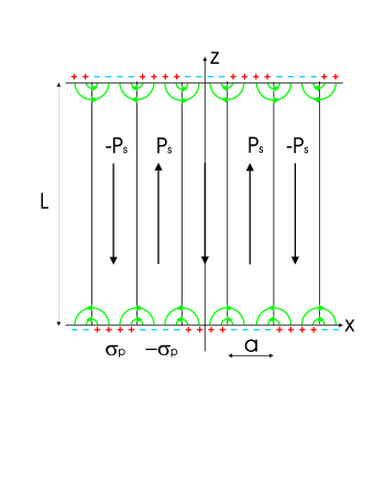
The system is supposed to be uniform in the -direction so that no variable is -dependent. If the length of the domains along the -axis is much larger than their width along the -axis, which is typically the case in experiments, electric field lines are effectively closed at the same side of the grain. Finite-element simulations of the electric field in the finite domain array shows a virtually periodic field pattern along the axis everywhere but the very ends of the array lupascu06aging ; Genenko-ferro2008 . That is why we can consider a periodic domain array infinite along the axis as a representative model for a finite multi-domain grain. This model configuration is well-known in the physics of polarized media and was used for the study of equilibrium and dynamic properties of ferromagnetic Kittel1946 ; LandauElectrodynamicsContinuum and ferroelectric Mitsui1953 materials.
Furthermore, since both components of the depolarization field exponentially decrease towards the interior of the grain along the -axis lupascu06aging ; Genenko-ferro2007 , transport of the charged defects driven by the field is expected to occur in the vicinity of the grain boundaries and . Considering charge migration near the interface we can therefore assume the domains to be infinite along the -axis without introducing a substantial error. Apparently, the same process of charge separation occurs at the other grain boundary, , too. Calculating the forces exerted upon the domain walls, both ends of the domains must be taken into account.
Hence, to study the depolarization field induced charge migration it is sufficient to consider the interface between the domain array occupying the ferroelectric half space and the dielectric medium occupying the half space . For simplicity, both media are assumed to be isotropic and characterized by the relative dielectric permittivities and , respectively. Due to polarization, the domain faces at are alternatively charged with the bound surface charge density LandauElectrodynamicsContinuum
| (1) |
where is the spontaneous polarization value, and are the Dirac -function and the Heaviside unit step function, respectively. The choice of the origin in the middle of the positively charged domain face makes the problem also bilaterally symmetrical.
Migration of charge carriers is governed by the drift-diffusion equation which is often used for description of electronic transport in semiconductors Sze :
| (2) |
where is the local electric field at the time , is the concentration of positively charged, mobile species, and are their mobility and diffusivity, respectively. We assume, for simplicity, that the latter two quantities are isotropic and connected by the Einstein relation, with the Boltzmann constant, the absolute temperature and the charge of the carriers.
The electric field is determined self-consistently by the charged faces of the domains and the imbalanced charge density in the bulk through Gauss’ law
| (3) |
where is the background concentration of the immobile acceptor defects warranting total electroneutrality, and is the permittivity of vacuum.
For the boundary conditions to the system of equations (2) and (3) we assume usual boundary conditions for the electric field at the interface between the two media LandauElectrodynamicsContinuum and chemical isolation of the grain determined by the requirement of vanishing particle current at :
| (4) |
Note that the latter condition is not crucial for the present model. Transport of charged species in the dielectric medium (intergranular space) and also through the grain boundary may be additionally included. Here, for simplicity, we consider only redistribution of mobile defects inside the grain.
In the initial state, the system is locally neutral assuming , while the electric field is determined at the beginning solely by the surface charge density (II) and reads, as was calculated in Ref. Genenko-ferro2007 ,
| (5) |
The latter equations together with boundary conditions and Eqs. (2) and (3) complete the formulation of the problem which can now be treated numerically.
III Numerical evaluation of the internal bias field
Numerical solution of the problem is performed using a simple direct Euler scheme described in Ref. Genenko-ferro2007 . Due to the periodicity and the bilateral symmetry of the task, it is sufficient to consider the charge redistribution within the area contaning a single domain wall at the plane . Space and time are discretized. At every time step, the change in the carrier concentration is computed from the previous values of the concentration and the electric field using Eq. (2). Updated values of the field are then calculated using Eq. (3). The evaluation is repeated until convergence is achieved.
As an example, we consider now the aging process in unpoled doped with a bivalent acceptor, e.g. Ni, Ca or Mg. For numerical simulations, the material parameters at temperature are taken from Refs. arlt88internal ; jaff71 with the aim to compare results directly with those of the theory of dipole reorientation. Namely, it is assumed that , , . Positively charged oxygen vacancies are assumed as mobile species with twice the elementary charge and the mobility implying activation energy of waser91bulk ; Raymond1996perovskitechemistry ; DMSmyth2003 ; Ohly2006 .
Note that, for the dielectric permittivity the intrinsic, lattice value is taken jaff71 since the charge migration occurs at the mesoscopic scale of the domain width. The directly measurable macroscopic permittivity may achieve much higher values due to the large contribution of the domain walls WangGiant2007 which does not apply in the considered problem. Account of anisotropy of crystalline would result in enhancement of the field magnitude by the factor and in reduction of the field penetration depth by the same factor Genenko-ferro2007 ; Genenko-ferro2008 , where and are the principal values of the permittivity tensor Zgonik . Since the electrostatic energy is quadratic in the field this would entail the increase in the values of the clamping pressure and the internal bias field by the factor . However, for simplicity and comparability with the results of the dipole reorientation model arlt88internal ; Lohkamper1990Gauss , we assume here the above introduced isotropic permittivity . For the dielectric medium outside the ferroelectric grain we take the same but non-polarized material with .
The system reveals two typical time scales: the drift time and the diffusion time so that the ratio characterizes the contribution of diffusion to Eq. (2) Genenko-ferro2007 . Though very small, this contribution cannot be neglected because it influences the structure of space charge zones and provides compatibility with the boundary condition (4). However, because of very small , large gradients of concentration arise near the negatively charged face of the domain at which make the numerical procedure unstable. Since the parameter affects nothing but the thickness of the positively charged layer piled up near the negatively charged domain face Genenko-ferro2007 we assume in computations keeping in mind that this may lead to mistakes if the thickness of the space charge zone in front of the positively charged domain face becomes comparable with . Details on the field and concentration profiles and their evolution with time are exemplary presented in Ref. Genenko-ferro2007 for low dopant concentrations about . Here computations are extended over the region from to .
Having the charge density and the electric field calculated, the time dependent forces exerted upon domain walls can be evaluated. The loss of domain wall mobility, characteristic of aging, results from relaxation of the energy of the electrostatic depolarization field due to piling up of the charged defects at the charged domain faces. Distribution of the energy of this field and of the consequent clamping pressure along the domain wall is very nonuniform, peaking at the domain boundaries Genenko-ferro2007 . The average clamping pressure preventing the displacement of the domain wall from the energy minimum and the corresponding internal bias field may be estimated as follows.
The thermodynamic force exerted upon the domain wall can be defined as the derivative of the energy of the electrostatic field on the domain wall diplacement. This derivative may be roughly estimated from the difference between the energy of the initial state of the system displayed in Fig. 1 and the fully polarized state achieved by the virtual displacement of domain walls over the distance of .
The energy of the electrostatic field per one half of the domain length reads
| (6) |
while the other half of the domain at contributes the same amount of the energy for symmetry reasons. In the virgin state of the grain, the depolarization field is represented by Eqs. (II), and the energy of this field per one period of the structure is given by the well known formula Kittel1946 ; LandauElectrodynamicsContinuum ; Mitsui1953
| (7) |
In the course of aging, the electric field transforms to , where is the contribution to the field due to the charge carrier migration. The aged state of the structure in Fig. 1 serves as the initial state with the energy in the clamping force calculation.
Consider now the virtual pairwise displacement of the domain walls to each other until they meet which leads to the full polarization of the system in the positive direction. The resulting uniform bound charge at the grain boundaries at and generates then the uniform depolarization field , so that the total electric field becomes equal to . The energy of the electrostatic field in this state amounts to . The clamping pressure on the domain walls related to aging is provided by the time-dependent part of the energy difference -, namely
| (8) |
Calculating here the energy gain near the domain boundary at the integration limit can be extended to infinity because of the exponentially fast descrease of the fields and in both directions of axis.
Finally, the internal bias field in the direction can be evaluated comparing the force Nechaev exerted upon the domain wall by an external field with the clamping force accounting now for both domain boundaries. This results in the estimation
| (9) |
Evaluation of the time-dependent field assuming the typical length of the domain wall is shown in Fig. 2 for different dopant concentrations.

All the curves demonstrate saturation of after a some characteristic (aging) time which decreases with the growing concentration. The final, equilibrium value of first increases with the concentration but then levels off well below as is seen in Fig. 3.

The inversed aging time rises almost linearly with the increasing doping in the whole range of concentrations studied. Saturating dependence of on is clearly seen in experiments on the acceptor doped PZT carl78electrical ; takahashi82 ; indications of both above described and dependencies are observable on the acceptor doped barium titanate too arlt88internal .
Saturation of as well as decreasing of aging time with growing concentration has a simple physical reason. The depth of the space charge area emerging near the positively charged domain boundary is defined by the amount of carriers needed to fully compensate the surface bound charge and is of the order of . For the concentration of it is about which is two orders of the magnitude smaller than the domain width . This means that, at so high concentrations, the electrostatic depolarization field is compensated virtually in the whole specimen volume due to the charge migration so that the maximum possible energy gain and, consequently, the maximum magnitude of is achieved which is concentration independent. At smaller concentrations, especially below , the extended space charge zone exists near the positively charged domain face where the depolarization field is still present Genenko-ferro2007 . This makes the field suppression incomplete, so that the energy gain and, consequently, is not maximum and increases with the concentration. The characteristic time of aging is determined, in turn, by the distance the charge carriers have to cover and is obviously proportional to . The delineated dependencies of both and are clearly seen in Figs. 2 and 3.
IV Analytical solution for medium and high defect concentrations
If the vacancy concentration is high enough in the sense of charge compensation mechanism discussed in the previous section, the problem may be substantially simplified by neglecting the diffusion contribution relevant only within the thin space charge zone. Then Eq. (2) considered in the drift approximation reads
| (10) |
The boundary condition (4), where drift was outweighed by diffusion, does not apply anymore. To keep charge balance this condition is substituted by the requirement on the surface charge density which now embraces the space charge zones and can be obtained by integration of Eq. (10) over an infinitesimal region near the boundary:
| (11) |
This assumption implies that the defect concentration remains constant in the bulk resulting in an ansatz
| (12) |
Since , Eq.(11) leads to an equation for the surface charge density
| (13) |
with the Maxwell relaxation time where is the ionic conductivity of the bulk material. An apparent initial condition for reads which provides a solution with . The asymptotic condition means full compensation of the bound charge.
With the ansatz (12), Eq. (3) becomes homogeneous and is satisfied by the function . The drift equation (10) is then self-evident satisfied in the bulk. The part of the field due to charge migration equals consequently .
Substituting into Eq. (8) one can note that, for symmetry reasons, the first term in the brackets does not contribute to the energy . Finally, an explicit formula for the internal bias field follows from Eq. (9):
| (14) |
Note that, neglecting the thickness of the space charge zone, the saturated (asymptotic) magnitude of achieves the concentration independent maximum value determined by the electrostatic energy of the stripe domain structure (7). The aging time is represented by the Maxwell relaxation time which is, as expected, proportional to .
The dependence (14) is shown exemplary for the concentration on the Fig. 2 (dashed line). It describes well an increase of the corresponding computed curve for below the aging time but levels off at the magnitude approximately larger than the computed value. We interpret this difference as a result of the growing numerical mistake at high concentrations when the thickness of the space charge zone becomes of the order of as discussed in Sec. III. The Maxwell relaxation time (dashed line) describes well the aging time at all concentrations considered as is shown in Fig. 3.

The field is temperature dependent through the parameters and of the formula (14). changes strongly when temperature increases towards the ferroelectric transition that is regarded as in Ref. arlt88internal . The dependence of is a more subtle question since, in the considered temperature range, the directly measured total conductivity can be dominated by electron holes DMSmyth2003 ; Guo2005conductivity ; Ohly2006 because of their mobility much higher than the ionic one. However, the density of electronic carriers remains, as was discussed in Sec. III, much lower than that of oxygen vacancies and cannot contribute much to the bound charge compensation. That is why in evaluation of only the ionic conductivity is included with the activation energy and for DMSmyth2003 . For these and , time dependences of by different temperatures are presented in Fig. 4 by solid lines. In fact, the activation energy for oxygen vacancies is not known accurately and usually estimated as waser91bulk ; Ohly2006 . Assuming, as in Ref. Lohkamper1990Gauss , that is random variable distributed with a Gaussian using and , can be averaged over this distribution Lohkamper1990Gauss ; Tagantsev2002stretche resulting in a quasilogarithmic time dependencies shown by the dashed lines for different temperatures in Fig. 4.
Theoretical curves in Fig. 4 represent satisfactorily experimental time and temperature dependencies of arlt88internal ; Lohkamper1990Gauss . Somewhat overestimated value of could be adjusted by the factor which is, in fact, the only fitting parameter in this theory. In the performed calculations it was taken equal to but it is, in fact, slightly dependent on the grain size and lies between and HoffmannActa2001 . The parameter may be also used to account for the fact that not every domain array is pinned by the local charges. The domain arrays which perfectly match other domain arrays, compensating bound charges, are stiffly coupled to each other. This means that for some effective domain length can be taken which may exceed few times but is hardly larger than the grain size.
The curves in Fig. 4 resemble those in the theory of dipole reorientation arlt88internal ; Lohkamper1990Gauss though the mechanisms involved are completely different which reveals itself in different dependencies on the doping concentration. Note that the described here space charge mechanism of domain pattern fixation near domain boundaries does not preclude at all the dipole reorientation mechanism which can still be valid in the bulk of the grain.
V Discussion and Conclusions
The two-dimensional model of depolarization field induced charge migration has been presented which explains plausibly the time, temperature and doping dependencies of the internal bias field in aging ferroelecrics. Saturation of this field as well as descrease of the aging time with the increasing dopant concentration is in agreement with experimental observations carl78electrical ; takahashi82 ; arlt88internal . This is in contrast to the theory of defect dipole reorientation arlt88internal ; Lohkamper1990Gauss based on the picture of individual cage motion of oxygen vacancies which predicts the internal bias field proportional to and the aging time independent on the dopant concentration.
A reasonable question arises: whether account of interaction between defect dipoles could modify the dipole rotation theory so that it explains the concentration dependence properly. This possibility should indeed be carefully studied. It is known, at least, that, at high vacancy concentrations, substantial structural changes in the subsystem of vacancies may occur Steinsvik1997 . This happens, however, at about , while the substantial deviations from the linear dependence of on concentration become apparent already at carl78electrical ; takahashi82 . Note that doping below is usually considered as very dilute Scott2000ordering . On the other hand, one should take into account possible chemical restrictions on solubility of certain acceptors in the bulk of the grains Hans2008 . In any case, a concentration of about is high enough in the sense of the presented here space charge mechanism of screening of polarization which allows for good agreement with experiment carl78electrical ; takahashi82 ; arlt88internal .
The proposed two-dimensional model of charge migration can be extended to include further features and mechanisms which may influence aging. Note that the change of the domain walls to the -walls in the sketch presented in Fig. 1 does not entail strong modification of the results and is reduced solely to the substitution of by . More important task is to take into account the possible change of the domain pattern during the charge migration. The metastable domain structure results from the compromise between the energy of the electrostatic depolarization field and the energy of domain walls Kittel1946 ; Mitsui1953 . The relaxation of the electrostatic energy can trigger the change of the domain pattern including possible creation or disappearance of domain walls at the grain boundaries. This process, in turn, involves the energy contribution of the mechanical stresses which has not been considered in this model as yet. One more idealization of the suggested model is an abrupt change of the polarization at the domain boundaries. Considering space distribution of the polarization within the Ginzburg-Landau approach reveals that chracteristic scale at which the polarization gradually changes may become comparable with the domain width, especially when the temperature is not far from the temperature of the phase transition into the paraelectric state Lukyanchuk2008 . Including the ferroelastic interaction in the Ginzburg-Landau description may also substantially change the form of the domains providing appearance of the well known needle-shaped domains Salje1996 . These all additional features do not preclude, nevertheless, appearence of strong local depolarization fields which present the crucial element of the actual model of aging due to charged defects migration. Self-consistent analysis of the system evolution with many additional variables presents a very challenging task which may be addressed in the future. At the actual stage, only electrostatic arguments were observed so far which allow, however, comparison with the theory of defect dipole reorientation where only electrostatic contributions were included, too.
VI Acknowledgements
Discussions with Nina Balke, Ruediger Eichel, Edwin Garcia, Xin Guo, Hans Kungl, Igor Lukyanchuk, Doru Lupascu, Maxim Morozov, Ralf Mueller, Igor Pronin, Hermann Rauh, Jurgen Roedel, Don Smyth, Alexander Tagantsev, Reiner Waser and Vadim Kirillovich Yarmarkin are gratefully acknowledged. This work was supported by the Deutsche Forschungsgemeinschaft through the Sonderforschungsbereich 595.
References
- (1) K. W. Plessner, Proc. Phys. Soc. B 69, 1261 (1956).
- (2) S. Ikegami and I. Ueda, J. Phys. Soc. Jpn. 22, 725 (1967).
- (3) M. Takahashi, Jpn. J. Appl. Phys. 9, 1236 (1970).
- (4) H. Thomann, Ferroelectrics 4, 141 (1972).
- (5) K. Carl and K.H. Härdtl, Ferroelectrics 17, 473 (1978).
- (6) M. Takahashi, Ferroelectrics 41, 143 (1982).
- (7) G. Arlt and H. Neumann, Ferroelectrics 87, 109 (1988).
- (8) R. Lohkämper, H. Neumann, and G. Arlt, J. Appl. Phys. 68, 4220 (1990).
- (9) W.L. Warren, D. Dimos, B.A. Tuttle, G.E. Pike, R.W. Schwartz, P.J. Clews, and D.C. McIntyre, J. Appl. Phys. 77, 6695 (1995).
- (10) V.P. Afanasjev, A.A. Petrov, I.P. Pronin, E.A. Tarakanov, E.Ju. Kaptelov and J. Graul, J. Phys.: Condens. Matter 13, 8755 (2001).
- (11) L.X. Zhang and X. Ren, Phys. Rev. B 71, 174108 (2005).
- (12) L.X. Zhang and X. Ren, Phys. Rev. B 73, 094121 (2006).
- (13) M.I. Morozov and D. Damjanovic, J. Appl. Phys. 104, 034107 (2008).
- (14) A.K. Tagantsev, I. Stolichnov, E.L. Colla, and N. Setter, J. Appl. Phys. 90, 1387 (2001).
- (15) M. Dawber, K.M. Rabe, and J.F. Scott, Rev. Mod. Phys. 77, 1083 (2005).
- (16) H.-J. Hagemann, J. Phys. C: Solid State Phys. 11, 3333 (1978).
- (17) P.V. Lambeck and G.H. Jonker, J. Phys. Chem. Solids 47, 453 (1986).
- (18) J.F. Scott, B. Pouligny, K. Dimmler, M. Parris, D. Butler, and S. Eaton, J. Appl. Phys. 62, 4510 (1987).
- (19) A.L. Kholkin, K.G. Brooks, D.V. Taylor, S. Hiboux, N. Setter, Integrated Ferroelectr. 22, 525 (1998).
- (20) D.C. Lupascu, Y.A. Genenko, and N. Balke, J. Am. Ceram. Soc. 89, 224 (2006).
- (21) Y.A. Genenko and D.C. Lupascu, Phys. Rev. B 75, 184107 (2007); Phys. Rev. B 76, 149907(E) (2007).
- (22) Y.A. Genenko, N. Balke and D.C. Lupascu, Ferroelectrics 370, 196 (2008).
- (23) G.M. Choi, H.L. Tuller, and D. Goldschmidt, Phys. Rev. B 34, 6972 (1986).
- (24) R.M. Waser, J. Am. Ceram. Soc. 74, 1934 (1991).
- (25) C.J. Brennan, Integr. Ferroelectrics 7, 93 (1995).
- (26) M.V. Raymond and D.M. Smyth, J. Phys. Chem. Solids 57, 1507 (1996).
- (27) D.M. Smyth, J. Electroceramics 11, 89 (2003).
- (28) X. Guo, C. Pithan, C. Ohly, C.L. Jia, and R. Waser, Appl. Phys. Lett. 86, 082110 (2005).
- (29) C. Ohly, S. Hoffmann-Eifert, J. Schubert, and R. Waser, J. Am. Ceram. Soc. 89, 2845 (2006).
- (30) P.M. Jones, D.E. Gallardo and S. Dunn, Chem. Mat. 20, 5901 (2008).
- (31) A. Schilling, R.M. Bowman, J.M. Gregg, G. Catalan and J.F. Scott, Appl. Phys. Lett. 89, 212902 (2006).
- (32) L.A. Schmitt, K.A. Schonau, R. Theissmann, H. Fuess, H. Kungl and M.J. Hoffmann, J. Appl. Phys. 101, 074107 (2007).
- (33) M.U. Farooq, R. Villaurrutia, I. Maclaren, H. Kungl, M.J. Hoffmann, J.J. Fundenberger, and E. Bouzy, J. Microscopy 230, 445 (2008).
- (34) C. Kittel, Phys. Rev. 70, 965 (1946).
- (35) L.D. Landau and E.M. Lifshitz, Electrodynamics of Continuous Media (Pergamon, Oxford, 1963).
- (36) T. Mitsui and J. Furuichi, Phys. Rev. 90, 193 (1953).
- (37) S.M. Sze, Physics of Semiconductor Devices (John Wiley & Sons, Inc., New York 1969).
- (38) B. Jaffe, W.R. Cook, Jr., and H. Jaffe, Piezoelectric Ceramics (Academic Press, Marietta, OH, 1971).
- (39) Y.L. Wang, A.K. Tagantsev, D. Damjanovic, and N. Setter, Appl. Phys. Lett. 91, 062905 (2007).
- (40) M. Zgonik, P. Bernasconi, M. Duelli, R. Schlesser, P. Gunter, M.H. Garrett, D. Rytz, Y. Zhu, and X. Wu, Phys. Rev. 50, 5941 (1994).
- (41) N. Nechaev and A.M. Roschupkin, Ferroelectrics 90, 29 (1989).
- (42) A.K. Tagantsev, I. Stolichnov, N. Setter, J.S. Cross, and M. Tsukada, Phys. Rev. B 66, 214109 (2002).
- (43) M.J. Hoffmann, M. Hammer, A. Endriss, and D.C. Lupascu, Acta Mat. 49, 1301 (2001).
- (44) S. Steinsvik, R. Bugge, J. Gjonnes, J. Tafto, T. Nordby, J. Phys. Chem. Solids 58, 969 (1997).
- (45) J.F. Scott and M. Dawber, Appl. Phys. Lett. 76, 3801 (2000).
- (46) H. Kungl, private communication.
- (47) I.A. Lukyanchuk, Talk at the XI Electroceramics Conference, Manchester, 31 August - 4th September, 2008
- (48) E.K.H. Saljey and Y. Ishibashi, J. Phys.: Condens. Matter 8, 8477 (1996).