Discrete Coordinate Scattering Approach to Nano-optical Resonance
Abstract
In this letter, we investigate the coherent tunneling process of photons between a defected circular resonator and a waveguide based on the recently developed discrete coordinate scattering methods (L. Zhou et al., Phys. Rev. Lett. 101, 100501 (2008)). We show the detailed microscopic mechanism of the tunneling and present a simple model for defect coupling in the resonator. The Finite-Difference Time-Domain(FDTD) numerical results is explored to illustrate the analysis results.
Recently, resonant optical cavities has attracted lots of interesting from both experimental and theoretical aspect vahla03review . Devices based on these micro-cavities has been widely used for processing optical signals joannopoulos . In most hardware of these signal processing, the elementary unit consists of a micro-cavity and a side coupling waveguide vahla03review . This unit has been experimentally realized based on photonic crystal, most recently ring made with GeN nanowire pdyang06prl . With such kind photonic setups, photon blockade was experimentally observed in this unit kimble08 . For this unit, it is well known that the incident wave is totally reflected by the ring resonator when it is resonant with the modes of the ring. Thus, the resonator takes the role of frequency-selection little98opt in this unit.
Such transfer process in the unit is crucial to design more complicated devices. To investigate this phenomena, one way is to directly solve the Maxwell equations. However, it is impossible to get an analytic result to reveal the key physical mechanism for even a simple configuration. Thus, this is usually done by numerical simulation, such as Finite-Differential-Time-Domain(FDTD) method taflove , which is used as a validation approach. Theoretically, coupled mode theory(CMT) is introduced to study the resonator scattering properties in this unit little98lightware ; little98opt . However, this is done in the mode space, and therefore not intuitive in real space.
In this letter, we generalize the most recently developed discrete coordinate scattering methods lan08 to investigate the detailed scattering properties for the optical signal processing. Here we model the resonator and the waveguide as array of coupled cavities. And the coupling between resonator and waveguide is modeled as hopping of the photon among cavities. We present the method by a qualitatively analysis of an example of a notched-ring resonator. Rigorous FDTD numerical simulations is also performed to verify the obtained analytical result.
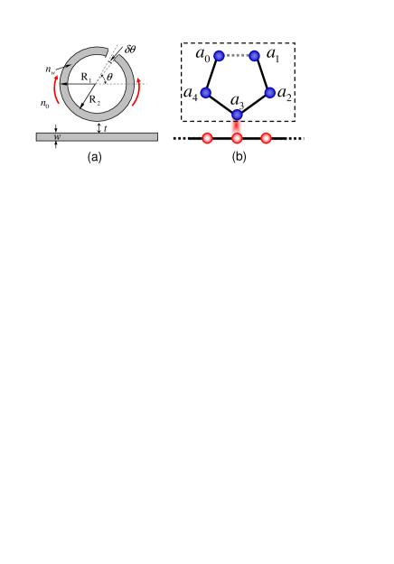
The elementary units under investigation is schematically illustrated in Fig. 1(a). The defected ring resonator is evanescently coupled to the signal waveguide. For perfect ring, it supports the clockwise(CW) and counter clockwise(CCW) traveling wave and there is no interaction between the two traveling wave modes. However, the scattering of the defected notch causes the recombination of the CW and CCW modes. In the context of CMT little98opt , the notched ring is mapped to the coupled double-ring resonator and the notch in single ring plays the role of the gap, which couples the double rings. Here, we treat the defected circular resonator as the discrete coupled cavity array with coupling constant different at the defected area, which is illustrated in Fig. 1(b). The array consists of resonators with tight-binding coupling. The notch in the ring is marked with a dashed line. The Hamiltonian here reads
| (1) |
where is the creation operator for photon with energy the cavity and is the tunneling strength between nearby cavities with defected induced inhomogeneous coupling . By the Fourier transformation , the Hamiltonian in the momentum space reads . In the rotation wave approximation, we keep only term and obtain the Hamiltonian as , where . Physically, and stand for the CW and CCW traveling wave, which has been introduced phenomenally in CMT. The coupling between the two modes is induced by the defect of the inhomogeneous of tunneling . Diagonalizing the Hamiltonian with unitary transformation and for , we obtain
| (2) |
where and
| (3) | |||||
| (4) |
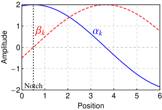
are the eigen-modes of the notched ring. And they were related to photonic molecule in Ref. bayer98prl ; pdyang06prl . Actually, this single defected notch induced the split of the degenerate resonant peak of CW and CCW traveling wave. The splitting can be probed by checking the transmission rate in the waveguide, which will be investigated in the following parts. Actually, those modes correspond to a symmetric and antisymmetric state with respect to the notch. The amplitude for the modes and is illustrated in Fig. 2. In this discrete model of the ring resonator, the position of notch should between the resonator and , namely . Thus for the mode, the amplitude of the field at the notch is at maximum. However, there is no field in the notch for the mode.
To probe the optical property of the resonator, a transmission line waveguide is introduced to couple the signal in the microcavity. Physically, the waveguide can be optical fiber, nanowire and defected lines on photonic crystal for different systems. Here, we also model the transmission line waveguide as the discrete coupled resonator, which is illustrated in Fig. 1(b). Each resonator couples to the near-by resonators by means of photon hopping. Those coupled-resonator array has been proposed to be a new type of optical waveguideyariv99opl . The Hamiltonian for the transmission line waveguide here reads
| (5) |
where is the bosonic creation operator for photon on the resonator. The tight-binding Hamiltonian here is a good approximation for modeling the coupled resonator array, which is proved in Ref. yariv99opl . And in Ref. lan08 , it is showed the model is equivalent to the simple dielectric waveguide under the linear dispersion area with right going wave and left going wave as showed in Ref. fan98 . The waveguide couples to the cavity at the -th resonator as the tunneling between 0-th resonator and the -th resonator of the ring resonator . The total Hamiltonian for this elementary unit reads . For the single photon case, the eigenwave stationary scattering function can be written as
| (6) |
where is the amplitude of photon in the resonator on the waveguide and () is the amplitude of photon on the resonator with mode (). Substituting the stationary scattering function into the time-independent Schrödinger equation , one can obtain equations for the amplitude of the site as
| (7) | |||||
| (8) | |||||
| (9) |
When the incident energy coincides with the energy of mode, namely , the amplitude by Eq. (8) and by Eq. (9). Thus only mode is excited here and the Ez-field at the notch is at maximum. When the incident energy is resonant with the energy of mode, namely , the amplitude by Equation(9) and by Equation(8). Here, only mode is excited and the amplitude of the field is zero. This phenomena has been numerically predicted in Ref. little98opt .
For the scattering process, the photon incidents from the left side of the line waveguide and is partially reflected by the notched ring resonator array. The amplitude in the waveguide reads , where () is the reflection(transmission) coefficient of the photon. The coefficient of the transition here is obtained
| (10) |
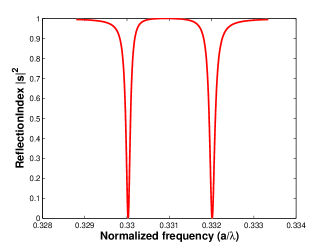
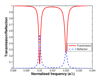
where . The reflection rate peaks at the resonance with the internal ring mode , where the optical signal is totally reflected. To see this resonant filtering effect, we plot the transmission rate verse the the incident energy of photon in Fig. 3(a). For comparison, a rigorous FDTD taflove simulation is performed with free available code F2P qiu for Transverse-Magnetic mode. The simulation is performed with the following parameter: , , , , and , where . The transmission and reflection rate is plotted in Fig. 3(b) around the resonant frequency . In Fig. 3(a), the parameters for this defect ring resonator unit are chosen to fit the numerical simulation: , , and . Therefore, our model confirms the function of the filter and its mechanism. However, we should notice a drawback to this approach: the quantitative analysis will relies on the numerical simulation. At present, the coupling constant at the notch and between the transmission line and the resonator should be fitted by numeric simulation.
In conclusion, we have presented a theoretical investigation of the notched ring filter with discrete coordinate scattering methods. The detailed mechanism of the coupling between the clockwise and count-clockwise is revealed to be the inhomogeneous tunneling in the resonator array system. We have predicted some experimentally accessible results for the coherent transmission and reflection property and present detailed explanation to field amplitude distribution at the notch.
This work is supported by NSFC No.10474104, No. 60433050, and No. 10704023, NFRPCNo. 2006CB921205 and 2005CB724508.
References
- (1) K. J. Vahala, Nature 424, 839 (2003).
- (2) J. D. Joannoupoulos, R. D. Meade and J. N. Winn, Photonic Crystals: Molding the Flow of Light (Princeton U. Press), 1995.
- (3) P. J. Pauzauskie, D. J. Sirbuly, and P. Yang, Phys. Rev. Lett. 96, 143903 (2006).
- (4) B. Dayan, A. S. Parkins, T. Aoki, E. P. Ostby, K. J. Vahala, H. J. Kimble, Science 319, 1062 (2008).
- (5) B. E. Little, S. T. Chu and H. A. Haus, Opt. Lett. 23, 1570 (1998).
- (6) A. Taflove and S. C. Hagness, Computational Electrodynamics: The Finite-Difference Time-Domain Methods (Artech House, Boston,2000)
- (7) B. E. Little, S. T. Chu, H. A. Haus, J. S. Foresi and J.-P. Laine, J. Lightware Technol. 15, 998 (1997).
- (8) Lan Zhou, Z. R. Gong, Yu-xi Liu, C. P. Sun and F. Nori, Phys. Rev. Lett. 101, 100501 (2008).
- (9) A. Yariv, Y. Xu, R. K. Lee and A. Scherer, Opt. Lett. 24, 711 (1999).
- (10) J. T. Shen, S. Fan, Phys. Rev. Lett. 95, 213001 (2005); ibid. 98, 153003 (2007); Opt. Lett. 30, 2001 (2005)..
- (11) M. Qiu, F2P: Finite-difference time-domain 2D simulator for photonic devices, http://www.imit.kth.se/info/FOFU/PC/F2P/.
- (12) M. Bayer, T. Gutbrod, J. P. Reithmaier, A. Forchel, T. L. Reinecke, P. A. Knipp, A. A. Dremin, and V. D. Kulakovskii, Phys. Rev. Lett. 81, 2582 (1998).