Atomic clocks and coherent population trapping: Experiments for undergraduate laboratories
Abstract
We demonstrate how to construct and operate a simple and affordable apparatus for producing coherent effects in atomic vapor and for investigating their applications in time-keeping and magnetometery. The apparatus consists of a vertical cavity surface emitting diode laser directly current-modulated using a tunable microwave oscillator to produce multiple optical fields needed for the observation of coherent population trapping. This effect allows very accurate measurement of the transition frequency between two ground state hyperfine sublevels, which can be used to construct a coherent population trapping-based atomic clock.
I Introduction
Coherent interactions of electromagnetic fields with atoms and molecules are of much interest because they enable coherent control and manipulation of the quantum properties of light and matter. In particular, the simultaneous interaction of atoms with two or more light fields allows all-optical addressing of the microwave transition between long-lived spin states of alkali metals such as Rb or Cs. If the frequency difference of the two fields exactly matches the splitting between two hyperfine sublevels of the atomic ground state, the atoms are prepared in a non-interacting coherent superposition of the two states, known as a “dark state.” This effect is known as coherent population trapping.arimondo96PO Because the dark state exists only for a very narrow range of differential frequencies between the two optical fields, a narrow transmission peak is observed when the frequency of either optical field is scanned near the resonance, and thus this effect is often called electromagnetically induced transparency.fleischhauerRMP05 There are many important applications of these effects such as atomic clocks,vanier05apb ; comparo07pt ; wynandsnature magnetometers,fleischhauer94PRA ; hollberg04APL slow and fast light,boydreview quantum memory for photons,lukin03rmp ; lukin06opn and nonlinear optics at the single photon level.lukin00prl In recent years electromagnetically induced transparency and related effects have gone beyond atomic systems and have been adapted for more complex systems such as molecules, impurities in solid state crystals, quantum dots, optical microresonators, and other photonic structures.
Although the coherent control and manipulation of atomic and light quantum properties is becoming increasingly important in many areas of physics, there are only a few publications aimed at introducing undergraduate physics students to the concepts.BerkeleyNMOR The complexity and high cost of equipment for conventional electromagnetically induced transparency are the main obstacles in making these experiments more accessible for students with little or no experience in optics. In this paper we present an experimental arrangement that allows undergraduate students to observe electromagnetically induced transparency and study its properties, as well as to build an atomic clock and/or magnetometer by locking a microwave oscillator on a clock resonance in Rb atoms.
II Brief summary of relevant theory
A complete analytical treatment of electromagnetically induced transparency would include spontaneous transitions between different atomic levels and requires use of the density matrix formalism, which is not generally introduced to undergraduates. However, the essence of the effect can be easily demonstrated using wave functions.griffiths
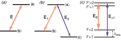
We first briefly review the important results regarding the interaction of a two-level atom with an electromagnetic field (see Fig. 1(a)). In this case an atom can be in a superposition of two atomic states and , which are eigenstates of the unperturbed atomic Hamiltonian such that
| (1) |
Normally, all atoms are in their ground state, but an oscillating electromagnetic field can vary the populations by exciting atoms to the an excited state. Thus, we expect to find the atomic wave function in the form
| (2) |
where the coefficients are functions of time and the probability of finding an atom in this state is . To find these coefficients we need to solve the time-dependent Schrödinger equation
| (3) |
where . The interaction part of the Hamiltonian contains information about the interaction of atoms with the electromagnetic field . When the light is nearly resonant, that is, when its (angular) frequency is close to the frequency difference between two atomic states , it is convenient to use the rotating wave approximation. This approximation neglects the fast oscillating part of the solution (proportional to ), which averages out at the detection stage, and keeps track of only measurable slow changes on a time scale proportional to . In this case the only two non-zero matrix elements of the interaction Hamiltonian aregriffiths
| (4a) | ||||
| (4b) | ||||
Here is proportional to the light field amplitude:
| (5) |
where the parameter is the matrix element of the electron dipole moment, whose value is determined by the intrinsic properties of an atom and characterizes the strength of interaction with an external electromagnetic field.
To find the equations describing the time evolution of the state coefficients and , we need to substitute the wavefunction in Eq. (2) into the Schrödinger equation (3) and then use the orthogonality conditions for the wave functions, , to find:
| (6a) | ||||
| (6b) | ||||
The solution of Eq. (6) is well-known:griffiths the atomic population cycles between the ground and excited states at the frequency . Such oscillations are called Rabi flopping, and the parameter is usually called the Rabi frequency.
Thus far we have considered only stimulated transitions between two atomic states, which occur when the jumps between two atomic states are caused solely by an electromagnetic field. In this case atoms repeatedly absorb and emit photons of the incident electromagnetic field, and no energy is lost in the process. This picture is not completely accurate, because it does not take into account the finite lifetime of the excited state. When atoms are in the excited states, they can spontaneously decay into the ground state by emitting a photon in a random direction, so that the energy carried out by this photon is lost from the original light field. As a result, some fraction of resonant light is absorbed after the interaction with atoms.
We now return to the main topic of interest for our experiment – the interaction of three-level atoms with two nearly-resonant laser fields, forming the configuration shown in Fig. 1(b). In this case the state of such an atomic system is given by a superposition of all three states:
| (7) |
In the following we assume that the lifetimes of the ground states and are very long, and the excited state spontaneously decays to the ground states at the average rate of . We also assume that each of the electromagnetic fields interacts with only one atomic transition – the field couples the states and , and the field couples the states and . This assumption means that the only non-zero matrix elements of the three-level system interaction Hamiltonian are and and their complex conjugates. If we follow the same steps as for a two-level system, we arrive at the following equations for the coefficients of the wavefunction in Eq. (7):
| (8a) | ||||
| (8b) | ||||
| (8c) | ||||
We have so far neglected the finite lifetime of the excited state . To properly account for it we have to use more sophisticated density matrix formalism.lukin03rmp However, the optical losses due to spontaneous emission should be proportional to the population of the excited state . Thus, if we can prevent atoms from getting excited, no energy will be dissipated, and the light field will propagate through atoms without any absorption. Let’s examine Eq. (8a) more closely and find the condition for which at all times. This condition corresponds to cases for which no atoms from either ground state are excited at any time even in the presence of the light fields, and there is no atomic population in the excited state (), and therefore no light is absorbed. It is easy to see that this condition is possible only when:
| (9) |
Because the phases of laser fields are usually constant, Eq. (9) requires that , which can be rewritten as
| (10) |
This condition is often called a two-photon resonance, because it requires the difference of the frequencies of two light fields to match the frequency splitting of two metastable states . For the exact two-photon resonance the condition (9) becomes much simpler: . If we substitute the coefficients into the general expression for the wave function (7) and choose the proper normalization, we find that there exists a non-interacting quantum state of the atomic system that is completely decoupled from the excited state:
| (11) |
Any atom in state never gets excited to the level , and the sample viewed from the side stays dark due to the lack of spontaneous emission. For that reason such a quantum state is often called a “dark state,” in which the atomic population is “trapped” in two lower states.
We can now understand what happens when an atom enters the interaction region. Before interacting with light the atomic population is equally distributed between two low energy states; that is, half of the atoms are in the state and half are in the state . It is very important to distinguish this statistical mixture from the coherent superposition of two states . During the interaction with light the atoms are excited to state , and then spontaneously decay either into the dark state, or into its orthogonal counterpart, the bright state. The atoms in the dark state do not interact with the laser fields and remain in this state for as long as it exists. The atoms in the bright state interact with the applied fields, so that they go through an excitation and spontaneous decay cycle many times before all atoms end up in the dark state. After such a steady state is achieved, the atomic medium becomes transparent, because both resonant light fields propagate without any optical losses. Note that the dark state is a coherent superposition of the two atomic states and , and is sensitive to their relative phase. That exchange requires the two optical fields to maintain their relative phase at all times in order for atoms to stay “invisible” to the light fields. That is why this effect is called coherent population trapping.
We now discuss what happens to light transmission if the frequency of one of the lasers is changing. If the system is not exactly at the two-photon resonance, a small two-photon detuning causes a slow variation in the relative phase of the two ground states:
| (12) |
If the two-photon detuning parameter is small, we can still use the dark state formalism as long as . At longer times such a “disturbed dark state” starts interacting with the laser fields, causing non-zero atomic population in the excited state and associated optical losses due to spontaneous emission.
So far we have allowed atoms to remain in the dark state indefinitely. In a real system some decoherence mechanisms are present to disturb a quantum state by randomizing its phase or forcing atoms to jump between two random energy levels. Even under perfect two-photon resonance atoms cannot be in the dark state longer than a characteristic dark state lifetime . Therefore, even for small non-zero two-photon detuning, the transparency remains if the additional phase accumulated by the dark state during its lifetime is small, . For larger two-photon detuning the dark state no longer exists, and the amount of light absorption becomes large. Thus we can characterize the width of the coherent population trapping resonance, that is, the range of two-photon detunings where transmission is still high. The exact expression of the width can be found only using a more complete treatment:vanier05apb
| (13) |
For stronger laser fields coherent population trapping resonance is broadened (“power broadened”), but the ultimate width is limited by the inverse lifetime of the dark state.
We have discussed an idealized three-level atom, but no such atoms exist in nature. It is possible to realize a three-level system in alkali metals very similar to one we have considered. In these elements, two non-degenerate hyperfine states of the ground level are used as states and , and the electron state or becomes the excited state . Because spontaneous radiative decay between two hyperfine states of the same ground level is strictly forbidden, an atom can stay in either state until it interacts with its environment.
It is now possible to preserve the quantum state of atoms for up to several seconds, but it requires using cold atoms or exotic chemical coatings. In a regular vapor cell (a sealed glass cell filled with alkali metal vapor at about room temperature) the main limitation of the ground state lifetime is the motion of atoms. Once an atom leaves the laser beam, it is likely to collide with the glass wall and thermalize and lose any information about its previous quantum state. For a mm laser beam the interaction time of an atom is limited to a few s, which corresponds to a coherent population trapping linewidth of tens or even hundreds of kHz. Sometimes a buffer gas — usually a non-interacting inert gas — is added to the vapor cell together with alkali metal. In this case alkali atoms diffuse through the laser beam rather than moving ballistically, thus increasing the interaction time by a few orders of magnitude, producing narrower coherent population trapping resonances.
III Experimental setup
Diode lasers are an ideal choice for working with alkali metals (K, Rb, Cs)steck because they are affordable, reliable, and easy to operate, and cover the right spectral range. The exact output frequency of a diode laser can be fine-tuned by changing the driving current and/or the temperature of the diode. In our experiments we use a laser resonant with the line of 87Rb (wavelength nm). A different Rb isotope or any other alkali metalwynandsvcsel ; wynandsD1D2 ; merimaaJOSAB03 can be used to reproduce the experiments described in the following with an appropriate change in the operational parameters.
The level structure of the 87Rb line is shown in Fig. 1(c). Both the ground () and the excited () states are split due to the coupling of the electron angular momenta and the nuclear spin, and each state is labeled with the value of the total angular momentum . The observation of coherent population trapping requires two laser fields to couple both ground states and with the same excited state ( in our experiments). However, it is impossible to use two independent diode lasers due to their relatively large intrinsic frequency noise. On one hand, a dark state (12) exists only if the differential frequency of two laser fields matches the ground state splitting with good precision (typically better than a few kHz). On the other hand, the electromagnetic field emitted by a laser is not truly monochromatic, but instead its frequency “jumps” randomly in a certain range, called the laser linewidth. Typical linewidths of commonly used diode lasers are from 10–100 MHz for a free-running diode laser to several hundred MHz for a vertical cavity surface emitting diode laser (VCSEL). Even more sophisticated commercial external-cavity diode lasers have linewidths of the order of 1 MHz. As a result, the two-photon detuning of two independent lasers fluctuates in the range determined by the laser linewidths, and no narrow resonances can be observed.
To avoid this problem we obtain several electromagnetic fields from a single laser by modulating its phase . Such phase modulation is equivalent to producing a frequency comb with the frequency separation between the “teeth” equal to the modulation frequency , and the amplitude of each component determined by the phase modulation amplitude :mathbook
| (14a) | ||||
| (14b) | ||||
In our experiments we use phase modulation frequency to be close to the hyperfine splitting frequency in 87Rb GHz. We then use two of the resulting frequency comb components to form a system: the zeroth (at the carrier frequency ) and one of the first (at frequency ) modulation sidebands. It is also possible to phase modulate the laser field at half of the hyperfine splitting frequency, and use two first modulation sidebands to achieve coherent population trapping.vanier05apb A special type of diode laser (a VCSEL)wynandsvcsel allows efficient phase modulation at the desired high microwave frequency by directly modulating its driving current. For this type of laser an active region (where the lasing occurs) is smaller than in conventional edge-emitting diode lasers, providing two main advantages: fast response (up to 10 GHz modulation was achieved for our sample), and very low power consumption. Both of these properties make a VCSEL the laser of choice for miniature atomic clock applications.vanier05apb
In the following we give a detailed description of the experimental apparatus in our laboratory.NathanThesis An approximate budget for the experiment is provided in Table I.
| Component | Source | Price | Quantity |
| Laser assembly | |||
| VCSEL laser @795 nm | ULM795-01-TN-S46FOP, Laser components | $400 | 1 |
| for different wavelengths | VCSEL-780 or -850 Thorlabs | $20 | |
| Collimating tube | LDM-3756, Optima Precision | $75 | 1 |
| Bias-T | ZX85-12G+, Mini-Circuits | $100 | 1 |
| Temperature controller | WTC3293, Wavelength Electronics | $500 | 1 |
| TEC element | 03111-5L31-03CP, Custom Thermoelectric | $20 | 1 |
| Optical isolator (optional) | IO-D-780-VLP, Thorlabs | $460 | 1 |
| Rubidium cell enclosure | |||
| Rb cell: isotopically | |||
| enriched/natural abundance | Triad Technology | $625/$310 | |
| Bifiler heating wire | 2HN063B-13 Ari Industries | $4/ft | |
| Magnetic shielding | |||
| Custom 3 layer design | Magnetic Shield Corporation | $1300 | 1 |
| alternative: lab kit | $100 | ||
| Microwave equipment | |||
| Tunable Mini-YIG Oscillator | Stellex, purchased used on eBay | $50 | 1 |
| Linear PLL chip evaluation board | LMX2487EVAL National Semiconductor | $176 | 1 |
| Voltage controlled oscillator | CRO6835ZZ Communications | $75 | 1 |
| 10 MHz reference oscillator | 501-04609A Streamline | $305 | 1 |
| Output rf amplifier Amplifier | ZJL-7G Mini-Circuits | $100 | 1 |
| Various attenuators | VAT-x Mini-Circuits VAT-x | $16/each | 3–4 |
| Directional coupler | 780-20-6.000 MECA Electronics | $165 | 1 |
| Various optics and opto-mechanics | |||
| Mirrors | Thorlabs (various options) | $15–$50 | 2–3 |
| Quarter wave-plate | WPMQ05M-780 Thorlabs | $230 | |
| Photodetector | Thorlabs (various options) | $20–$100 | |
| Optical mounts & holders | Thorlabs | ||
| General lab equipment | |||
| Oscilloscope, function generator, lock-in amplifier, frequency counter, constant V and V and variable power supplies, multimeters. | |||
| ∗ Additional items are needed if DAVLL laser lock is used. | |||
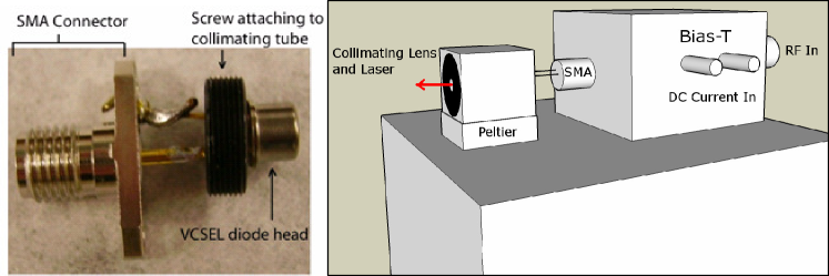
Laser assembly. Figure 2 shows the homemade laser head assembly used in our experiment. A VCSEL (ULM795-01-TN-S46FOP from U-L-M Photonics) is placed inside a collimating tube (model LDM 3756 from Optima Precision) and a copper holder. The resulting assembly is attached to a peltier thermoelectric cooler connected to a temperature controller (model WTC3293-14001-A from Wavelength Electronics) to actively stabilize the diode temperature with precision better than C. The basis for the laser system is the heat sink, which doubles as the holding block for the system. The sensitivity of the laser frequency to temperature ( nm/∘C for our laser) introduces a way to tune the laser to the atomic resonance frequency, but also puts stringent requirements on the diode’s temperature stability. To prevent temperature fluctuations due to air currents, the laser mount is enclosed in a small aluminum box.
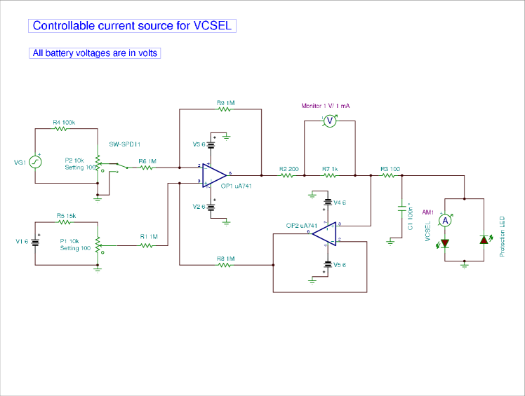
The laser diode pins are soldered to a standard SMA connector and plugged into a Bias-T (model ZFBT-6GW from Mini-Circuits), which combines a high-frequency modulation signal and a constant current, required to drive the VCSEL. A typical driving current required to power a VCSEL is very small (the maximum allowed current is 3 mA in our sample). To extend the lifetime of the diode, we operated it at 1–1.5 mA, resulting in an output optical laser power of mW, collimated to a mm beam. Any variations in laser current also cause fluctuations in the output laser frequency ( nm/mA). We have designed a simple, battery-operated, low-noise current supply optimized to drive a VCSEL (Figure 3 provides the schematics.) For the coherent population trapping and clock measurements, the output laser frequency is also actively locked to the atomic transition using a DAVLL (Dichroic Atomic Vapor Laser Locking) technique.davllwieman ; DAVLLbudker
Microwave modulation. In addition to a constant driving current, a high-frequency signal has to be mixed in to phase-modulate the output of the laser and produce the frequency comb given by Eq. (14). In our experiments we tested several microwave oscillators. Our initial tests used a commercial frequency synthesizer (Agilent E8257D) available in our laboratory. For all later work it was replaced with less expensive options: a current-tunable crystal oscillator and an electronic phase-locked loop (PLL) with external 10 MHz reference.
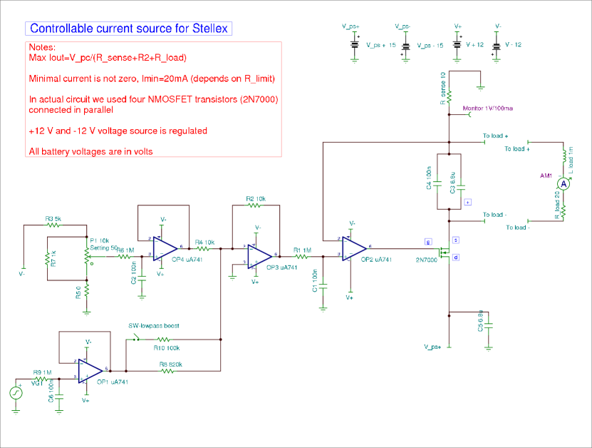
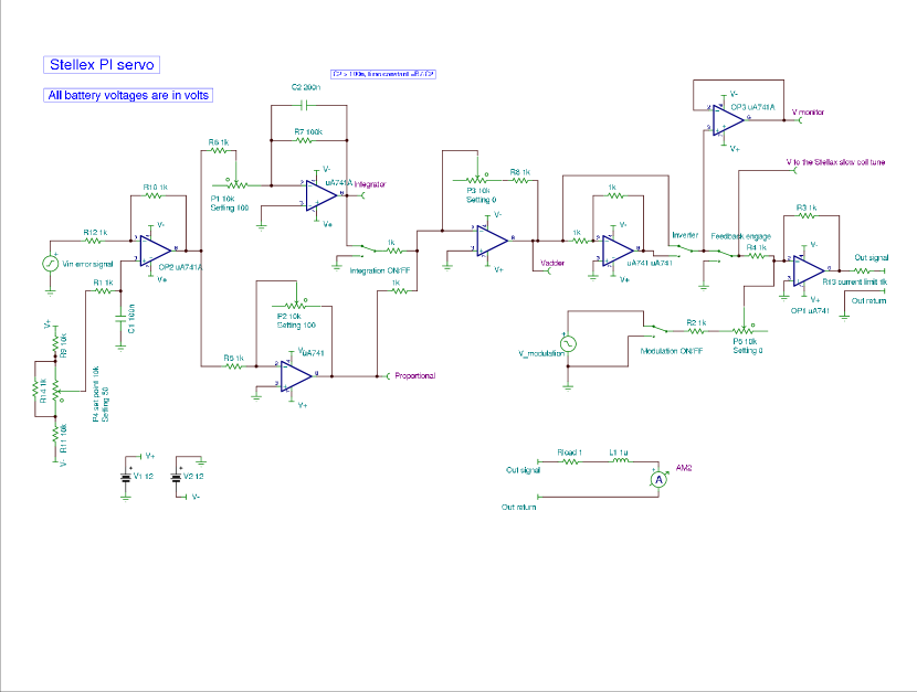
The most affordable rf source was a Stellex Mini-YIG oscillator purchased from a surplus electronic seller. This oscillator outputs 15 dBm of power at a frequency between 5.95 GHz and 7.15 GHz. The output frequency of the oscillator can be tuned by changing the current flowing through two internal magnetic coils: a main coil, designed for coarse tuning of the oscillator frequency (5 MHz/mA) at a slow rate up to 10 kHz, and an auxiliary fast tuning coil that allows finer frequency control (150 kHz/mA) with the 400 kHz tuning bandwidth. As for the VCSEL driver, a current source used for tuning must have minimal internal noise (better than many commercial laser current drivers), because any modulation frequency fluctuations are immediately converted into fluctuations of the two-photon detuning. In our case the tuning current required to reach the designed oscillator frequency ( GHz) is greater than 100 mA. To simplify the construction of a tunable low-noise high-current source, we used a two-stage design. The oscillator frequency is coarsely set to the required value by manually adjusting a cw current source driving the main tuning coil to approximately 140 mA, and an additional tunable low-current source plugged into the auxiliary fast tuning coil is responsible for fine frequency adjustments in the narrow range of about 1 MHz around the set value. Circuits for the oscillator current driver and for the active locking servo are shown in Figs. 4 and 5. The tuning source allows tuning the oscillator frequency to a particular microwave frequency or sweeping the modulation frequency to observe changes in the optical transmission as a function of the two-photon detuning. Although all the experiments we discuss can be performed using the Stellex oscillator, it is sometimes not very convenient to use because of its large internal frequency jitter at the level of several tens of kilohertz. Also, without active frequency locking, its frequency drifts several hundreds of kilohertz during an hour, probably because of its poor temperature stability.
The other microwave source we used requires more initial investments, but provides much greater precision and stability in the output frequency. It is based on the Linear PLL chip (LMX2487) evaluation board (LMX2487EVAL), which sets a user provided voltage controlled oscillator at an arbitrary frequency near 6.835 GHz with sub-Hertz resolution (we used CRO6835Z). The output signal is phased-locked to a 10 MHz reference. This feature can be used, for example, to lock the rf output to a stable frequency reference (such as a benchtop Rb frequency standard FS725 from Stanford Research Systems). Also, we can slightly vary the frequency of a voltage-controlled 10 MHz oscillator to achieve sweeping capability in the rf output frequency. We used a Streamline oscillator (501-04609A) with a voltage tuning response of Hz, corresponding to a variation in the microwave frequency of kHz. This tuning is sufficient to lock the rf output to the coherent population trapping resonance and study its stability in an atomic clock arrangement.
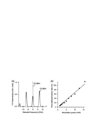
The microwave output of either oscillator is connected to the laser through the bias-T. The power of the oscillator determines the strength of the modulation. Figure 6(a) shows the modulation comb for two values of rf power recorded by passing the laser output through a hand made Fabry-Perot cavity with 40 GHz free spectral range. Figure 6(b) shows the ratio between the first and the zeroth (carrier) modulation sidebands, which grows proportionally to the microwave power sent to the VCSEL. Due to the high efficiency of the high-frequency current modulation, we were able to transfer a large fraction of the optical power in the first modulation sideband, achieving the first sideband/carrier ratio for moderate modulation power mW (12 dBm).
Rubidium cell enclosure. The remaining important component of the experimental setup is a Rubidium cell. In our experiment we used a standard cylindrical glass cell ( mm diameter, mm length) containing isotopically pure 87Rb (TT-RB87/Ne-75-Q from Triad Technology). It is easy to estimate that at room temperature, Rb atoms inside the cell move with average speed of m/s, and thus it takes only s to cross the mm-wide laser beam.timeofflightnote After that time an atom most likely collides with the cell wall, and its quantum state created during the interaction with the laser fields is destroyed. To amend the situation, our cell also contains Torr of Ne buffer gas. Collisions with buffer gas atoms have a very weak effect on the atomic quantum state, but rapidly change the velocity of Rb atoms, restricting their motion to slow diffusion. As a result, Rb atoms spend a much longer time inside the interaction region, effectively increasing their dark state lifetime. For example, for Rb atoms in Ne buffer gas, the diffusion time of an atom through the laser beam diameter can be calculated by solving the diffusion equation. The solution is given byarimondoPRA96
| (15) |
where is the pressure of the Ne buffer gas inside the cell, and is the atmospheric pressure. For example, for the mm beam used in the experiment, Torr of Ne buffer gas extends the interaction time from s to s. The exact total amount and composition of a buffer gas is not critical. Any cell with 5–50 Torr of any inert gas (Ne, He, Ar, Xe) or some simple diatomic molecules (N2, CH4) is suitable for the experiments described in the next sections.
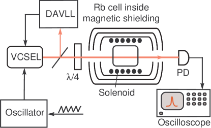
Any longitudinal magnetic field splits the magnetic sublevels of all hyperfine states due to the Zeeman effect, and thereby changes their two-photon resonance frequencies. To avoid stray fields from the laboratory environment, the Rubidium cell is placed inside a set of three cylindrical magnetic shields (from Magnetic Shield Corporation) to suppress any external magnetic field by a factor of –. Much simpler single-layer shielding may be sufficient to observe coherent population trapping resonances of a few tens of kHz wide. It might also be useful to install a solenoid inside the shielding to change the longitudinal magnetic field and study its effect on coherent population trapping.
The number of Rb atoms interacting with light (that is, the Rb vapor density inside the cell) is determined by the saturated vapor pressure with the solid or liquid Rb metal droplet placed inside the cell, and can be controlled by changing the cell’s temperature.steck In our experiment we control the temperature of the cell by passing constant electrical current through a resistive heater wrapped around the inner magnetic shield. To avoid any magnetic field due to the heater current, we used a bifiler chromium wire as a heating element. Alternatively, any twisted loop of wire can be used, because the current will run in opposite directions along each point of the wire. We found that the coherent population trapping resonances have the highest contrast at some optimal range of temperatures (35–50∘C for our experiment). If the temperature is too low, almost all the light gets through regardless of coherent population trapping conditions. If the temperature is too high, it is difficult to see coherent population trapping resonances due to strong absorption.
IV Observation and characterization of coherent population trapping resonances
Our experimental apparatus enables a range of experiments on the coherent properties of atoms and their applications. The first and basic one is the observation of coherent population trapping resonances by measuring the transmission of the laser light through the atomic cell while scanning the laser modulation frequency over the two-photon resonance. The first step in this process is tuning the laser to the right optical frequency. Figure 8 shows the transmission of the laser light when its frequency is swept across all four optical transitions of the 87Rb line [the transitions are shown in Fig. 1(c)]. The spectral width of each absorption line is determined by the decoherence rate of the optical transitions of approximately MHz FWHM (dominated by the Doppler broadening). As a result, the two transitions from the same ground state to each of the excited states are not completely resolved, because their relatively small hyperfine splitting ( MHz) is comparable to the width of each individual transition. The transitions from each of two ground states are clearly separated due to significantly larger ground-state hyperfine splitting ( GHz).
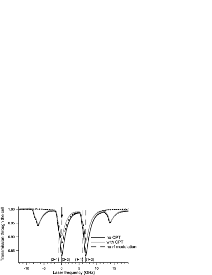
The output optical frequency of the laser is sensitive to the rf modulation power, and the precise tuning should be performed with modulation turned on. The tuning process is more convenient if the optical power in each of the first modulation sidebands is –60% of the carrier field, so it is easy to distinguish the carrier and sideband absorption. Then the rf oscillator frequency should be appropriately tuned – first with the coarse tuning to a value close to the hyperfine splitting, and then with fine adjustments such that a clear increase in light transmission is observed near Rb resonances, as illustrated by the difference in the solid lines in Fig. 8. To achieve the maximum contrast of coherent population trapping resonances with circularly polarized light, the carrier (that is, the unperturbed laser frequency) should be tuned to the transition. In this case, the high-frequency modulation sideband is resonant with the . This arrangement is indicated by an arrow in Fig. 8.
Once the laser optical frequency is parked at the right transition, we can directly observe a coherent population trapping resonance by slowly scanning the modulation frequency near the two-photon transition. Figure 9 shows examples of narrow (a few kHz) peaks in the transmitted light power after the Rb cell when the coherent population trapping condition is fulfilled. Because all the laser light is detected, the coherent population trapping transmission peak is observed on top of an often large background. This background transmission consists of the off-resonant modulation sidebands, which do not interact with atoms, as well as residual transmission of the resonant light fields, if the atomic density is not too high. It is also easy to see that even the maximum of the coherent population trapping resonance does not reach 100% transmission, because the lifetime of the dark state is finite, and there is always a fraction of atoms in the laser beam that is absorbing light. The exact position of the transmission maximum depends on many parameters, such as the power of the light (“light shift”), and the amount and the temperature of the buffer gas (“pressure shift”). For example, in the cell we used in the experiments (filled with Torr of Ne) the position of the two-photon resonance at low light level was measured to be GHz.
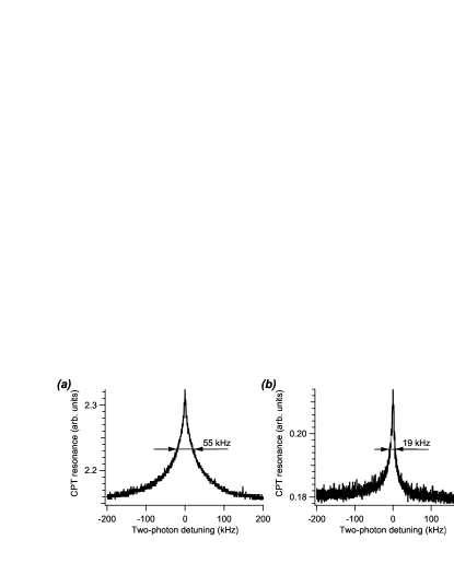
After initial detection of coherent population trapping resonances, it may be useful to systematically study important properties such as the dependence on the laser field strength. For example, Eq. (13) predicts the broadening of coherent population trapping resonances at higher laser powers. It is easy to verify this broadening experimentally by measuring the resonance width while reducing the light power interacting with atoms by placing (for example) a few neutral density filters in front of the cell. The example of the resonance narrowing is shown in Fig. 9. Note that the resonance linewidth may not follow Eq. (13) exactly, especially for moderate buffer gas pressure ( Torr), because the dynamics of atomic diffusion becomes important. In particular, if atoms are allowed to diffuse out of the laser beam and then return without losing their quantum state,xiaoPRL06 the width of the coherent population trapping resonances may become much narrower than expected from the simple diffusion picture provided by Eq. (15).
We can also observe that the coherent population trapping resonance lineshape becomes asymmetric when the optical laser frequency is detuned from the exact optical transition frequency.mikhailovPRA04 This effect can be used to fine tune the laser frequency to the resonance position, which corresponds to the most symmetric coherent population trapping resonance. At the same time, students may find it interesting to observe this systematic lineshape change, accompanied by the reduction of the resonance amplitude and growth in background transmission as fewer and fewer atoms interact with the laser fields.
V Effect of the Zeeman structure on coherent population trapping resonances; atomic magnetometer
So far we have ignored the fact that each hyperfine sublevel consists of magnetic (Zeeman) sublevels characterized by . These sublevels are degenerate in zero magnetic field, but if a magnetic field is applied along the light propagation direction (for example, by running the current through the solenoid mounted inside the magnetic shielding), the sublevels shift by an amount proportional to the applied magnetic field :
| (16) |
where is the magnetic quantum number for each sublevel, and is the gyromagnetic ratio. For Rb levels the gyromagnetic ratios are very small (M Hz/G and MHz/G),steck and a high magnetic field is required to shift the levels far enough to resolve individual optical absorption resonances from different Zeeman sublevels. In contrast, coherent population trapping resonances are much more sensitive to level shifts.
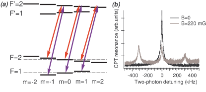
Let’s look more carefully at what happens to a coherent population trapping resonance in the presence of a magnetic field. Figure 10(a) shows the relevant Rb energy levels taking into account their magnetic structure. In this case we must consider not one, but three independent systems formed by the carrier and high frequency sideband fields between three pairs of magnetic sublevels in the ground states and magnetic sublevels , 1, and 2 (or , , and depending on which circular polarization is used). When these levels are degenerate (no magnetic field) the dark state is formed at each pair of ground state sublevels at the same rf frequency . If the oscillator frequency is swept around this value, only one coherent population trapping peak is observed. However, in the presence of an applied magnetic field, the magnetic sublevels with different magnetic quantum numbers shift by different amounts, as shown in Fig. 10(a). The conditions for the two-photon resonance at are obeyed only for the non-shifted pair, and for levels the resonance now occurs at . As a result, the original single coherent population trapping peak splits into three peaks as shown in Fig. 10(b). The frequency difference between the peaks is proportional to the applied magnetic field, and can be used as a sensitive magnetometer.
VI Coherent population trapping-based atomic clocks
Before discussing the application of coherent population trapping resonances for atomic clocks, it is helpful to mention the definition of the second. The second is the duration of 9 192 631 770 periods of the radiation corresponding to the transition between the two hyperfine levels of the ground state of the cesium-133 atom.bipm This definition implies that we have to accurately measure the frequency between two hyperfine states of Cs, and then count the number of oscillations to determine the duration of one second. For clocks it does not matter much if another alkali metal atom is used instead of Cs, because the hyperfine splitting of most of them is known with great precision. Thus, the principle of an atomic clock is simple. A frequency of some rf oscillator has to be locked to match the frequency difference between two hyperfine states of Cs or Rb (“clock transition”), and then the oscillation periods of this locked oscillator can be used as tick marks for measuring time. The international time standard at the National Institute of Standards and Technology, a Cs fountain clock, operates on this principle by directly probing the clock transition using microwave radiation. Extreme care is taken in this case to avoid any systematic errors in measurements to ensure relative frequency stability approaching . However, many practical applications could benefit from an atomic clock whose stability is at the level of –, so long as such a device is compact, robust, and power-efficient. In particular, coherent population trapping resonances are very attractive for the development of miniature atomic clocks, because all optical components can be miniaturized without loss of performance,hollberg04APL and no bulky rf cavity is needed. Because the coherent population trapping resonance occurs exactly when the frequency difference between two optical fields matches the hyperfine splitting in Rb (the clock transition), a coherent population trapping-based atomic clock can be constructed by locking the rf oscillator used to modulate the VCSEL to the maximum transmission through the atomic cell.
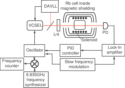
To realize such feedback in our experiment, a few additional pieces of equipment were added to the setup, as shown in Fig. 11. First, a slow dithering modulation (5–10 kHz) was superimposed on top of the oscillator rf frequency. When the oscillator frequency is within a coherent population trapping resonance, this modulation induces a corresponding modulation in the output optical transmission. Phase-sensitive detection of this signal using a lock-in amplifier transforms a symmetric transmission peak to an anti-symmetric error signal, which is zero at precisely the maximum of the coherent population trapping resonance. This error signal is then fed back to the tuning current of the oscillator to correct its frequency and prevent it from drifting from the clock transition frequency.
To evaluate the performance of the constructed atomic clock we need to measure the frequency stability of the locked oscillator that outputs the signal at about GHz. Although it is possible to measure a few GHz frequency with high enough precision (10 or 11 significant figures), the required microwave equipment is very expensive. Instead, we split a few percent of the oscillator output using a directional coupler (780-20-6.000 from MECA Electronics) and mix it with a stable reference frequency source at a similar frequency. The resulting beat signal is in the few megazertzs range, and can be accurately measured with the required precision using a standard frequency counter.
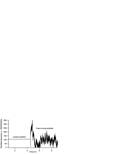
The difference in performance for the noisy Stellex oscillator when it is free-running or when it is locked to the coherent population trapping resonances makes the advantage of a coherent population trapping-based atomic clock more striking, as illustrated in Fig. 12. It is is easy to see a significant difference in oscillator stability. Although the frequency of the free-running oscillator fluctuates by kHz, the locked oscillator is stable within Hz.
A common measure of an oscillator’s stability is the Allan variance.allan2 To calculate the Allan variance we have to divide the entire set of frequency measurements into sampling periods of duration , and then calculate the average frequency value for each interval. The sum of the squared differences between the two consecutive sampling periods is a good quantitative measure of the variation of the average frequency during the time . The definition of the Allan variance is
| (17) |
The Allan variance depends on the averaging time and is usually displayed as a graph. The lower the Allan variance, the greater the stability of the oscillator. For a very stable but noisy oscillator the value of the Allan variance monotonically improves with larger , because longer integration time reduces the effect of random noise. However, any long-term systematic drift causes the Allan variance to grow once the duration of the sampling period becomes comparable to the characteristic drift time. Typically, the minimum in the Allan variance plot indicates the optimal averaging time for the given experiment.
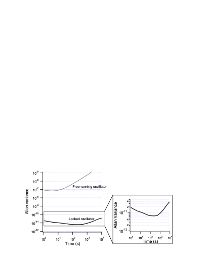
Figure 13 shows the Allan variance for the frequencies of the locked and the free-running oscillator. This plot clearly demonstrates close to four orders of magnitude improvement in the oscillator performance, from over a duration of 10 s in the free-running regime, to over 100 s in the regime of the coherent population trapping-based atomic clocks. To put this stability into perspective, a clock would lose 1 s every 4000 years if we could keep our clock that stable indefinitely. We also measured how long our clock stays locked to microwave clock transition. Our best attempt yielded a locking time of 41 h with a 6 Hz drift, which was most likely limited by the quality of the DAVLL optical lock.
VII Conclusions
We have presented the details of the construction of an affordable and versatile experimental apparatus for observing coherent effects in an atomic vapor suitable for an undergraduate laboratory. Assembly and debugging the apparatus is an appropriate task for a senior research project (the experimental apparatus described here was mainly designed and assembled by one of the co-authors (NB) during his senior year). Work with this apparatus will allow students to learn the basics of diode lasers, rf equipment, and atomic spectroscopy. We also described three experiments that can be realized using this apparatus. We first described the procedure for observing coherent population trapping transmission resonance due to manipulations of the coherent state of atoms. We then took advantage of the extreme sensitivity of the coherent population trapping resonance frequency to small shifts in the energy levels of atoms to measure a small magnetic field. Finally, we locked the rf oscillator frequency to the coherent population trapping resonance using a feedback mechanism to create a prototype atomic clock. The same apparatus also can be used for slow and stored light experiments if the amplitude of the microwave radiation can be shaped into probe pulses.
The ability to manipulate quantum states of an atom using light has led to several important applications, such as quantum memory and slow light, that are currently one of the most active and interdisciplinary areas of physics. lukin03rmp ; boydreview ; lukin06opn Familiarity with the basics of these effects through hand-on experience would be very beneficial for undergraduate students.
Acknowledgements.
The authors would like to thank Sergey Zibrov for advice on the experimental apparatus design, Chris Carlin for the help with the laser lock construction, and Nate Phillips and Joe Goldfrank for useful feedback on the manuscript. This research was supported by Jeffress Research grant J-847, the National Science Foundation PHY-0758010, and the College of William & Mary.References
- (1) M. D. Lukin, “Colloquium: Trapping and manipulating photon states in atomic ensembles,” Rev. Mod. Phys. 75, 457–472 (2003).
- (2) E. Arimondo, “Coherent population trapping in laser spectroscopy,” Prog. Opt. 35, 257–354 (1996).
- (3) M. Fleischhauer, A. Imamoglu, and J. P. Marangos, “Electromagnetically induced transparency: Optics in coherent media,” Rev. Mod. Phys. 77, 633–673 (2005).
- (4) J. Vanier, “Atomic clocks based on coherent population trapping: A review,” Appl. Phys. B 81, 421–442 (2005).
- (5) J. Comparo, “The rubidium atomic clock and basic research,” Phys. Today 60 (11), 33–39 (2007).
- (6) R. Wynands, “The atomic wrist-watch,” Nature 429, 509–510 (2004).
- (7) M. Fleischhauer and M. O. Scully, “Quantum sensitivity limits of an optical magnetometer based on atomic phase coherence,” Phys. Rev. A 49, 1973–1986 (1994).
- (8) P. D. D. Schwindt, S. Knappe, V. Shah, L. Hollberg, J. Kitching, L.-A. Liew, and J. Moreland, “Chip-scale atomic magnetometer,” Appl. Phys. Lett. 85, 6409–6411 (2004).
- (9) R. W. Boyd and D. J. Gauthier, “Slow and fast light,” in Progress in Optics 43, 497–530, edited by E. Wolf (Elsevier, Amsterdam, 2002), Chap. 6.
- (10) M. D. Eisaman, M. Fleischhauer, M. D. Lukin, and A. S. Zibrov, “Toward quantum control of single photons,” Optics & Photonics News 17, 22–27 (2006).
- (11) M. D. Lukin and A. Imamoglu, “Nonlinear optics and quantum entanglement of ultraslow single photons,” Phys. Rev. Lett. 84, 1419–1422 (2000).
- (12) D. Budker, D. J. Orlando, and V. V. Yashchuk, “Nonlinear laser spectroscopy and magneto-optics,” Am. J. Phys. 67, 584–592 (1999).
- (13) D. J. Griffiths, Introduction to Quantum Mechanics (Pearson Prentice Hall, Upper Saddle River, NJ, 2005), 2nd ed.
- (14) D. A. Steck. Alkali D Line Data, <steck.us/alkalidata/>.
- (15) C. Affolderbach, A. Nagel, S. Knappe, C. Jung, D. Wiedenmann, and R. Wynands, “Nonlinear spectroscopy using a vertical-cavity surface-emitting laser (VCSEL),” Appl. Phys. B 70, 407–413 (2000).
- (16) G. B. Arfken and H. J. Weber, Mathematical Methods for Physicists (Harcourt, San Diego, 2005), 6th ed.
- (17) M. Stähler, R. Wynands, S. Knappe, J. Kitching, L. Hollberg, A. Taichenachev, and V. Yudin, “Coherent population trapping resonances in thermal 85Rb vapor: D1 versus D2 line excitation”, Opt. Lett. 27, 1472–1474 (2002).
- (18) M. Merimaa, T. Lindvall, I. Tittonen, and E. Ikonen, “All-optical atomic clock based on coherent population trapping in 85Rb,” J. Opt. Soc. Am. B 20, 273–279 (2003).
- (19) N. Belcher, “Development of a prototype atomic clock based on coherent population trapping,” B. S. thesis, Department of Physics, The College of William & Mary (May, 2008); available at <ixnovi.people.wm.edu/publications/ClockDocs.html>.
- (20) K. L. Corwin, Z.-T. Lu, C. F. Hand, R. J. Epstain, and C. E. Wieman, “Frequency-stabilized diode laser with the Zeeman shift in an atomic vapor,” Appl. Optics 37, 3295–3298 (1998).
- (21) V. V. Yashchuk, D. Budker, and J. Davis, “Laser frequency stabilization using linear magneto-optics,” Rev. Sci. Instr. 71, 341–346 (2000).
- (22) Although such a calculation gives a good order of magnitude estimate of the coherence lifetime, some atoms moving along the laser beam interact with light much longer, giving rise to additional narrow resonances. See, for example, S. Briaudeau, D. Bloch, and M. Ducloy, “Sub-Doppler spectroscopy in a thin film of resonant vapor,” Phys. Rev. A 59, 3723–3735 (1999); A. Sargsyan, D. Sarkisyan, and A. Papoyan, “Dark-line atomic resonances in a submicron-thin Rb vapor layer,” Phys. Rev. A 73, 033803-1–7 (2006).
- (23) E. Arimondo, “Relaxation processes in coherent-population trapping,” Phys. Rev. Lett. 54, 2216–2223 (1996).
- (24) Y. Xiao, I. Novikova, D. F. Phillips, and R. L. Walsworth, “Diffusion-induced Ramsey narrowing,” Phys. Rev. Lett. 96, 043601-1–4 (2006).
- (25) E. E. Mikhailov, I. Novikova, Y. V. Rostovtsev, and G. R. Welch, “Buffer-gas induced absorption resonances in Rb vapor,” Phys. Rev. A 70, 033806-1–12 (2004).
- (26) The official site of Bureau International des Poids et Mesures is <www.bipm.org/en/si/base_units/>.
- (27) An overview of Allan variance is given by David W. Allan at <www.allanstime.com/AllanVariance/>.