The effect of Coulomb interaction at ferromagnetic-paramagnetic metallic perovskite junctions.
Abstract
We study the effect of Coulomb interactions in transition metal oxides junctions. In this paper we analyze charge transfer at the interface of a three layer ferromagnetic-paramagnetic-ferromagnetic metallic oxide system. We choose a charge model considering a few atomic planes within each layer and obtain results for the magnetic coupling between the ferromagnetic layers. For large number of planes in the paramagnetic spacer we find that the coupling oscillates with the same period as in RKKY but the amplitude is sensitive to the Coulomb energy. At small spacer thickness however, large differences may appear as function of : the number of electrons per atom in the ferromagnetics and paramagnetics materials, the dielectric constant at each component, and the charge defects at the interface plane emphasizing the effects of charge transfer.
1 INTRODUCTION
Magnetic multilayer films have attracted the attention of the physics community since the discovery of ”Giant magnetoresistance ” (GMR) in metallic superlattices by Baibich et al. [1] and have been the subject of intensive basic and applied research. The fundamental physics giving rise to GMR has been clarified, the role of RKKY interactions being prominent. Application to read heads of magnetic memories is already a reality. The oscillations in the magnetic coupling have been beautifully derived by analogy to the de Haas Van Alfven effect by D. M. Edwards et al.[2] and were used to calculate realistically the magnetic coupling between Co layers in CoCuCo trilayers [3]. A comprehensive discussion of the problem of interlayer coupling is given in Ref. [4]. Studies of metal to insulating oxides interfaces based on Density Functional Theory (DFT) are reported in Ref. [5]
On the other side, the discovery of ”Colossal magnetoresistance” by von Helmholt et al [6] in La1-xSrxMnO3 type compounds, has also polarized research on these materials, their phase diagrams as a function of composition and temperature have been determined, but even though there has been considerable progress, the basic physics of the bulk materials is not yet quite completely understood [7]. Furthermore, several magnetic oxide heterostructures based on colossal magnetoresistance materials have been the subject of important research, including magnetic coupling mediated by a metallic spacer [8],[9]. We study here the effect of the charge transfer (CT) at the interface on the magnetic coupling. RKKY being a perturbation theory can not be applied to these materials where the coupling energy between moments and conduction electrons is larger than the bandwidth. The theories mentioned before are appropriate for metallic magnets were screening is strong and Coulomb interactions play a minor role in the charge transfer at the interface. In this paper we focus on a trilayer formed by ferromagnetic-paramagnetic ferromagnetic ionic compounds and alloys where the Coulomb interaction dominates the charge transfer at the interface. We calculate self-consistely the charge profile in terms of a minimum set of parameters and study the effect of these parameters on the magnetic coupling between ferromagnetic layers. To this end, we build a Hamiltonian that contains the essential features of a fully-polarized ferromagnet (FF) and a paramagnetic metallic (PM) spacer and parametrize the interfaces in the simplest possible way.
2 MODEL
We study a model for electrons moving in a three layer structure (FF-PM-FF) formed by two N-cell units (N-c.u.) of half-metallic ferromagnetic perovskites, as for example La1-xSrxMnO3 () separated by M-c.u. of non-magnetic metal, as LaNiO3. The Mn and Ni sites form a simple cubic structure and we take the interfaces perpendicular to a cubic axis. La (Sr) at the center of the cubes form an other interpenetrating cubic lattice with opposite charge, so that La(Sr) planes are in between the Mn planes. We will consider this alternating planar structure as shown schematically in Fig. 1.

To describe the charge transfer between the different layers we follow the pioneer papers of Gorkov and Kresin [10] and Okamoto and Millis [11], and used more recently by Brey [12] to study manganite-insulator oxide interfaces. Since charge transfer at the interfaces is determined by the competition between kinetic energy and Coulomb energy we define a Hamiltonian for the kinetic energy of manganites , and for the spacer and a Coulomb Hamiltonian that accounts for the Coulomb interactions between electrons and the positive charges background, and between themselves. Because of the large intrasite Coulomb interaction and exchange energies, double occupation of the eg orbitals is inhibited. To include this fact in the model Hamiltonian we use a single spinless orbital in the Hamiltonian following previous models for manganites Ref.[13]. In manganites each Mn ion has three localized electrons in the orbitals which, due to Hund’s rule, produce a local spin , while the additional electrons are itinerant and have their spin parallel to the local spin again due to Hund’s rule. When both manganites layers are strongly ferromagnetic, the conduction electrons can be completely spin polarized parallel to the magnetization in each manganite region, the situation we are considering here. The itinerant electrons in the right and left FF regions can be modelled by a tight-binding Hamiltonian:
| (1) |
where identifies the planes and runs between and in the left FF layer and between and in the right one, run over nearest neighbors (n.n) layers, covers each plane in the layer, and run over n.n in the plane .
For the spacer, with LaNiO3 in mind, a metallic paramagnet[14], we take again a similar single orbital Hamiltonian with the only difference that now it includes the spin of the electrons, and will run from to ; all other indices keep the same meaning. For simplicity we take a single value for the hopping parameter between all nearest-neighbor orbitals. We then consider either ferro (F) or antiferromagnetic (AF) alignments between the left and right FF layers to calculate the difference of energy between the two configurations. This energy difference arises from the fact that: in the ferromagnetic alignments electrons with spin up can move freely within the three layers and those with spin down are confined to the spacer, while in the case of AF alignments, electrons with spin up move between the first and second layer and those with spin down between the second and third.
The electrons move in a background of positive charges centered at the interpenetrating lattice which will be defined later. The average number of electrons per site is fixed such that the whole system is neutral. Electrons hopping between all n.n orbitals feel a potential arising from the extra positive charges and the electron-electron repulsion. The diagonal energies in Eq. (1) will result here from a self-consistent calculation involving the Coulomb energy due to the charges at the positive and negative interpenetrating lattices. This is the main contribution of this paper to the study of magnetic coupling between layers. The Coulomb interaction, which is the most relevant ingredient in the model, takes the following form:
| (2) | |||||
where refer to the electron lattice while refer to the positive lattice, both indexes run over the whole system. The first term represents the attraction between electrons and positive charges while the second and third correspond to the repulsion between charges of the same sign. is the dielectric constant which can be quite high. The electronic charge at each FF site or PM site is , will be calculated self consistently by mean field theory. To simplify the notation we use a single parameter where is the lattice parameter. The factor represents the average charge per unit cell in the positive lattice. To represent the three layer structure we take three different values for : in the FF layers, for the spacer, and to model possible distortions of charge or structure at the plane between FF and PM we use as a first approach . Here, is a single interface parameter which allows us to introduce different charge in both positive planes adjacent to the PM. Note that since positive planes are intercalated between electron planes the number of positive planes is . In Fig. 1 we show schematically the charge structure in a N=3, M=3 FF-PM-FF example.
To consider the example of the manganites and nickelate FF-PM-FF structure as mentioned above, we would define the positive charges in the following way. The -orbitals are empty for Mn4+ and occupied with one electron in Mn3+. In this way the neutral Sr2+Mn4+O background has ionic character with no conduction electrons and we will describe the charges in our system as the additional charges with respect to this background. La has a nominal valence therefore each La produces an excess charge together with one conduction electron. So in La1-x SrxMnO3 the number of conduction electrons per unit cell is and . We take the same reference background of positive charges also in LaNiO3, so that now in the spacer one would have one itinerant electron per nickel site and .
3 RESULTS
Since the model contains several parameters, to fix ideas we present the results choosing values of the parameters appropriate to describe the charge effects in the three layer systems investigated in Ref. 6. Accordingly we chose , , and in most of our results. We adjust the Fermi energy so that the total number of electrons equals the positive charge ( ). We take as the unit of energy.
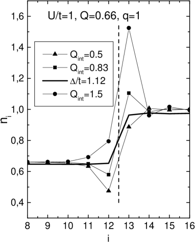
We begin by looking to the effect of the charge of the interface plane on the electron charge distribution. We find that the charge distribution is almost insensitive to the magnetic alignment of the FF layers. However, an important charge transfer occurs in the planes very near to the interface FF / PM. In Fig. 2 we show as a function of for , , , and three different values of . Not surprisingly the average electron charge of the nearest planes follows the excess or defect of charge of the interface plane, however the charge of the first separator plane exceeds its mean value () by 10% at average and can go up or down according to . On the contrary, the charge at the first FF layer is lower than while one would expect that the charge would accumulate on both sides of the interface. This seemingly surprising result is a consequence of the fact that each site at the separator can be doubly occupied while the FF sites can be only singly occupied. Since many of the FF are manganites and they are extremely sensitive to the average charge this fact could affect strongly the magnetic properties of the interface. Here we assume that all atomic planes at the FF are fully polarized. The effects of charge inhomogeneity in the FF planes will be reported in a different publication.
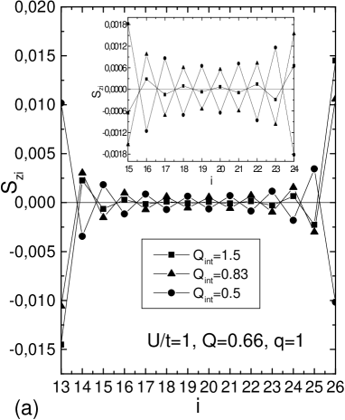
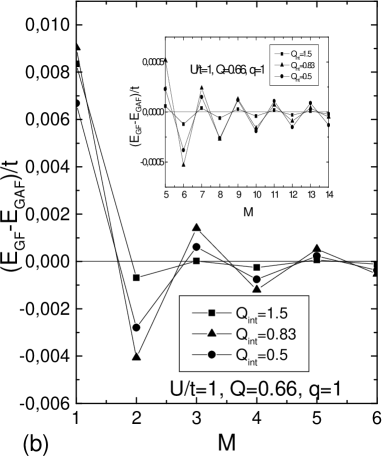
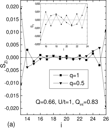
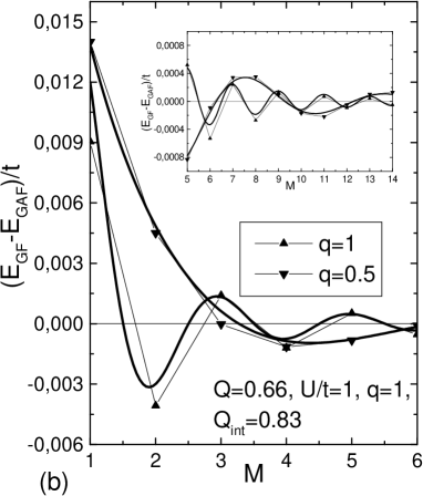
In this paper we focus on the CT effects on the separator (planes to ). To study the magnetization in these planes we define first the magnetic polarization at each PM plane. We show the effect of on the magnetization inside the PM displaying as function of for the antiferromagnetic arrangements (Fig. 3(a)) of the FF layers. We observe that the amplitude of the oscillations of at the interface increases with while the opposite occurs far from the interface, a change of sign of occurs for different values of as one can observe in Fig. 3(a). For F or AF alignments we calculate the ground state energies EGF and EGAF respectively for each value of . The resulting exchange coupling - as a function of is shown in Fig. 3(b). The period of oscillations of and can be identified with the extremal spanning vectors of the Fermi surface of the spacer (). This is shown in Fig. 4(a) and (b), where one can observe that changing and consequently the Fermi energy changes the period of oscillations accordingly. In Fig. 4(b) the continuous line corresponds to the first term in the stationary phase approximation (SPA) [3]. The SPA first term has the form , where and are parameters that we choose to fit the numerical results in Fig. 4(b) and (c). Note that far from the interface the SPA reproduces quite well the numerical results (see inset). In Fig. 4(c) we plot ( - as a function of for and and compare with the SPA approximation. We adjust and so as to fit the first point of the numerical result (). It can be seen that the later attenuate rapidly with much faster than the SPA result. This strong attenuation has been found in La0.66Ba0.34MnO3-LaNiO3-La0.66Ba0.34MnO3 trilayers by Nikolaev et al. in Ref. [8] and attributed to damping caused by strong electron scattering in the non-magnetic layer.

4 DISCUSSION AND CONCLUSION
We have presented a simple four parameter model to describe the coupling between two magnetic half metallic perovskites (as for example La1-xSrxMnO3.) separated by a metallic one (LaNiO3). The coupling is strongly affected by the charge transfer at the interface due to the different effect of the Coulomb interaction in the two materials. Recent two orbital calculations by Ohsawa et al.[15] using a potential difference to distinguish between manganite and spacer do not show these effects. For example in Fig.2 the broad line indicates the charge values at each atomic plane obtained using simply a potential difference adjusted to reproduce the values of and (potential difference . We can see that the result is a monotonous increase at the left interface from 0.66 to 1 and the opposite at the right interface.
Of the four parameters, only is not determined by the materials characteristics: controls the number of electrons in the manganites, charge at the interface, is a parameter that represents the possible differences between bulk and interface, ( in this calculation) controls the number of electrons in the separator. The single free parameter , is hard to estimate: it contributes to the Coulomb interaction as the sum of point charge interactions in the lattice. This would be a good approximation if the charge distribution were punctual or if there were no overlap between charges. This is far from reality, an ab-initio of the effective charges filling the atomic basin according to Bader’s theory gives significantly smaller values than the ideal ionic value. Hybridization with the nearest oxygen ions affects strongly the space charge distribution in non overlapping volumes. This reduces significantly the values of The ab-initio calculations were performed using the full-potential linearized/augmented plane wave plus local orbital (L/APW+lo) method, as implemented in the WIEN2K code[16, 17, 18]. The exchange-correlation effects were treated within the GGA (generalized gradient approximation) using the Perdew-Burke-Ernzerhof form [19]. For the calculation of charges, we used the Bader’s definition of atomic basins[20] calculated with the electronic densities obtained from the ab-initio calculations. The atomic basins were calculated with the total electronic density and then used to integrate the number of up and down electrons assigned to each atom.
In table I we show the results for two cases: LaMnO3 in the A-type antiferromagnetic phase, and CaMnO3 in a cubic G-type antiferromagnetic phase. While in CaMnO3 all oxygen atoms are equivalent (O1 in table I), in LaMnO3 there are two inequivalent oxygen atoms: the atoms within each ferromagnetic plane (O1) and the atoms located between two opposite ferromagnetic planes(O2).
| LaMnO3 | CaMnO3 | |||
|---|---|---|---|---|
| Charge | MM | Charge | MM | |
| La/Ca | 2.08 | 0.00 | 1.66 | 0.00 |
| Mn | 1.66 | 3.53 | 1.81 | 2.92 |
| O1 | -1.25 | 0.11 | -1.15 | 0.00 |
| O2 | -1.24 | 0.00 | - | - |
The results presented in table I indicate that the charge transfered by substitution of La by Ca is transfered not only to Mn as one purely ionic picture would indicate but it is transfered evenly to Mn and O. This is a consequence of the strong covalent bond tetween the transition metal and Oxigen. This result agrees with the conclusions obtained by Raebiger et al. reported in NATURE[21] and extends their results to perovskites. Another factor that reduces is screening. We have also modified the calculation including a term in the interaction, and used different values of which is also difficult to estimate in the ionic perovskites. We do not include here a study of the relaxation of the interface plane which could enhance the charge effects at the interface. We have also estimated the corrections due to different hopping magnitude for the spacer and found that these corrections do not produce qualitative changes in the results.
A quantitative calculation describing these type of interfaces is still far from reach. It should include at least a two orbitals description of the electronic structure as well as the effects of strain and defects at the interface. We believe that our study of the effect of coulomb interactions contributes to the understanding of some qualitative aspects of their properties.
In conclusion, we have shown the charge transfer at the interface between a half metallic and a metallic oxide is quite anomalous due to the ionic nature of the materials under study. These anomalies transfer to the different properties of the layered structures, as for example conductance trough the layers, magnetization in the spacer and magnetic coupling between the ferromagnetic layers. We have analyzed here the magnetic exchange in a trilayer formed by two half metals spaced by a metal.
Acknowledgments
B. A., J. D. F., and R. A. are supported by the Consejo Nacional de Investigaciones Científicas y Técnicas (CONICET).
References
- [1] M. N. Baibich et al., Phys. Rev. Lett., 61, 2472 (1988).
- [2] D.M. Edwards,J. Mathon,R.B.Muniz, and M.S. Phan, Phys. Rev. Lett., 67, 493 (1991);J. Magn. Magn. Mater. 93, 85 (1991).
- [3] J. Mathon et al., Phys. Rev. B, 56, 11797 (1997).
- [4] P. Bruno, Phys. Rev. B, 411, 52 (1995).
- [5] I. I. Oleynik and E. Y. Tsymbal, Interface Science 12, 105 (2004).
- [6] R. vonHelmolt,J. Wecker, B. Holzapfel, L. Schultz, and K. Samwer, Phys. Rev. Lett. 71, 2331 (1993).
- [7] P. Schlottmann, Phys. Rev. B, 73, 214428 (2006).
- [8] K. R. Nikolaev et al., Phys. Rev. Lett., 85, 3728 (2000).
- [9] M. Granada et al., Appl. Phys. Lett., 91, 72110 (2007).
- [10] L. P. Gor‘kov and V. Kresin, Phys. Reports., 400, 149 (2004).
- [11] Satoshi Okamoto and Andrew J. Millis, Phys. Rev. B, 70, 075101 (2004).
- [12] L. Brey, Phys. Rev. B, 75, 104423 (2007).
- [13] R. Allub and B. Alascio, Phys. Rev. B, 55, 14113 (1997); N. Pavlenko and T. Kopp, Phys. Rev. Lett., 97, 187001 (2006); S. Okamoto Andrew J. Millis, Phys. Rev. B, 70, 241104(R) (2004).
- [14] M. Granada et al., Physica B, 384, 68 (2006); M. L. Medarde, J. Phys. Condens. Matter 9, 1678 (1997).
- [15] T. Ohsawa,S. Kubota,H. Itoh, and J. Inoue, Phys. Rev. B, 71, 212407 (2005).
- [16] P. Blaha, K. Schwarz, G.K.H. Madsen, D. Kvasnicka, J. Luitz, “WIEN2k, An Augmented Plane Wave + Local Orbitals Program for Calculating Crystal Properties”, (Karlheinz Schwarz, T.U. Wien, Austria, 2001): ISBN 3-9501031-1-2.
- [17] K. Schwarz, P. Blaha, and G. K. H. Madsen, Comput. Phys. Commun. 147, 71 (2002).
- [18] K. Schwarz and P. Blaha, Comput. Mater. Sci. 28, 259 (2003).
- [19] J.P. Perdew, S. Burke, M. Ernzerhof, Phys. Lett. 77, 3865 (1996).
- [20] R.F.W. Bader, “Atoms in Molecules”, Oxford University Press, Oxford (1995).
- [21] Raebiger et al., NATURE 435, 763 (2008).