Molecular rolling friction: the cogwheel model
Abstract
With the help of a two-dimensional model we study rolling lubrication by circular (“2D fullerenes”) molecules for a wide range of parameters. The conditions under which microscopic rolling friction may be effective are identified, and related to the relative ingraining between substrate and molecule, the latter behaving as a nanosized cogwheel.
pacs:
68.35.Af, 81.40.Pq, 61.48.+c, 68.60.-pKeywords: molecular rolling friction; fullerenes
1 Introduction
Feynman [1] famously foreshadowed atomic-scale machines that could perform similarly to their macroscopic analogs. Nowadays the problem of designing nanomechanical devices, in particular, to reduce friction by means of nano- and micro-bearings [2] is real. The possible use of fullerene C60 for molecular nanobearings gave rise to Molecular Dynamics (MD) modeling [3, 4, 5, 6]. Other fullerene-like metal dichalcogenide MX2 (where M=Mo or W and X=S or Se) molecules were considered as additives in oil lubricants, and predicted to provide interesting tribological properties (e.g., see [7] and references therein). Simulations showed that ball-shaped molecules may either slide or rotate over a surface, depending on the substrate and the position of the molecule. For example, C60 slides on graphite in the AB configuration (hexagonal C60 ring lying flat on graphite), but rotates in the on-top frustrated AB configuration where one C60 corner atom faces the center of the graphite hexagon. The rolling configuration is characterized by very low friction [3, 5], with a predicted friction coefficient of the order [4] or even smaller [5].
Attempts to realize these ideas experimentally had only limited success so far. A single C60 molecule confined between two solid substrates may begin to roll when a torque of order Nm is applied [8]. However, C60 molecules actually condense to form close-packed layers, as found, e.g., on a graphite substrate [9, 10]. A single C60 monolayer (ML) takes a crystalline structure with 2D spatial order at low temperatures. It undergoes a first-order orientational order-disorder transition at K [11], the molecules exhibiting free rotation at . At there is an abrupt change in friction [12], but the lowest friction coefficient is of order [10, 12], worse than with traditional oil-based lubricants. Coffey and Krim [13] reported a quartz crystal microbalance study of one or two C60 monolayers adsorbed on Ag(111) or Cu(111). There are no rotations in a C60 ML on Cu(111), and only a slow change of molecular orientations in the C60/Ag(111) ML. For two ML instead, C60 molecules in the second layer rotate freely at 300 K. However a molecularly thin methanol film deposited over the C60, failed to show either the expected low friction, or any essential difference between these systems. Thus this particular nanobearing design apparently would not work.
Some charge transfer and bonding between C60 and the metal substrate may be held responsible for hindering the rolling. Another reason lies in the full layer coverage. Balls in macroscopic bearings are arranged so as to prevent contact, but rolling molecules in the ML are always in contact, hindering their mutual rolling and jamming the same way two ingrained rolling cogwheels would. As discussed earlier on [14], a way to avoid jamming is to lower dramatically the coverage, well below one ML (the molecule density should anyway be sufficient to prevent the two surfaces from touching). In view of that, and in the lack of well defined low coverage experiments, a study of the single molecule rolling friction represents a natural starting point, and indeed a revealing one.
Macroscopically, the main source of rolling friction of a ball or tire comes from deformation. Both substrate and roller are (elastically or plastically) deformed at the contact. The deformation energy is partly released and lost as bulk frictional heat when the roller moves on [15]. By designing the bulk so that dissipation is poor, rolling friction can be made to times lower than the sliding friction; the latter being due to adhesion, i.e., breaking and re-forming of slider-substrate bonds. It the previous work [14] we studied molecular rolling friction for the system, where the lubricant and both substrates were constructed of the same molecules, so that the lubricant and substrates were deformable and commensurate. The minimal friction coefficient found in simulation, was of order in agreement with available experimental data. Naturally it emerges a question, what would be a value of for the rigid substrates, when the losses due to deformation are absent, or for the case of incommensurate lubricant/substrate interface. As the roller size is decreased however, adhesion grows in importance, eventually becoming the main source of friction. To rotate a molecule, one has to break the molecule-substrate bonds from one side of the molecule and create new bonds on the opposite side. Thus, there are no reasons to expect that molecular rolling friction should be much lower than the sliding friction.
Our present goal is to understand what could be the lowest friction coefficient attainable for molecular rolling and which system parameters might provide it. Besides, we show that a macro- to microworld mapping does work, but one has to choose properly the macroscopic counterpart, which in the present case is a cogwheel. Because we are interested in general trends, we explore a minimal two-dimensional (2D) model, which allows us to span a large number of parameters, and also provides an easier visualization of the processes inside the lubricant.
2 Model
We consider two substrates with lubricant molecules in between, all of them made up of classical point particles (atoms). Atoms can move in the plane, where is the sliding direction and is perpendicular to the substrates. The substrates, pressed together by a load force , consist of rigid atomic chains of length and equal lattice constant , so that the system size in the sliding direction is and the total mass of the substrate is (we use periodic boundary condition along ). The bottom rigid substrate is fixed at , the top one is free to move in both and . The top substrate is driven along with speed through a spring of elastic constant . The spring force , whose maximum value before motion measures the static friction force , and whose average during smooth motion is the kinetic friction force, is monitored during simulation (throughout the paper we normalize forces per substrate atom ). Thus, our model is a 2D variant of a typical experimental setup in tribology [15, 16]. Between the substrates we have circular (“spherical”) lubricant molecules built as in Ref. [14]. Each molecule has one central atom and atoms on circle of radius so that their chord distance is . They are coupled with the central atom, additionally to the 12-6 Lennard-Jones (LJ) potential, by stiff springs of elastic constant , , where the distance is chosen so that the total potential is minimum at . With the resulting stiff molecular shape resisted destruction during the simulations. All atoms interact via the LJ potential , where or for the substrate or lubricant atoms respectively. Thus, the lubricant-lubricant interaction is described by the parameters and , while the lubricant-substrate interaction, by and (direct interaction between the top and bottom substrates is omitted, as they are not allowed to touch). We use dimensionless units, where , , and the energy parameters takes values around .
Because a 2D model cannot reproduce even qualitatively the phonon spectrum of a 3D system, and because frictional kinetics is generally diffusional rather than inertial, we use Langevin equations of motion with Gaussian random forces corresponding to temperature , and a damping force , where are the atomic coordinates and are the coordinates of the top substrate (the force is defined in the same way). The viscous damping coefficient is assumed to decrease with the distance from the corresponding substrate, , where typically and .
We present simulation results for molecule friction from (the simplest circular molecule) up to and 14, which may be considered as a 2D version of fullerenes. In fact in the 3D case, the surface area of the spherical molecule is . If we put atoms on the surface, this gives , or . In 2D, the length of the circle is , or , which leads to for the same ratio as for 3D fullerenes.
3 Rigid molecule
We first consider a rigid circular molecule, i.e., and . Let us fix of the top substrate and seek minimum of the potential energy by varying the coordinate of the top substrate, and the center and the rotation angle of the molecule. The dependence of , , and defines the adiabatic trajectory, which describes the joint substrate and lubricant motion when infinitely slow. We define the activation energy , and the magnitude of the static friction force, approximated as ( in our units).

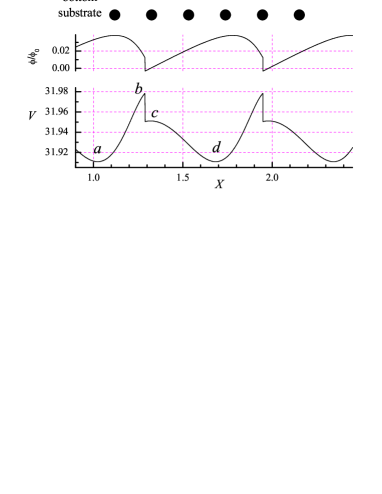
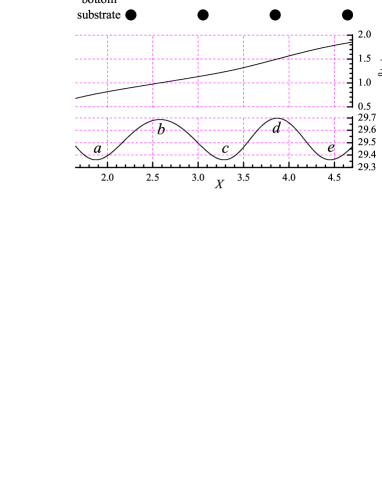
Figures 1 and 2 show the results for the molecule when, to simplify further, is kept constant, . The energy is periodic with (or a multiplier of ). The molecular angle varies by as the potential energy changes from minimum to maximum. Because must be continuous, the motion corresponds to sliding if , while if the molecule must rotate when it moves. As figure 1 shows, for the motion corresponds to sliding, i.e., the molecule is shifted as a whole, slightly oscillating during motion (figure 2, left panel). Similarly to the motion of a dimer in a periodic potential [17], the activation energy has maxima at (where is an integer) and minima at . On the other hand, for the motion corresponds to rolling (figure 2, right panel). Here has minima at some values of the ratio (e.g., for in figure 1).
Varying in figure 1, we kept fixed the equilibrium distance for the lubricant-substrate interaction. More realistically, it might be reasonable to set, e.g., , in which case, as we observed, the interval of values where rolling prevails is wider than for fixed . Further preference for rolling over sliding is found for increasing load and for decreasing interaction strength . We also note that when sliding wins over rolling for , it provides a lower activation energy. Recalling that , the region of parameters for rolling should increase with – a rounder wheel rolls better. The dependence of for increasing size (figure 3) shows rolling for all and for all , except for which shows both rolling and sliding (see open symbols in figure 3a). As varies, the value of changes by more than two orders of magnitude for even and more than three for odd , with deep sharp minima separated by broad maxima. Clearly, by suitably choosing a very strong decrease of rolling friction is attainable.


The deep minima of are explained by simple engineering – a “cogwheel model”. Consider the molecule as a cogwheel with cogs, primitive radius and external radius , where . The chord distance between nearest cogs is . Best rolling conditions are expected when matches the substrate potential period , i.e., for and its fractions, , , etc. The main minimum of is expected at
| (1) |
As shown in figure 4, the cogwheel model (1) with , where is a parameter, can fit very well the shift of minimum position with molecular size . It can explain its variation with load (the radius and therefore decrease as the load grows) as well as with the lubricant-substrate interaction ( and decrease with ). It also accounts for the even-odd effect since odd involves ingraining perfectly one substrate at a time, justifying why roughly double values of are needed for even relative to odd .

4 MD simulation
The simulation results for the static friction of a deformable circular molecule are presented in figure 5.

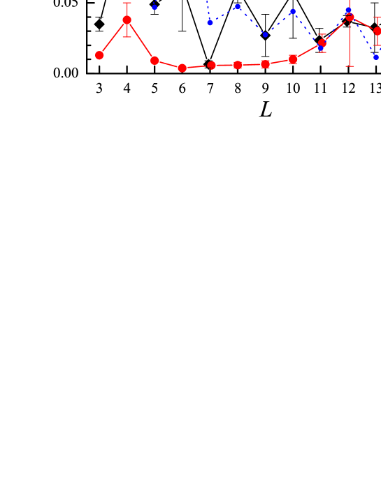
As one could expect, the or 4 “circular” molecule does not roll; instead we observed its “creep” with a relatively large friction. For larger values of , , the molecule may either roll or slide. For rolling in the case of even values of ( and 14) one needs to break simultaneously two lubricant-substrate bonds (one connecting the lubricant molecule with the bottom substrate, and one, with the top substrate). Therefore, should be approximately independent of , as indeed is observed in simulation for . For odd values of , and 15, is at least two times smaller than for a nearest even value, because one needs to break one bond only at a time. For all the static friction is relatively low, , and for large odd values the friction may reach quite low values.
The results obtained for the rigid molecules in section 3, are qualitatively confirmed by the static friction force obtained from simulation with deformable molecules. Figure 6 compares the results obtained for the rigid molecule with the MD calculation of the static friction force of the deformable molecule. The agreement between these two dependences is reasonable, at least qualitatively.


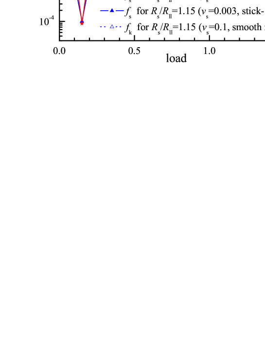
The friction coefficient ranges from at to or even at . These results are robust to a change of model parameters. For example, figure 7 compares the dependences for two values of the amplitude of lubricant-substrate interaction, and , and for two values of the load, and .

The next two figures show the dependence of the static and kinetic friction on (figure 8) and on the load (figure 9); the latter demonstrates that the friction force approximately follows the Amontons law
| (2) |
Visualization of MD trajectories shows that for , where friction is high, rolling rotation is accompanied by a molecular shift/sliding, – much as cogwheels with excessive clearance would do – while for , where friction is low, the motion corresponds to pure rotation, corresponding to optimal cogwheel coupling.
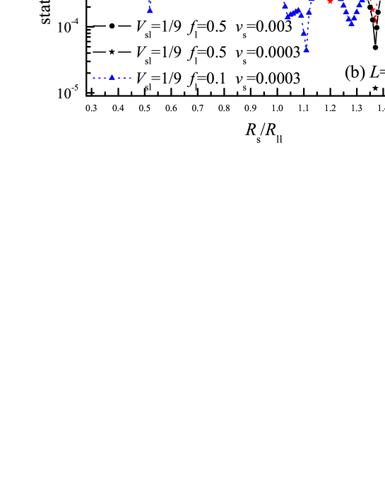
Simulations showed that the results presented above remain valid at nonzero temperature . When increases, we observed both static and kinetic friction force to decrease, the stick-slip changing to creep and finally to smooth motion at a high temperature.
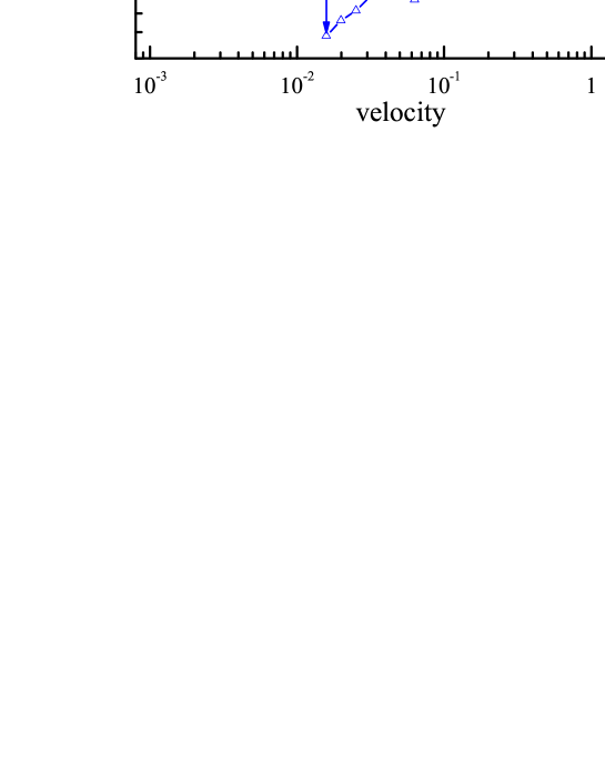
Moreover, we found a transition from stick-slip to smooth rolling for increasing velocity (figure 10). The cogwheel effect remains, and for example calculated static friction for and still differ by a factor of 10 or more. The critical velocity of the transition from stick-slip to smooth rolling also differs by a factor of about four in the two cases. Moreover we always find .
The present approach to the single rolling molecule can be extended to a finite coverage of lubricant molecules.
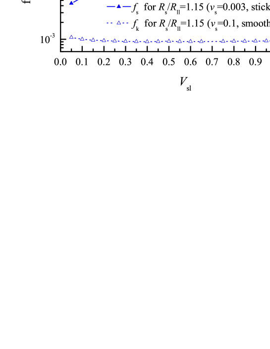
For example, figure 11 shows the friction force for a finite concentration of lubricant molecules, which may be compared with those of figure 5 for a single molecule. These results are for approximately the same load per one lubricant molecule ( in both cases), and we used a relatively low concentration of lubricant molecules, , to avoid jams. The dependence in figure 11 is essentially similar to that of figure 5, although the even-odd oscillation of with are less pronounced at the finite concentration because of collisions between the molecules. As for kinetic friction at high driving velocity for smooth motion, it demonstrates a more monotonic behavior with without even-odd oscillations. The function reaches a minimum at where , and then increases until ; at higher values of the dependence approximately repeats the behavior of .

Finally, figure 12 shows the dependence of the friction force on the concentration of lubricant molecules for and , which provided a low friction in the single molecule case (figure 7a). When increases, the total loading force is split over the molecules, so that for a given molecule the load is . As the load decreases with , the friction force per molecule should also decrease according to (2). At the same time, the total friction force should increase, . A combined effect is a slow increase of the friction with as shown in figure 12 with dotted curve and open symbols. In a real situation, coalescence may lead to jamming, with molecules blocking their mutual rotation [14]. In our model, jamming starts already at and completely destroys rolling at (here is the coverage, with the number of molecules in the monolayer).
5 Conclusion
Summarizing, we can extract from our 2D model the following conclusions. Rolling spherical lubricant molecules can indeed provide better tribological parameters than sliding atomic lubricants. The effect may be as large as in macroscopic friction, where rolling reduces friction by a factor of , however only for sufficiently low coverage of lubricant molecules, and for specially chosen values of the ratio , corresponding to perfect cogwheel rolling. To check experimentally these predictions, it would be interesting to study friction coefficient for different spherical molecules, different coverages, and different substrates. Also, the relative ingraining between the rolling molecule and the substrate may be improved by adjusting the applied load, as it was demonstrated experimentally for the molecular rack-and-pinion device [18]. Inert nonmetal surface (such as perhaps self-assembled monolayers) may represent a better choice of substrate than metals for fullerenes deposition. Because 3D rolling has an azimuthal degree of freedom, the cogwheel effect described should be direction dependent, and rolling friction should exhibit anisotropy depending on direction.
References
References
- [1] Feynman R P 1960 Eng. Sci. 23 22
- [2] Drexler K E 1992 Nanosystems: Molecular Machinery, Manufacturing, and Computation (New York, Wiley)
- [3] Legoas S B, Giro R and Galvão D.S 2004 Chem. Phys. Lett. 386 425
- [4] Kang J W and Hwang H J 2004 Nanotechnology 15 614
- [5] Sasaki N, Itamura N, Tsuda D and Miura K 2007 Current Nanoscience 3 105
- [6] Keeling D L, Humphry M J, Fawcett R H J, Beton P H, Hobbs C and Kantorovich L 2005 Phys. Rev. Lett. 94 146104
- [7] Greenberg R, Halperin G, Etsion I and Tenne R 2004 Tribol. Lett. 17 179
- [8] Miura K, Kamiya S and Sasaki N 2003 Phys. Rev. Lett. 90 55509
- [9] Blau P J and Haberlin C E 1992 Thin Solid Films 219 129; Bhushan B, Gupta B K, Cleef Van G W, Capp C, Coe J V 1993 Appl. Phys. Lett. 62 3253; Thundat T, Warmack R J, Ding D, Compton R N 1993 Appl. Phys. Lett. 63 891; Schwarz U D, Allers W, Gensterblum G, Wiesendanger R 1995 Phys. Rev. B 52 14976
- [10] Mate C M 1993 Wear 168 17; Luengo G, et al., 1997 Chem. Mater. 9 1166; Okita S, Ishikawa M and Miura K 1999 Surf. Sci. 442 L959; Nakagawa H, Kibi S, Tagawa M, Umeno M, Ohmae N 2000 Wear 238 45
- [11] Heiney P A, Fischer J E, McGhie A R, Romanow W J, Denenstein A M, McCauley Jr. J P and Smith A B 1991 Phys. Rev. Lett. 66 2911; Johnson R D, Yannoni C S, Dorn H C, Salem J R, Bethune D S 1992 Science 255 1235; David W I F, Ibberson R M, Dennis T J S, Hare J P, Prassides K 1992 Europhys. Lett. 18 219
- [12] Liang Qi, Tsui O K C, Xu Y, Li H and Xiao X 2003 Phys. Rev. Lett. 90 146102
- [13] Coffey T and Krim J 2006 Phys. Rev. Lett. 96 186104
- [14] Braun O M 2005 Phys. Rev. Lett. 95 126104
- [15] Persson B N J 1998 Sliding Friction: Physical Principles and Applications (Springer-Verlag, Berlin)
- [16] Braun O M and Naumovets A G 2006 Surf. Sci. Reports 60 79
- [17] Braun O M 1990 Surface Sci. 230 262
- [18] Chiaravalloti F, Gross L, Rieder K-H, Stojkovic S M, Gourdon A, Joachim C and Moresco F 2007 Nature Materials 6 30