Rotational stabilization and destabilization of an optical cavity
Abstract
We investigate the effects of rotation about the axis of an astigmatic two-mirror cavity on its optical properties. This simple geometry is the first example of an optical system that can be destabilized and, more surprisingly, stabilized by rotation. As such, it has some similarity with both the Paul trap and the gyroscope. We illustrate the effects of rotational (de)stabilization of a cavity in terms of the spatial structure and orbital angular momentum of its modes.
Instability is ubiquitous in physics. Examples range from the simple case of a particle on the top of a hill to complex weather systems. Some partially unstable systems can be stabilized by external motion. One of the best-known examples of dynamical stabilization is the Paul trap Paul and Steinwedel (1953), which is similar to rotational stabilization of a particle in a saddle-point potential Thompson et al. (2002). Another well-known example of rotational stabilization is the gyroscope. Similar behavior has also been observed in thermodynamically large systems such as granular matter Zik et al. (1994) and fluids Salhi and Cambon (2007).
In recent years, optical cavities with moving elements have become topical. State-of-the-art experiments focus on optomechanical oscillators driven by radiation pressure Kippenberg et al. (2005); Corbitt et al. (2006) and cavity-assisted trapping and cooling Cohadon et al. (1999); Kleckner and Bouwmeester (2006); Gröblacher et al. (2008). Possible applications range from weak-force detection Lucamarini et al. (2006) to fundamental research on quantum entanglement Vitali et al. (2007); Bhattacharya et al. (2008) and decoherence Bernad et al. (2006); Kleckner et al. (2008) on macroscopic scales. In addition to the longitudinal radiation pressure, electromagnetic fields can exert transverse forces on small particles due to their phase structure Roichman et al. (2008). A specific example is the transfer of optical orbital angular momentum Molina-Terriza et al. (2007), which can can give rise to a torque along the propagation axis of the beam. Recently, it was shown theoretically that this torque can be sufficiently large to trap and cool the rotational degrees of freedom of a mirror in a cavity-assisted setup Bhattacharya and Meystre (2007). Here, we focus on the complementary question: How does rotation of a mirror affect the optical properties of a cavity and, in particular, its (in)stability? As such, this work constitutes the first analysis of rotational effects on stability in optics.
We consider a cavity that consists of two mirrors facing each other. In the simplest case both mirrors are spherical. Depending on their focussing properties, a ray that is coupled into such a cavity can either be captured, or escape after a finite (and typically small) number of round trips. In the latter case the cavity is geometrically unstable whereas it is stable in the first. The stability criterion for this system can be expressed as Siegman (1986)
| (1) |
where with the radii of curvature of the two mirrors and their separation. The optical properties of unstable cavities are essentially different from those of their stable counterparts Siegman (1986). The modes of a stable cavity are stationary and spatially confined whereas the ’modes’ of an unstable cavity are self-similar diverging patterns that have a fractal nature Karman et al. (1999). Instability is a necessary condition for an optical cavity to display chaotic behavior Puentes et al. (2004).
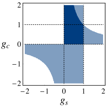
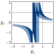
We consider rotations about the optical axis of a cavity and expect an effect only if at least one of the mirrors is astigmatic (or cylindrical), so that the cavity lacks axial symmetry. In general, both mirrors can be astigmatic with non-parallel axes but, for simplicity, we focus on a cavity that consists of a cylindrical () and a spherical () mirror. The curvature of each mirror can be specified by a single parameter so that the configuration space, spanned by and , is two dimensional. In the absence of rotation the stability criterion in the plane through the optical axis in which the cylindrical mirror is curved is of the form of Eq. (1): . In the other, perpendicular plane through the cavity axis, in which the cylindrical mirror is flat, the stability criterion reads: . As is indicated in the upper left plot of Fig. 1, stable (dark) areas appear where both criteria are met. The cavity is partially stable (light) in areas where only one of the two is fulfilled. When the cavity is partially stable, both a ray that is coupled into it and its modes are confined in one of the two transverse directions only. One may guess that rotation disturbs the confinement of the light by the mirrors so that all (partially) stable cavities will eventually lose stability if the rotation frequency is sufficiently increased. However, we will show that this is not the case.

In order to describe the diffraction of the light inside the rotating cavity, we use the paraxial approximation and its generalization to the time-dependent case Lax et al. (1975); Deutsch and Garrison (1991). We write the transverse electric field of a propagating mode as
| (2) |
where is the amplitude of the field, is the polarization, is the wave number and is the optical frequency with the speed of light. The large-scale spatial structure and slow temporal variations of the electric field are characterized by the complex scalar profile . In lowest order of the paraxial approximation and under the assumption that the time dependence of the profile is slow compared to the optical time scale, the electric field is purely transverse and the profile obeys the time-dependent paraxial wave equation
| (3) |
with . If we omit the derivative with respect to time, this equation reduces to the standard paraxial wave equation, which describes the diffraction of a freely propagating stationary paraxial beam. The additional time derivative accounts for the time dependence of the profile and incorporates retardation between distant transverse planes.
The dynamics of light inside a cavity is governed by the boundary condition that the electric field vanish on the mirror surfaces. For a rotating cavity, this boundary condition is explicitly time dependent. This time dependence vanishes in a corotating frame where it is sufficient to consider time-independent propagating modes . The transformation that connects and takes the form
| (4) |
where is the rotation frequency and is the operator that rotates a scalar function over an angle about the axis with the component of the orbital angular momentum operator. Substitution of the rotating mode (4) in the time-dependent wave equation (3) gives
| (5) |
for . The transformation to a rotating frame gives rise to a Coriolis term, in analogy with particle mechanics. Since and commute, the formal solution of Eq. (5) can be expressed as
| (6) |
where and is the unitary operator that describes free propagation of a paraxial beam in a stationary frame. The operator has the significance of the propagator in the rotating frame. The rotation operator arises from the Coriolis term in Eq. (5) and gives the propagating modes a twisted nature.
The transformation of paraxial modes under propagation and optical elements can be expressed in terms of a ray () matrix Siegman (1986). The standard ray matrices that describe optical elements with axial symmetry can be found in any textbook on optics. The ray matrix of a composite system can be constructed by multiplying the ray matrices that describe the optical elements and the distances of free propagation between them, in the proper order. Generalization to astigmatic optical elements is straightforward and requires ray matrices Siegman (1986); Habraken and Nienhuis (2007). The ray matrix that describes propagation in a rotating frame is, analogous to Eq. (6), given by , where is the ray matrix that describes free propagation over a distance and is the ray matrix that rotates the position and propagation direction of a ray over an angle about the axis. Starting at the entrance plane of the spherical mirror, the time-independent ray matrix that describes a round trip through the rotating cavity in the corotating frame is then
| (7) |
where is the mirror separation and and are the ray matrices for the spherical and the cylindrical mirror. They are fully determined by the radii of curvature and the orientation of the mirrors in the transverse plane Habraken and Nienhuis (2007).
Typically, the round-trip ray matrix (7) has four distinct time-independent eigenvectors with corresponding eigenvalues . In the rotating frame, any time-dependent incident ray can be expanded as . After times bouncing back and forth between the mirrors, the ray evolves into . The possibly complex eigenvalues have the significance of the magnification of the eigenvector after one round trip and it follows that a cavity is stable only if all four eigenvalues have absolute value 1. The eigenvalues of any physical ray matrix come in pairs and Habraken and Nienhuis (2007) so that deviations from appear in two of the four eigenvalues at the same time. If only two eigenvalues have absolute value 1, the cavity is partially stable. The eigenvalues of the round-trip ray matrix (7) do not depend on the frame of reference, and it follows that the same is true for the notion of stability.
A ray that is bounced back and forth inside the cavity hits a mirror at time intervals . Since a rotation over turns an astigmatic mirror to an equivalent orientation, it follows that the stability of a cavity is not affected by a change in the rotating frequency with integer and . In the present case, in which one of the mirrors is spherical, a ray hits the cylindrical mirror at time intervals so that the eigenvalues are periodic with . Moreover, an astigmatic cavity is not gyrotropic so that the eigenvalues do not depend on the sign of . It follows that it is sufficient to only consider rotation frequencies in the range .
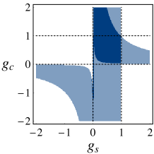
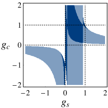
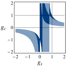
By using the expression of the ray matrix in the corotating frame (7) and the stability criterion that its eigenvalues must have a unit length, we find the stable, partially stable and unstable sections in the configuration space for different values of the rotation frequency. The results are shown in Fig. 1. These plots reveal that, already at relatively small rotation frequencies, quite drastic changes take place. For instance, near stable configurations are destabilized to become (partially) unstable, while partially stable geometries near the negative axis are stabilized by the rotation. An optical cavity can thus both lose and gain the ability to confine light due to the fact that it rotates. It is noteworthy that some configurations, for example those with small and positive and , are first partially destabilized by rotation, but retrieve stability if the rotation frequency is further increased. Another remarkable feature of the plots in Fig. 1 is the absence of partially stable areas in the lower right plot. As we will argue below, this is more generally true for the rotation frequency . In this specific case, the boundaries of stability are given by the hyperbolas and and their asymptotes.
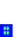
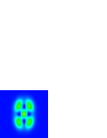
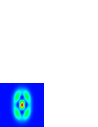
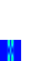
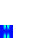
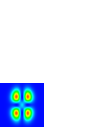
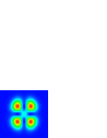
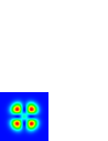
As we have recently shown Habraken and Nienhuis (2008), the structure of the modes of a rotating cavity is fully determined by the eigenvectors . The modes are defined as corotating solutions of the time-dependent paraxial wave equation (3) that vanish on the mirror surfaces. Geometric stability comes in as the necessary and sufficient requirement for them to exist. Here, we illustrate the effect of rotational (de)stabilization on the mode structure by considering two cases of a cavity with a spherical and a cylindrical mirror. Cavity I is specified by . It is stable in the absence of rotation and destabilized at a rotation frequency . Cavity II is specified by the parameter values . It is partially stable in the absence of rotation and stabilized by rotation at . The effect of rotation on the spatial structure of the modes of cavities I and II is shown in Fig. 2. The upper frames show the transverse spatial structure on the spherical mirror of the mode of cavity I. From left to right the rotation frequency increases from to in equal steps. In the absence of rotation (left frame) the mode is an astigmatic Hermite-Gaussian mode. Due to rotation, the mode is deformed to a generalized Gaussian mode with a nature in between Hermite-Gaussian and Laguerre-Gaussian modes Abramochkin and Volostnikov (2004). As a result, phase singularities or so-called optical vortices Soskin and Vasnetsov (2001), which are visible as points with zero intensity, appear. For rotation frequencies close to , the mode loses its confinement in the vertical direction. This reflects the fact that the cavity approaches a region of partial instability. The lower frames in Fig. 2 show the intensity pattern on the spherical mirror of the mode of cavity II, which is stabilized by rotation. From left to right the rotation frequency is increased from to in equal steps. As a result of the rotation we retrieve a mode that is confined in both directions and is similar to a Hermite-Gaussian mode. Deformation of the mode due to the rotation is more pronounced for even larger values of the rotation frequency.
Obviously, the horizontal and vertical directions in Fig. 2, which correspond to the curved and flat directions of the cylindrical mirror, are lines of symmetry. In the special case of a rotation frequency , the cylindrical mirror is rotated over after each round trip so that its orientation is periodic with two round-trip times as a period. This causes the diagonal lines between the horizontal and vertical directions to be lines of symmetry of the round-trip ray matrix (7) and the intensity patterns. This explains the apparent absence of astigmatism in the lower right plot of Fig. 2. This additional symmetry also causes the four eigenvalues to have the same absolute value, which explains the absence of partial stability in the lower right plot of Fig. 1.
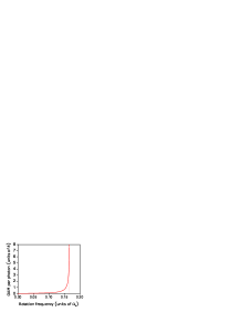
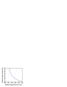
Though the intensity patterns of the modes are aligned along the axes of the cylindrical mirror, their phase patterns are not. These attain a twist that is a signature of orbital angular momentum Molina-Terriza et al. (2007); Visser and Nienhuis (2004), proportional to . The dependence of this orbital angular momentum in the mode of cavity I on the rotation frequency is shown in Fig. 3 (left plot). The orbital angular momentum shows a divergence at , which arises from the induced instability of the cavity. The opposite happens for cavity II (right plot), which is stabilized by rotation. In this case the orbital angular momentum decreases with increasing rotation frequencies and eventually vanishes for due to the additional symmetry at this specific rotation frequency. The vanishing orbital angular momentum does not imply that there is no vorticity in the modes at this rotation frequency. The two contributions to the orbital angular momentum add up to zero for modes with two equal mode numbers.
In this paper, we have investigated rotationally induced transitions between the areas of stability and partial instability of an astigmatic two-mirror cavity. This is the first example of an optical system where stability can be induced or removed by rotation. Mechanical systems with dynamical stabilization are the Paul trap and the gyroscope. The most obvious signatures of rotational (de)stabilization are the modification of the mode confinement and the divergence of the orbital angular momentum, respectively shown in Figs. 2 and 3. The spatial structure of these modes may be difficult to measure, but since their orbital angular momentum components appear at different frequencies due to the rotational Doppler shift Nienhuis (1996); Courtial et al. (1998), it is possible to resolve the divergence of the orbital angular momentum spectroscopically. The effects of transverse rotations on the optical properties of a cavity are significantly more complex than the resonance shifts that are associated with small longitudinal displacements of the mirrors. This may have important consequences in cavity-assisted optomechanical experiments in which the rotational degrees of freedom of a mirror are addressed.
Though the setup that we have studied here is rather specific, our method, which is exact in the paraxial limit, can be applied to more complex optical systems. Moreover, it should also be applicable to other, mathematically similar, wave-mechanical systems. Examples include the quantum-mechanical description of a particle in a rotating, partially stable potential and rotating acoustical cavities. In particular, the modification of the mode confinement and the rotationally induced angular momentum are expected to have analogues in such systems.
It is a pleasure to thank Eric R. Eliel and Bart-Jan Pors for fruitful discussions and valuable suggestions regarding this manuscript.
References
- Paul and Steinwedel (1953) W. Paul and H. Steinwedel, Z. Naturforsch. A 8, 448 (1953).
- Thompson et al. (2002) R. Thompson, T. Harmon, and M. Ball, Can. J. Phys. 80, 1433 (2002).
- Zik et al. (1994) O. Zik, D. Levine, S. G. Lipson, S. Shtrikman, and J. Stavans, Phys. Rev. Lett. 73, 644 (1994).
- Salhi and Cambon (2007) A. Salhi and C. Cambon, Phys. Rev. E 75, 016312 (2007).
- Kippenberg et al. (2005) T. J. Kippenberg, H. Rokhsari, T. Carmon, A. Scherer, and K. J. Vahala, Phys. Rev. Lett. 95, 033901 (2005).
- Corbitt et al. (2006) T. Corbitt, D. Ottaway, E. Innerhofer, J. Pelc, and N. Mavalvala, Phys. Rev. A 74, 021802(R) (2006).
- Cohadon et al. (1999) P. F. Cohadon, A. Heidmann, and M. Pinard, Phys. Rev. Lett. 83, 3174 (1999).
- Kleckner and Bouwmeester (2006) D. Kleckner and D. Bouwmeester, Nature (London) 444, 75 (2006).
- Gröblacher et al. (2008) S. Gröblacher, S. Gigan, H. R. Böhm, A. Zeilinger, and M. Aspelmeyer, Europhys. Lett. 81, 54003 (2008).
- Lucamarini et al. (2006) M. Lucamarini, D. Vitali, and P. Tombesi, Phys. Rev. A 74, 063816 (2006).
- Vitali et al. (2007) D. Vitali, S. Gigan, A. Ferreira, H. R. Böhm, P. Tombesi, A. Guerreiro, V. Vedral, A. Zeilinger, and M. Aspelmeyer, Phys. Rev. Lett. 98, 030405 (2007).
- Bhattacharya et al. (2008) M. Bhattacharya, P.-L. Giscard, and P. Meystre, Phys. Rev. A 77, 030303(R) (2008).
- Bernad et al. (2006) J. Z. Bernad, L. Diosi, and T. Geszti, Phys. Rev. Lett. 97, 250404 (2006).
- Kleckner et al. (2008) D. Kleckner, I. Pikovski, E. Jeffrey, L. Ament, E. Eliel, J. van den Brink, and D. Bouwmeester, e-print arXiv:0807.1834.
- Roichman et al. (2008) Y. Roichman, B. Sun, Y. Roichman, J. Amato-Grill, and D. G. Grier, Phys. Rev. Lett. 100, 013602 (2008).
- Molina-Terriza et al. (2007) G. Molina-Terriza, J. P. Torres, and L. Torner, Nature Physics 3, 305 (2007).
- Bhattacharya and Meystre (2007) M. Bhattacharya and P. Meystre, Phys. Rev. Lett. 99, 153603 (2007).
- Siegman (1986) A. E. Siegman, Lasers (University Science Books, Mill Valley, California, 1986).
- Karman et al. (1999) G. P. Karman, G. S. McDonald, G. H. C. New, and J. P. Woerdman, Nature (London) 402, 138 (1999).
- Puentes et al. (2004) G. Puentes, A. Aiello, and J. P. Woerdman, Opt. Lett. 29, 929 (2004).
- Lax et al. (1975) M. Lax, W. H. Louisell, and W. B. McKnight, Phys. Rev. A 11, 1365 (1975).
- Deutsch and Garrison (1991) I. H. Deutsch and J. C. Garrison, Phys. Rev. A 43, 2498 (1991).
- Habraken and Nienhuis (2007) S. J. M. Habraken and G. Nienhuis, Phys. Rev. A 75, 033819 (2007).
- Habraken and Nienhuis (2008) S. J. M. Habraken and G. Nienhuis, Phys. Rev. A 77, 053803 (2008).
- Abramochkin and Volostnikov (2004) E. G. Abramochkin and V. G. Volostnikov, J. Opt. A: Pure Appl. Opt 6, S157 (2004).
- Soskin and Vasnetsov (2001) M. S. Soskin and M. V. Vasnetsov, Prog. Opt. 42, 219 (2001).
- Visser and Nienhuis (2004) J. Visser and G. Nienhuis, Phys. Rev. A 70, 013809 (2004).
- Nienhuis (1996) G. Nienhuis, Opt. Commun. 132, 8 (1996).
- Courtial et al. (1998) J. Courtial, K. Dholakia, D. A. Robertson, L. Allen, and M. J. Padgett, Phys. Rev. Lett. 80, 3217 (1998).