Low frequency elastic wave propagation in 2D locally resonant phononic crystal with asymmetric resonator
Abstract
The resonance modes and the related effects to the transmission of elastic waves in a two dimensional phononic crystal formed by periodic arrangements of a two blocks unit cell in one direction are studied. The unit cell consists of two asymmetric elliptic cylinders coated with silicon rubber and embedded in a rigid matrix. The modes are obtained by the semi-analytic method in the least square collocation scheme and confirmed by the finite element method simulations. Two resonance modes, corresponding to the vibration of the cylinder along the long and short axes, give rise to resonance reflections of elastic waves. One mode in between the two modes, related to the opposite vibration of the two cylinders in the unit cell in the direction along the layer, results in the total transmission of elastic waves due to zero effective mass density at the frequency. The resonance frequency of this new mode changes continuously with the orientation angle of the elliptic resonator.
pacs:
43.40.+s, 46.40.Cd, 63.20.-eI Introduction
The propagation of elastic or acoustic waves in periodic heterogeneous materials has received renewed attention in the last several yearsliu2000science ; hirsekorn2004apl ; hirsekorn2006jap ; wu2007jpdap ; acoustic_lense ; goffaux2003apl ; sanchez2002apl ; goffaux2003prb ; wang2004prb ; wang2004prl . A new class of composite materials with periodic structures in the elastic properties has been proposed to realize the sound attenuation at selective frequency bands in the audible range, from several hundred hertz to few kilohertz liu2000science . For suitable periodicity and elastic contrasts between the components, low-frequency gaps may appear in these so-called phononic crystals (PCs) in the form of a thin layer, which can lead to promising applications in sound insulation hirsekorn2004apl ; hirsekorn2006jap . The periodic structures can also be applied to the design of acoustic wave guides or filters wu2007jpdap ; acoustic_lense .
It has been demonstrated the improvements on the sound insulation of the PCs in comparison with the homogenous materials whose ability of sound insulation is governed by the mass law goffaux2003apl ; sanchez2002apl . Specific efforts were made to the identify and application of the PCs’ characteristics in the low-frequency range. The so-called first resonance frequency, the local vibration of the constitution elements of PCs, which is usually a coated sphere or other simple shapes, was thus extensively examined goffaux2003prb ; wang2004prb ; wang2004prl .
Theoretical methods have been developed in order to understand the properties of elastic response of PCs and predict new phenomena. A conceptually simple method named plane wave expansion method (PWE), which treats the wave equation in the Fourier space pwe_method , has obtained a vast of important results of the PCs. However, when used in problems with large elastic constant contrasts, it suffers from slow convergence and heavy computation efforts. On the contrary, the multiple scattering method mst , looks a little bit complicated, overcomes these difficulties. The problem with it is that the method, though very efficient in simple elementary geometries such as spheres in three dimensional and cylinders with circular cross section in two dimensional problems, is not efficient to deal with nonelementary resonator’s geometries. In this case, it is practical to resort to some computational techniques, such as Multiple Multipole method (MMP) imhof1996jasa ; imhof2004jasa ; geophysics , finite difference algorithms fdtd_method , lumped mass method (LM) wang2004prb , and variational method (VM) goffaux2003prb , etc.
In addition to the above mentioned successful methods, mechanical models have been developed for cylindrical elastic resonators (2D PCs). The models are based on a point mass connected as a pendulum or by springs to a rigid or elastic matrix goffaux2003prb ; hirsekorn2004apl and are able to predict the dependence of the resonator on the material constants. These models are useful to gain insight into the underlying physics. Moreover, the line profile of the transmittance spectra for the first resonance peak was analyzed by C. Goffaux goffaux2002prl along this line. Their mechanical model, taking into account the interaction between propagating waves in the matrix material and local resonance effects, evidenced the equivalence of resonance scattering in PCs to Fano’s interference phenomena. Quite recently, complete modal analysis has been performed for single cell with Finite Element Method (FEM). The resonance frequencies of modal analysis revealed by FEM are compared with the simulated wave attenuation peaks. A small phase shift was observed and interpreted as Fano type interferences hirsekorn2006jap . However, since the methods are based on PC whose repeating unit cell contains only one resonator connected to a matrix, thus can not treat properties that associated with local couplings between two nearest resonators, symmetric or asymmetric.
In this paper, we use a different approach to study a 2D ternary PC with asymmetric resonators. We investigate resonance modes resulting from PC with two connected resonators as the unit cell, using analytic formulation combined with Least Square Collocation Method (LSCM) imhof1996jasa ; topublish , whose more advanced version is known as multiple multipole method. Then the model is simulated by FEM to confirm the existence of these resonance modes. With asymmetric arrangement of the two resonators, we identified a new resonance mode attributed to the coupling effects of the two resonators in a unit cell. Wave transmission spectrum is also calculated by FEM. The line profile exhibited in transmission spectrum corresponding to this new resonance mode is also discussed.
II The Semi-Analytical treatments and Results
The resonance modes of a spherically symmetric elastic resonator and its cylindrically symmetric counterpart in two dimension (2D) have been derived analytically under the assumption of rigid core and matrix liu2005prb in 2005. In 2006, Hirsekorn hirsekorn2006jap extended the treatment by removing the rigid assumption and employing the physical material properties. And the analytic model were confirmed by the simulation results. Here, we derive an analytical formulation describing an asymmetric 2D model, combined with LSCM for boundary conditions.
The model system we studied is the PC with the unit cell as an asymmetric arrangement of two elliptic hard cylinders coated with soft silicone rubber and embedded in a rigid matrix, the cross section of the unit cell is shown schematically in Fig. 1. The region is the rigid epoxy matrix, region are the two soft silicone rubber coatings with their outer shape as circles, and region are two hard cylinders of elliptic shape. The geometric and physical parameters are given in the figure caption.

Suppose a long wave-length elastic wave is traveling along the plane, or, plane, perpendicular to the axis of the cylinder. The cylinder is vibrating around the cylinder axis. Consider the lower cell of the pair shown in Fig. 1, and suppose that the vibration angle is with respect to the positive direction (the arrow direction in Fig. 1), the cylinder will translate as a rigid body in both and direction,
| (1) |
and
| (2) |
respectively. And its rotation described by
| (3) |
where is the displacement of the cylinder, is the amplitude of the rotation, is the mass of the cylinder, expressed as , is the inertial of rotation with respect to the cylinder axis, given by , with being the mass density of the cylinder, and are the short and long semi-axis of the elliptical cross section of the cylinder, and is its length. Here, and are components of stress tensor in medium in a cylindrical coordinate system, and and are the and components of the outer normal unit vector on the cylinder surface, which are functions of . The surface integration on the right hand side of (1) and (2) are the forces exerted on the cylinder from stresses in the coating in and direction, and the right hand side of (3) is the toque on the cylinder.
The displacement field in medium is described by the elastic wave equation graff1991
| (4) |
where and are the Lamé coefficients , and is the mass density of medium . Mirror symmetry about the plane indicates that the displacement in the lower block is just the mirror reflection of the upper block. This means that the direction displacement of the reflection plane is zero. Thus we only need to obtain the displacement fields in one block, which we choose the upper block to solve. The equation of the displacement field in medium may be expressed in terms of potential functions as graff1991
| (5) |
where and are scalar potential functions, satisfying the following scalar wave equations:
| (6) | |||
| (7) |
here and , denoting the wave numbers of the shear()-wave and compressional()-wave, respectively. The solutions for and may be written as
| (8) | |||
| (9) |
where is the Bessel function and the Neumann function. The angle part in (8) and (9) can be expressed in linear combinations of and , while the single-valued requirement indicates that is an integer. For practical reasons, the expansion of and have to be truncated after terms, where index . The displacement field is continuous across the boundaries between medium and ()
| (10) | |||
| (11) |
and between medium and ()
| (12) | |||
| (13) |
where is the displacement of the epoxy.
In a local cylindrical coordinate system , the strains due to a displacement are expressed asgraff1991
| (14) | |||
| (15) | |||
| (16) |
All other components are zero since they involve the component or cross derivatives with respect to . The stresses are linearly related to the strains by graff1991
| (17) |
The displacement field is determined when the coefficients - are known, which then can be obtained from the boundary conditions, (12) and (13). Since the coordinate system used is not coincident with the boundaries of the core cylinders, the wave equations (6) and (7) are not separable on the boundaries. In principle, the boundary condition should be satisfied on every point of the boundaries, in practice, the expansions of (8) and (9) are truncated at th term so that only a finite number of independent equations are needed to solve for the unknowns. The simplest way to solve the problem is to choose as many representative matching points on the boundaries as the number of unknown coefficients and solve for the coefficients from boundary conditions on the matching points. However, the solution obtained this way is not necessary to satisfy the boundary conditions at other points on the boundaries, and worst of all, the equations resulted in this way may not be solvable. For example, the resulted equations may be singular, or even may not independent. This problem is solved by the so called LSCM. In this method we choose the number of matching points much larger than the number of unknowns and solve the over determined equations in the least square sense. The boundary conditions on the matching points are not exactly satisfied, but the overall deviations from the exact boundary conditions will be minimal and the solution is ”smoother” in between matching pointsimhof1995jasa . The displacement and are predefined symbol constants, thus in our specific problem we have independent unknowns if the truncation of the expansion is . On the boundary between region and , we choose matching points and on the boundary between and , matching points are chosen, hence equations. The inequation should be satisfied.
With the obtained coefficients, the and can be obtained, and then the right-hand side of equations of motion (1)-(3). Finally, the , , and can be computed from the equations of motion, in terms of .
We calculated the displacements and other physical properties of the model for , the truncation , and the matching points , , and other parameters are given in the caption of Fig. 1. Now we discuss our results in detail. A resonance rotational mode is found at Hz, denoted as mode . In this mode, the inclusion cylinders rotationally vibrate within the coating, while the epoxy matrix remains nearly stationary. This resonance mode could be described by a model with the shear deformation of coating wang2004prb . However, according to the rule proposed by Wang wang2004prl , it makes no contribution to wave insulation. The reason for this is that the forces to the hosting structure contributed by the oscillator is zero in this mode.
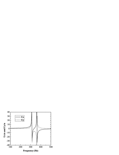
Fig. 2 shows the displacement of the core cylinders. It is observed that there are two resonances around Hz and Hz, denoted as mode and mode , at these frequencies the amplitude of the displacements of the cylinders in both directions are very large and experience a very sharp () change of phase. By solving for the vibration angle , it is found that the lower frequency resonance vibration is along the long semi-axis of the elliptical cylinders and the higher frequency resonance vibration is along the short semi-axis of the elliptical cylinders.
The appearance of two different resonance frequencies is not only a result of the variation of the coating thickness, it also relates to the contact area between medium 2 and 3 in vibration direction. Along the short semi-axis the effective thickness is larger than the one along the long semi-axis, however, the contact area is much bigger for short semi-axis vibration. These give rise to a higher resonance frequency in mode 4 than mode 2. A detailed description about the two modes without coupling effects can be found in [hirsekorn2006jap, ]. Between the two resonance frequencies, resulted from the splitting of the degenerate modes in symmetric resonator case, the phases of the vibration in and direction are reversed. This phase reversion brings about an interesting mode, denoted as mode , which demonstrates some notable physical properties.
To find out the implication of the phase reversion, we calculated the frequency dependance of force on epoxy matrix by the coated cylinder,
| (18) | |||
| (19) |
plotted in Fig. 3.
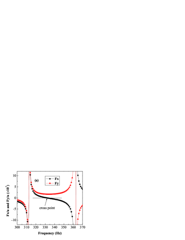
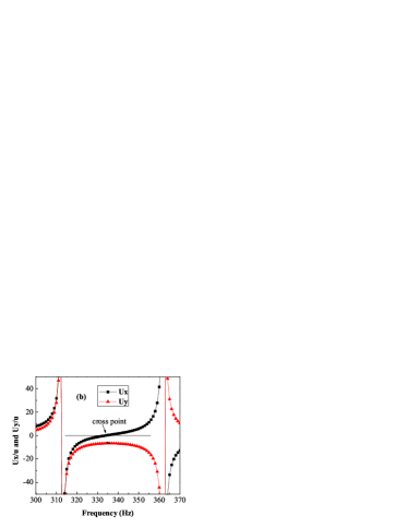
It can be seen from Fig. 3(a) that between the two resonance frequencies the force in direction is gradually changed from positive to negative, while the force in direction is always positive. The cross point frequency, denoted by , where the force in direction is zero, is close and a little higher than Hz. On this frequency, the amplitude of the displacement field in direction is a minimum, as is shown in Fig. 3(b). Here the effective mass density (EMD) for the coated resonator is a tensor and its -component is defined by , where is the volume of the coated cylinder. At this frequency, the EMD for the block defined liu2005prb as , who normalized by , is 0.06. The zerolike EMD for the block can give rise to an irregular wave propagation behavior in the direction, which will be discussed in detail below. This irregularity can not be simulated by single resonator in one unit cell. The nearest neighbor coupling effect of resonators plays an important role in this resonance mode.
Both -wave and -wave can exist in solids. Generally, the energy will be trapped by excited resonators, then gradually passed to the surrounding material in the process if the matrix’s absorption coefficient is not zero. In mode and mode , resonance appear in direction, the EMD tends to be infinity, thus elastic wave can expected to be totally reflected by non-dissipative material. Conversely, in mode , the EMD tends to zero in direction, so significant elastic wave transmission is expected.
III Finite Element Method Simulation
To validates the results, the finite element commercial software, COMSOL Multiphysics is used to simulate the vector displacement field in a unit cell with a pair of long coated elliptic cylinders immersed in epoxy, whose cross section is shown in Fig. 1. Periodic boundary condition is used in the direction. The material component properties and their corresponding dimensions are consistent with calculations in Sec. II. Instead of rigid assumption for the matrix and inclusion, some typical material parameters are assigned to the matrix and inclusion cylinders: the Young’s modulus for each components are, , , , the Poisson’s ratios are, , , , and the densities are, , , .
III.1 Resonance Modes
Triangular paver elements were used to construct finite element mesh of a unit cell with elliptic inclusions with nodes and elements. The mesh size is usually set according to the shortest wave length expected during the event comsol2007boston . For example, if is the number of elements per wavelength required for accurate modeling, is the slowest wave speed, and the largest frequency experienced in a frequency sweep, then the mesh size is determined by , (e.g. for quadratic element shape functions and for linear element shape functions). When rubber like materials are employed, the shear wave speed is typically the smallest and governs the mesh size needed in the solid. In the frequency range considered in this study, the wave-length in the matrix material is much longer than the side length of the unit cell.
The upper and down side were set as periodic boundaries to represent the infinite extent in direction, therefore the displacement of epoxy matrix in this direction is zero. The left and right edges were set as free sides receiving and transmitting traveling waves.
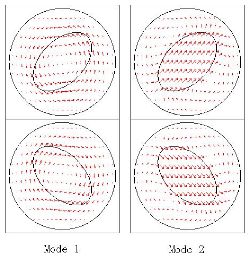
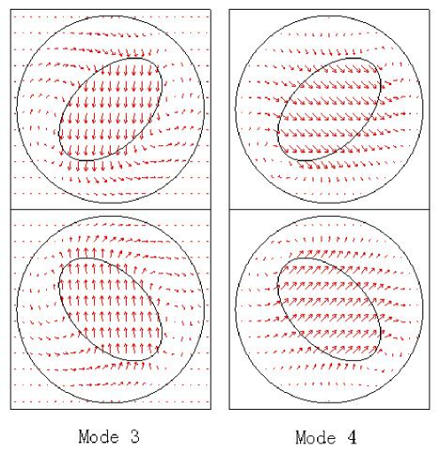
Fig. 4 shows the resulting simulated modes. For application reasons, higher rotational modes of the coating with an increasing number of integer nodes are not discussed here. Each one of the four modes related to the motion of the resonator, so all of the resonance frequencies of these modes are expected to be in the interesting low frequency regime. In mode , the core is rotating in the inclusion, inducing no net forces acting on the matrix, thus make no contribution to the wave insulation. Mode and mode are formed by the substitution of the circular shaped resonators by elliptic ones. Thus the degenerate resonance frequency in circular case is split into two modes. The resonance frequency in mode is , lower than the circular one (), which is for the parameters used here, according to Liu liu2005prb . The resonance frequency of mode is , which is higher than the circular counterpart.
Mode is the result of the interaction between two blocks in the unit cell, the resonance frequency is . The resonators are placed at geometry centers of the two blocks, while the orientation angles of the two resonators in one unit cell possess mirror symmetry with respect to the middle plane (see Fig. 1). The conjugate orientation angles for upper block and lower blocks in unit are and , respectively. The coupled two blocks give rise to a vibration mode, in which two resonators move in opposite directions along layer extension. The orientation angle can be set in the range for the upper block in Fig. 1, and simultaneously set in the range for the lower one. For the case or , this mode is identical to that of the single block in one unit cell, merged to the mode or mode . The resonance modes predicted by analytical methods seems to agree quite well with the finite element simulation results.
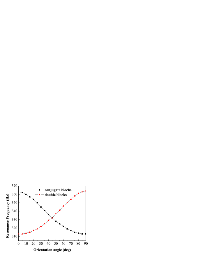
For different conjugate orientation angles, we obtained continuously changing resonance frequency under this coupling resonance mode (mode 3), with the other three resonance modes remains the same. Line with solid square in Fig. 5 shows that the resonance frequency dependant on the orientation angle of the elliptic cylinder. It decreases from , and reaches the minimum at . At both end of the curve, mode 3 disappeared, degenerating into that of the single block unit cell case. It also reveals that near , the slope achieves the maximum value. Line with solid trigon in Fig. 5 shows the doubled block in unit cell case. With the same orientation angle for both upper and lower blocks, the resonance frequency still dependent on the orientation angle, however, the vibration mode is no longer the same. This also lead to a different transmission property in the following section.
III.2 Attenuation performances
In order to provide efficient and reliable simulations for comparison with experimental data and other applications, the transmission properties is neededliu2000science ; hirsekorn2006jap and calculated as follows.
A periodic arrangement of unit cells with two coupling blocks illustrated in Fig. 1 is submerged in air. An incident plane wave is traveling along the positive direction. Upper and lower boundaries were still exerted periodical boundary conditions. On left and right side, the air domains were added, governed by the equation
| (20) |
which is provided by Time-harmonic analysis Module in COMSOL. The incident plane wave will encounter the air-epoxy boundary, inducing the displacement field in solids. The displacement field in solid domain is solved by employing Frequency response analysis Module. In order to illustrate the similarity of the equation form in the solid and air, we write the governing equations in the following form,
| (21) |
where , and are the wave speed in air, -wave speed and -wave speed in solid, respectively, and the repeated indices are summed over to . These two modules are then coupled through domain boundaries by domain variables and . The harmonic acoustic pressure in the air on the interface acts as a boundary load to the solids. The model calculates harmonic displacements and stresses in the solids, and then it uses the normal acceleration of the solid surface for air domain boundary to ensure continuity in acceleration.
Fig. 6 shows the elastic wave transmission spectrum from to . Single frequency harmonic waves were employed in the simulation, and the minimum step is . In the calculation, the absorption coefficient of the materials was taken to be zero, and transmission coefficient calculated for intensity of waves. The two dips and one peak observed in this figure are associated with the motion of inner resonator. The results from modal analysis are in good agreement with this transmission spectrum, in terms of the frequency positions of the two dips and the peak. The two dips, appearing at and , are corresponding to resonance vibration in Mode and Mode . Mode can not be observed in this figure, because the resonator remains symmetric in some extent. In the special case of elliptical resonators, whose center of mass away from its geometric center or the main axes are off the direction of wave propagation, rotational resonance can be expected to activate, bringing with an attenuation dip. For Mode , with conjugate orientation angles and , a peak at is observed. This peak appears as an manifestation of the zero effective mass density for the block in direction. The peak value is in fact , the lower value in the figure is an artifact due to the larger bin size in frequency used in the calculation. Accurate results around the resonance frequency will be given below.

No phase shift can be observed in the transmission spectrum. The two dips in transmission spectrum have been discussed by C. Goffaux goffaux2002prl and M. Hirsekorn hirsekorn2006jap . The resonance transmission peak and its corresponding mode is new.
At the resonance frequency the peak value is close to . Away from the resonance frequency the transmittance peak can be fitted neatly by the Lorentz form
| (22) |
where is the resonance frequency, is the full width at half maximum of the resonance, and the normalization constant. In Fig. 7 we plot the transmittance around the resonance frequency and the fit to a Lorentz curve, in this plot the frequency step is taken to be .
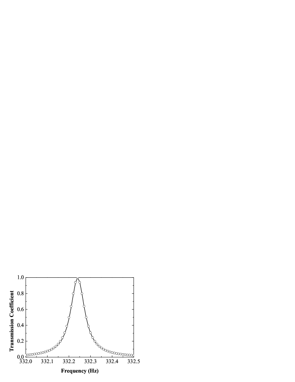
This result shows that the slab is effectively absent to the incident wave at a frequency near Hz, as predicted at the end of Sec. II. We denote this frequency by . It is worth noting that the is a little higher than , which in turn is slightly higher than the resonance frequency Hz. And all of the three are located in open interval . When gradually tend to from the resonance frequency, turns to zero, in other words, the effective thickness of the PC layer becomes smaller until zero, so that the attenuation effect is weakened.
In comparison, we also calculated the transmittance of a system with a unit cell where the two elliptic cylinders in the same orientation (), which is a case of double blocks in unit cell of a simple PC. The result is shown in Fig. 6 as dashed line. It can be seen that the resonance modes and disappear completely, and mode at frequency Hz (the cross point in Fig. 5) turns to be a transmission dip. Resonance mode analysis indicates that the whole rigid matrix takes part in to partially balance the momentum in direction induced by the cylinders, while cylinder resonance mainly exits in direction. This lead to large EMD in direction, and hence significant reflection for non-dissipative material. Actually, the minimum repeating unit of the system is the single cell. As investigated by Hirsekorn hirsekorn2006jap , it makes no difference when the unit cell is doubled.
IV Conclusion
In summary, the influence of the local asymmetry on the properties of the PCs at the low frequency in 2D has been studied. The analytical method used here are able to identify rotational mode, and the new mode whose vibration is perpendicular to the incident direction. We compared the results with the ones from finite element method, showing good agreement with each other. Transmission characteristic of a single layer PC are also calculated. The two dips are elastic wave attenuation corresponding to the common resonance modes, while the peak corresponds to the new resonance mode. Moreover, the peak can be tuned by simultaneously rotating the orientation angle of elliptical resonators of coupling blocks in a unit cell. This property provides a simple way to tune the resonance transmittance in locally resonant composite materials, leading to further opportunities for practical applications of the PCs.
References
- (1) Z. Liu, X. Zhang, Y. Mao, Y. Y. Zhu, Z. Yang, C. T. Chan, and P. Sheng, Science 289, 1734 (2000).
- (2) M. Hirsekorn, Appl. Phys. Lett. 84, 3364 (2004).
- (3) M. Hirsekorn, P. P. Delsanto, A. C. Leung, P. Matic, J. Appl. Phys. 99, 124912 (2006).
- (4) L. Y. Wu and L. W. Chen, J. Phys. D: Appl. Phys. 40, 7579 (2007).
- (5) F. Cervera, L. Sanchis, ., Phys. Rev. Lett. 88, 023902 (2002).
- (6) C. Goffaux, F. Maseri, J. O. Vasseur, B. Djafari-Rouhani, and P. Lambin, Appl. Phys. Lett. 83, 281 (2003).
- (7) J. V. Sánchez-Pérez, C. Rubio, R. Mártinez-Sala, R. Sanchez Grandia, and V. Gomez, Appl. Phys. Lett. 81, 5240 (2002).
- (8) C. Goffaux and J. Sánchez-Dehesa, Phys. Rev. B 67, 144301 (2003).
- (9) G. Wang, J. Wen, Y. Liu, and X. Wen, Phys. Rev. B 69, 184302 (2004).
- (10) G. Wang, X. Wen, J. Wen, L. Shao, and Y. Liu, Phys. Rev. Lett. 93, 154302 (2004).
- (11) For a review of this method see M.S. Kuswaha, Recent Res. Devel. Appl. Phys. 2, 743 (1999).
- (12) M. Kafesaki, R. S. Penciu, and E. N. Economou, Phys. Rev. Lett. 84, 6050 (2000).
- (13) M. G. Imhof, J. Acoust. Soc. Am. 100, 2969 (1996).
- (14) Y. W. Gu, X. D. Luo, and H. R. Ma (to be published).
- (15) M. G. Imhof, Geophys. J. Int. 156, 287 (2004).
- (16) R. Egli, A. Geiger, A. Wiget and H. G. Kahle, Geophys. J. Int. 168, 1 (2007).
- (17) A. Khelif, P. A. Deymier, B. Djafari-Rouhani, J. O. Vasseur and L. Dobrzynski, J. Appl. Phys. 94, 1308, (2003).
- (18) C. Goffaux, J. Sánchez-Dehesa, A. L. Yeyati, P. Lambin, A. Khelif, J. O. Vasseur, and B. Djafari-Rouhani, Phys. Rev. Lett. 88, 225502 (2002).
- (19) Z. Liu, C. T. Chan, and P. Sheng, Phys. Rev. B 71, 014103 (2005).
- (20) K.F.Graff, Wave Motion in Elastic Solids (Dover, New York, 1991).
- (21) M. G. Imhof, J. Acoust. Soc. Am. 97, 754 (1995).
- (22) A. J. Kalinowski, Except from the Proceedings of the COMSOL Conference 2007, Boston.