Authors e-mails can be built using the following syntax: ”firstname.lastname@ast.obs-mip.fr”
Fresnel interferometric arrays for space-based imaging: testbed results
Abstract
This paper presents the results of a Fresnel Interferometric Array testbed. This new concept of imager involves diffraction focussing by a thin foil, in which many thousands of punched subapertures form a pattern related to a Fresnel zone plate. This kind of array is intended for use in space, as a way to realizing lightweight large apertures for high angular resolution and high dynamic range observations. The chromaticity due to diffraction focussing is corrected by a small diffractive achromatizer placed close to the focal plane of the array.
The laboratory test results presented here are obtained with an 8 centimeter side orthogonal array, yielding a 23 meter focal length at 600 nm wavelength. The primary array and the focal optics have been designed and assembled in our lab. This system forms an achromatic image. Test targets of various shapes, sizes, dynamic ranges and intensities have been imaged. We present the first images, the achieved dynamic range, and the angular resolution.
keywords:
Orthogonal Fresnel zone plates, interferometric device, achromatism, field-resolution ratio1 INTRODUCTION
Fresnel arrays are interferometric devices involving many hundreds or thousands of ”basic” subapertures: mere holes punched in a large and thin foil. For each of these individual subapertures, diffraction occurs. The subapertures positioning law is designed so that the resulting interference produces the desired wavefront shape: for instance a spherical wavefront. The circular Fresnel Zone Plate (also called Soret zone plate), constituted of alternatively opaque and transparent concentric rings, is an example of Fresnel array: the distance from one transmissive ring to the other is adjusted so that the optical path to a point named ”focus” differs of one from one ring to the other. As a result constructive interference occurs at this point, resulting in an equivalent of focalisation: concentration of light.
In our approach, the orthogonal geometry has been preferred to Soret’s concentric rings for two main reasons: its allowance of vacuum rather than a transparent material for transmissive zones, and the higher dynamic range allowed in most of the image field. This optical scheme strongly reduces manufacturing and positioning constraints compared to those of standard interferometric arrays and monolithic mirrors. It also yields high dynamic range as well as larger field-resolution ratios than classical imaging interferometers. We propose this concept for high angular resolution imaging in future space projects (Koechlin et al 2005 [1]) .
An orthogonal Fresnel array of side involving Fresnel zones results in a focal length at its first order of interference, which can be written [1]:
|
.
|
(1) |
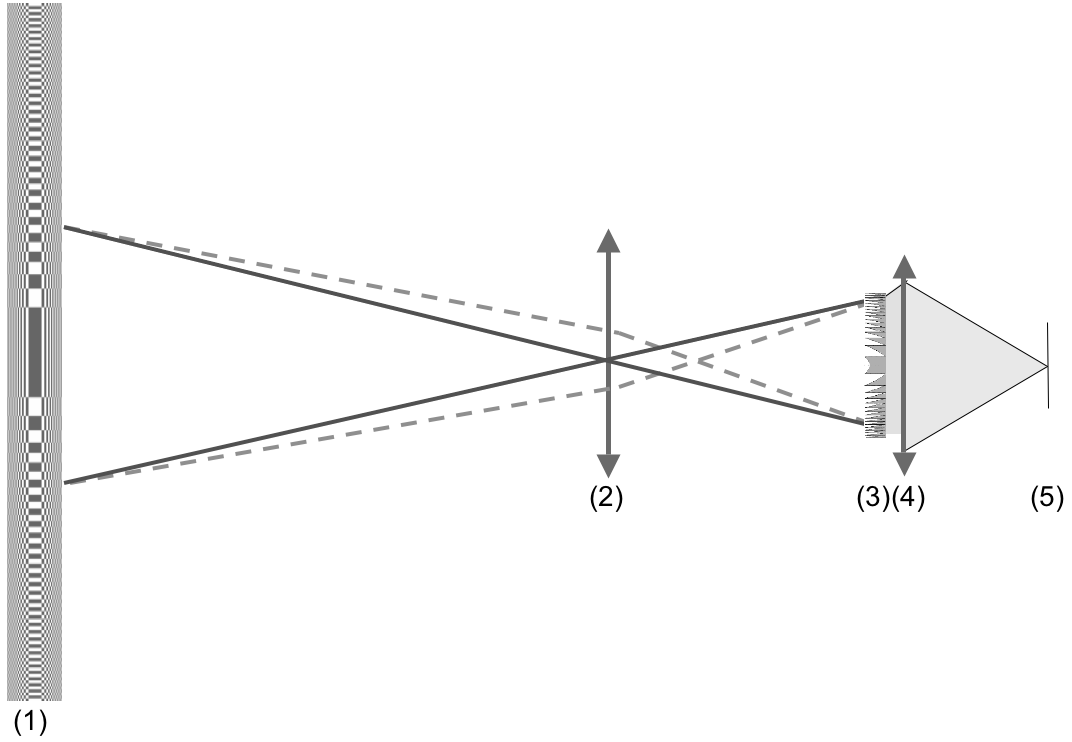
The unavoidable chromaticity of this kind of focussing element can be corrected using an optical scheme based on Schupmann studies [2] , and emerging from the chromatic correction of holograms developed by Faklis & Morris in 1989 [3] . The principle is to place in a pupil plane an optical device whose chromatic dispersion is opposite to that of the Fresnel array. That means in our case to use a diffractive optical device used at the order -1: a diverging Fresnel zone lens whose focal length varies in . Fig.1 presents the optical scheme.
 |
Following [Koechlin et al 2004 [4]] and [Serre et al 2005 [5]] , and thanks to a CNES111Centre National d’Etudes Spatiales R&T funding, we developed in the past two years at Université Paul Sabatier a Fresnel Interferometric Array breadboard testbed. The main focussing element is an 8 cm side square array and it is associated to optimized focal optics, leading to achromatic images and allowing diffraction limited performances. We present in this paper: firstly the constitutive elements of this prototype, and secondly the measured performances.
2 CONSTITUTIVE ELEMENTS
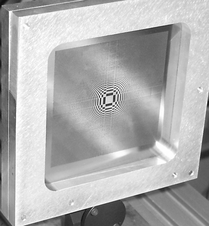
2.1 Fresnel interferometric array
Our Fresnel interferometric array is an 8 cm side orthogonal array, 58 Fresnel zones, i.e. 26680 subapertures, carved by UV laser in an 80 microns thick stainless steal foil. The resulting focal length is 23m at nm. In order to allow mechanical resistance of the array, the size of the individual apertures has been slightly decreased compared to the maximal possible dimensions. In our case, the smallest (outer) apertures are 140x140 microns squares instead of 170*170. This focussing array can be seen on fig.2.

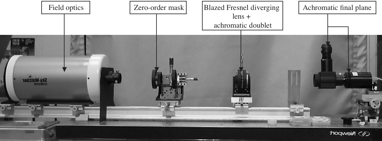
2.2 Focal optics
The focal optics are the direct application of the chromatic correction scheme presented in fig.1. The elements are (see fig.3):
- a field lens: in fact a Maksutov telescope associated to a 37mm diameter diaphragm, used off-axis to avoid central obturation;
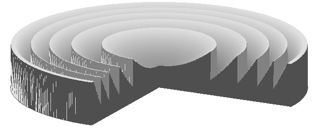
- pupil optics: a 116 zones diverging Fresnel lens, carved by ionic engraving using successive masks on a fused silica flat window. The useful diameter is 16 mm, which corresponds to the diagonal of the orthogonal Fresnel array imaged by the field optics. The five central zones of this lens can be seen for illustration on fig.4, and its efficiency dependance with wavelength can be seen on fig.5. The profile of this lens and the efficiency dependance have been obtained following the method exposed in [Serre 2007 [6]] (submitted). The individual grooves are 1.37 microns in depth, their different profiles are discretized with 128 depth levels, allowing transmission into order better than 90% through a spectral bandwidth.
- an achromatic doublet allows the formation of a real (i.e. non virtual) image on a B&W CCD camera. An eyepiece can also be placed for direct control.
A narrow cross mask allowing the elimination of order zero of the Fresnel array is placed at the focal plane of the Maksutov telescope.
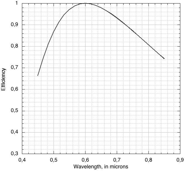
Here are presented the dependency of efficiency on wavelength, in two cases: lens manufactured with continuous slopes (nominal configuration, not our case), and lens manufactured with slopes approximated by a finite number of steps (our case, 128 steps). The two curves overlap, the resulting efficiencies being very close. The maximal efficiency is for nm, which is the wavelength the lens has been designed for, but remains better than 90% through a 200nm wide spectral bandwidth.
2.3 Source simulation
As the breadboard testbed is situated in a clean room, we need artificial sources. They are not really constitutive elements of the Fresnel interferometric imager, but are necessary to evaluate it. We disposed different types of sources in the focal plane of a parabolic mirror, collimating them along the optical axis of the Fresnel array. These different types can be source points, uniform discs or more shaped targets (see ”galaxy” image in next section). LEDs or halogene illumination, with or without spectral filters, has been used.
3 Measurements
3.1 Angular resolution and chromatic correction
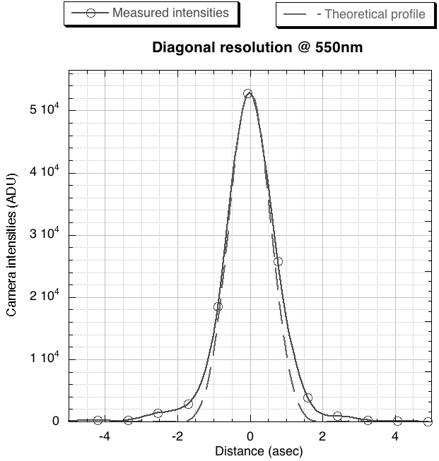
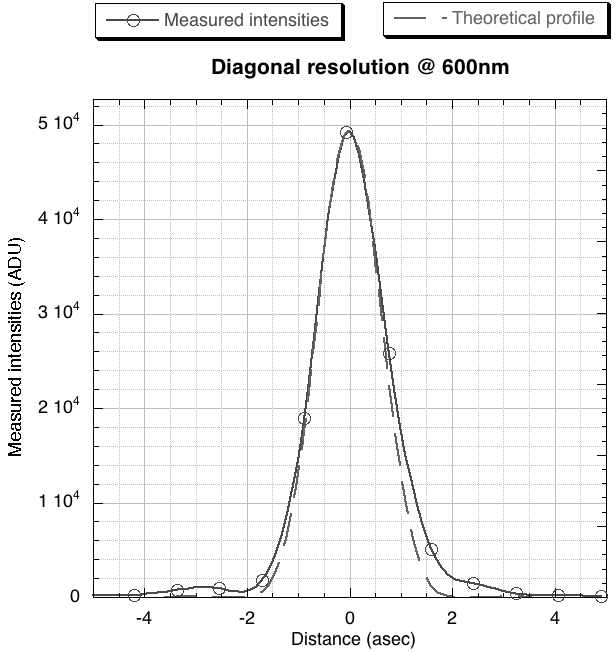
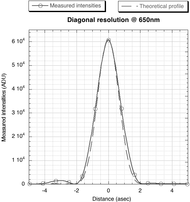
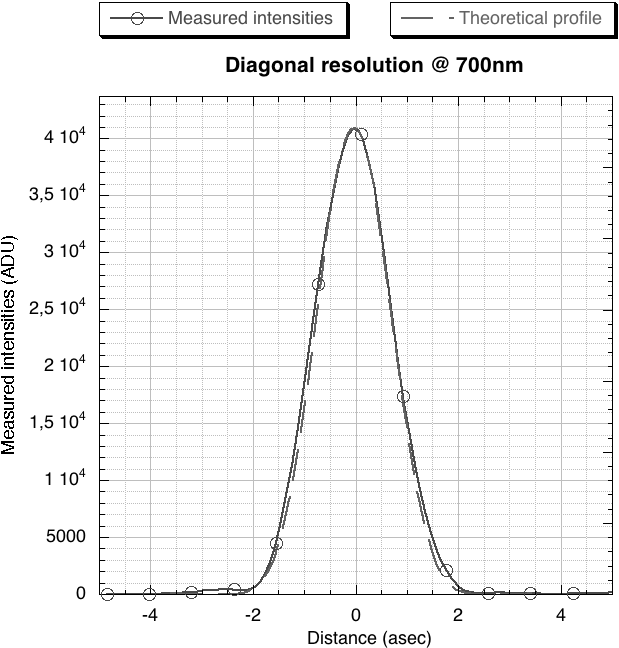
The theoretical angular resolution of the whole testbed is asec (at nm). In order to evaluate the effective resolution, we have used a pinhole (0.5 asec diameter) as a source, illuminated by halogen light and spectral filters centered on 550, 600, 650 and 700 nm (50nm bandpass for each filter). On fig.6 can be seen the comparisons between the theoretical, diffraction limited profiles and the measured profiles. The resolution is limited by the size of the Fresnel array and its associated diffraction limit for these wavelengths. The chromatic correction principle and its realization is consequently confirmed, as well as the design of the blazed diverging Fresnel zone lens.
3.2 Imaging capabilities
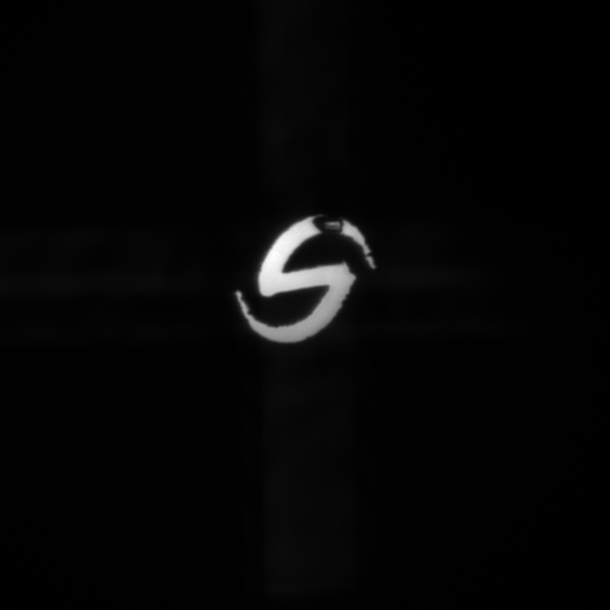
One can see on fig.7 an image obtained using the breadbord testbed: the source is a ”galaxy” target carved in a stainless steal foil. The ”galaxy” dimension from limb to limb is 450 microns, that is 72 arc seconds as seen from the Fresnel array. The illuminating source is a halogen lamp, whose spectrum spans throughout the visible domain, illustrating the excellent chromatic correction as exposed in previous section.
3.3 PSF modeling and rejection rate results
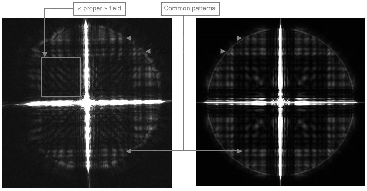
We have developed for the Fresnel interferometric array concept a plane-to-plane propagation software based on Fresnel diffraction algorithms, and have applied it to our breadboard testbed. The algorithms take into account the main orthogonal array, achromatic field optics, a ”zero-order mask” placed at the focal point of a parallel beam focussed by the field optics, the diverging Fresnel zone lens with all its groove profiles and the silica index variation, and finally the image reformation achromatic optics. An actual (acquired) PSF can be seen and compared to a simulated one on fig.8. To show the faint patterns of the PSF, the acquired image is highly overexposed.
In order to evaluate the rejection rate of the PSF, two images are presently necessary: a first one is acquired to measure the unsaturated level of the central peak, and then a second one is acquired with an exposure time multiplied 1000x times. Defining the rejection rate as the mean level of the ”clean” field of the PSF compared to the maximum level of the central peak, we can compare theoretical and measured values. They are of the same order of magnitude (see tab.1).
| Led’s maximal | Measured rejection rate | Theoretical rejection rate |
|---|---|---|
| intensity wavelength | ||
| 525 nm | 4.6e-6 | 1.2e-6 |
| 601 nm | 2.3e-6 | 1.2e-6 |
| 630 nm | 1.9e-6 | 1.5e-6 |
4 conclusion
We have presented in this paper the first results of an orthogonal Fresnel interferometric array breadboard testbed. We are able to confirm the efficiency of the achromatisation scheme retained, as well as the diffraction-limited performances and the ”wide” field imaging capabilities. The measured rejection rates are also in good agreement with computer generated previsions.
The next steps using this testbed are to evaluate rejection rates with two sources of different luminosity in the same field, to test different manufacturing processes for the blazed diverging Fresnel zone lens, and to assess Fresnel arrays subaperture shapes and layout, allowing higher transmission rates and dynamic ranges.
In the next few years, on one hand members of our team (and we hope new people !) aim to evaluate a 2 generation of ground-based testbed: its main evolutions will be an increase in dimensions (typically 20 cm side for the Fresnel array), higher number of Fresnel zones, and last but not least: real sky observation. On the other hand, studies will keep on being done to evaluate the performances of this kind of instrument and the potential astrophysical targets of a space-based Fresnel interferometric array concept. This space observatory could have a front array dimension of a few meters or more, and acquire data in the UV, visible or/and IR domains.
This work was supported by Université Paul Sabatier Toulouse III, CNRS, CNES, Thalès Alenia Space and the Fonds Social Européen.
References
- [1] L. Koechlin, D. Serre, and P. Duchon, “High resolution imaging with fresnel interferometric arrays: suitability for exoplanet detection,” Astronomy & Astrophysics 443, pp. 709–720, 2005.
- [2] L. Schupmann, “Die medial-fernrohre: eine neue konstruktion fr grosse astronomische instrumente,” Teubner B G , 1899.
- [3] D. Faklis and G. M. Morris, “Broadband imaging with holographic lenses,” Optical Engineering 28(6), pp. 592–598, 1989.
- [4] L. Koechlin, D. Serre, and P. Duchon, “Field-resolution ratio progresses for interferometric arrays,” in New Frontiers in Stellar Interferometry, Proceedings of SPIE Volume 5491. Edited by Wesley A. Traub. Bellingham, WA: The International Society for Optical Engineering, 2004., p.1607, W. A. Traub, ed., Presented at the Society of Photo-Optical Instrumentation Engineers (SPIE) Conference 5491, pp. 1607–+, Oct. 2004.
- [5] D. Serre and L. Koechlin, “Fresnel interferometric arrays: principle and exploitation,” in EAS Publications Series, EAS Publications Series 22, pp. 253–260, 2006.
- [6] D. Serre, “Design and numerical tests of a blazed diverging fresnel zone lens for an interferometric imager: optimal surface and optical efficiency,” Experimental Astronomy submitted, p. ??, 2007.