Third Level Trigger for the Fluorescence Telescopes of the Pierre Auger Observatory
Abstract
The trigger system for the Auger fluorescence telescopes is implemented in hard- and software for an efficient selection of fluorescence light tracks induced by high-energy extensive air showers. The algorithm of the third stage uses the multiplicity signal of the hardware for fast rejection of lightning events with above 99 % efficiency. In a second step direct muon hits in the camera and random triggers are rejected by analyzing the space-time correlation of the pixels. The trigger algorithm was tested with measured and simulated showers and implemented in the electronics of the fluorescence telescopes. A comparison to a prototype trigger without multiplicity shows the superiority of this approach, e.g. the false rejection rate is a factor 10 lower.
keywords:
Ultrahigh energy cosmic rays , Air fluorescence detectors , Software trigger1 Introduction
The Pierre Auger Southern Observatory in the Province of Mendoza, Argentina in the vicinity of Malargüe measures ultra-high energy cosmic rays by an array of 1600 Water-Cherenkov tanks (SD) and 24 fluorescence telescopes (FD). It combines the surface and the fluorescence detection techniques in a hybrid design for minimal systematic errors and optimum energy and angular resolution.
Already during construction the Auger collaboration measured the energy spectrum, the arrival direction, and the mass composition of cosmic rays above eV with high statistical significance. Recently published results [1] shed first light on the astrophysical important questions of possible sources, the energy spectrum and GZK-cutoff.
In the following sections the trigger system of the fluorescence telescopes is described in general with a particular focus on the software-implemented Third Level Trigger (TLT) as part of a multi-level trigger system. We specify the selection criteria (cuts) for efficient background rejection and measure the figure of merit of this new implementation.
1.1 FD system
The 24 FD telescopes are located in four FD stations around the perimeter of the 3000 km2 large SD array. They are designed to measure the fluorescence produced by secondary cosmic ray particles due to their interaction with molecules in the air. Each FD station comprises 6 telescopes with a Schmidt optical system that covers a azimuth times elevation field of view. Fluorescence light falls through a 2.2 m wide aperture with an UV transmitting filter and a corrector lens annulus on a spherical mirror and is focused on a photomultiplier camera [2]. The 440 camera pixels consist of hexagonal PMTs (type XP3062) arranged in a matrix of 22 rows and 20 columns.
The required high sensitivity of the PMT to single photons constrains the telescope operation to clear nights with dim moonlight. For safety reasons the stations are therefore equipped with a sophisticated slow control system which allows remote operation of all FD buildings from the central campus (CDAS) in Malargüe via a telecommunication network .
1.2 FD electronics
The PMT signals are fed to 20 front-end boards hosted in a 19” sub-rack. Each board processes the signals of 22 pixels of a single camera column. After analogue filtering and gain control at the First Level Trigger (FLT) board the signals are digitized with 12-bit resolution and 10 MHz sampling rate.
The digital data are continuously stored in a 16-bit memory per pixel, which is organized in 64 ring-buffers of 1000 words each. If the following trigger stage finds a fluorescence light track in the camera image, the data recording continues after a post-trigger delay of with the next available ring-buffer. Otherwise, the current ring-buffer data is overwritten after .
1.3 First Level Trigger (FLT)
While ADC values are stored in memory, the running sum of the last 10 samples is calculated to smooth the random fluctuations of the sky background. If the running sum exceeds an adjustable threshold the corresponding pixel is marked as triggered for a coincidence time.
The rate of triggered pixels is measured and kept constant around 100 Hz by regulating the individual thresholds. With this robust regulation scheme we prevent increasing random trigger rates despite slowly changing background light intensities during the night.
1.4 Second Level Trigger (SLT)
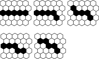
While the FLT trigger selects pixels seeing light levels above the common night sky background, we have implemented a further stage in hardware identifying tracks of triggered pixels in the camera image. For that purpose and for the readout of the data the sub-rack is equipped with one Second Level Trigger (SLT) board. It reads the triggered pixels from the FLT to construct an image of the camera in its memory. Within this image the SLT logic scans for small track segments of 5 adjacent pixels showing the patterns in fig. 1 by using highly parallel, pipelined pattern recognition logic [3]. In total, 37 163 different combinations of pixels are checked every microsecond. If at least 4 out of 5 pixels forming a pattern have triggered within a long coincidence time, the recorded data are kept as event.
1.5 Third Level Trigger (TLT)
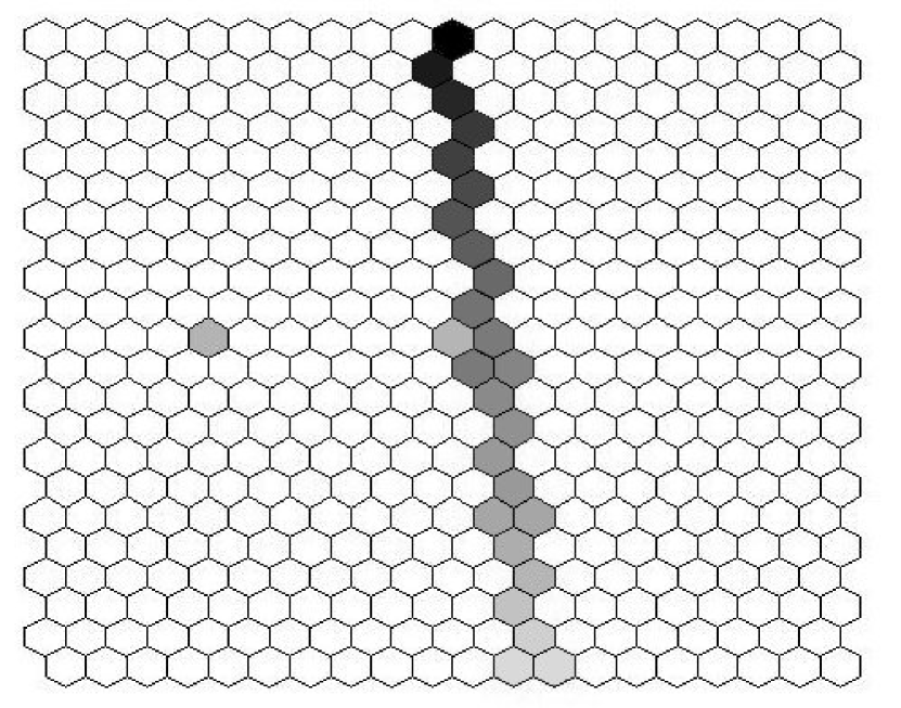
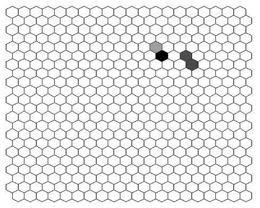
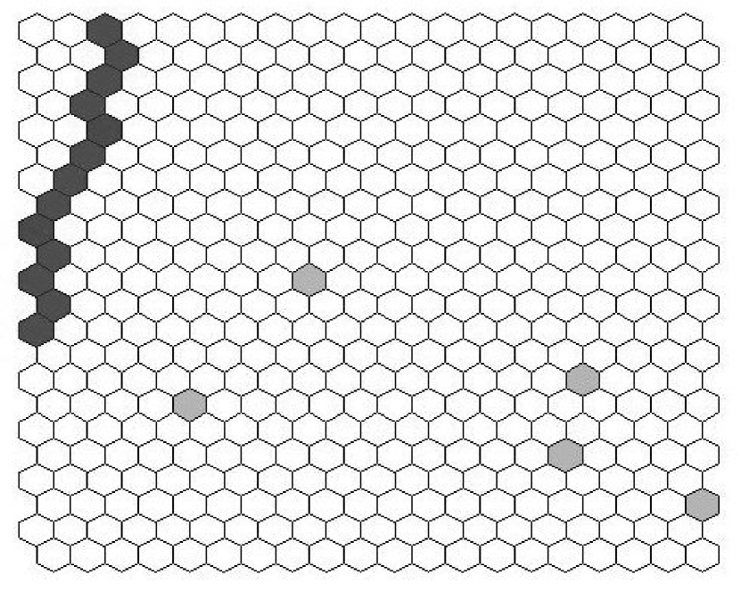
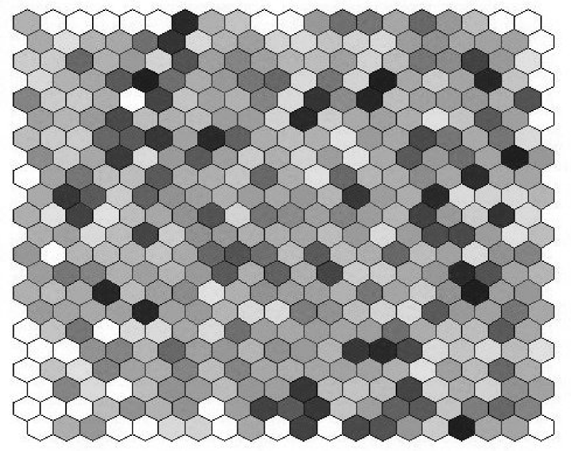
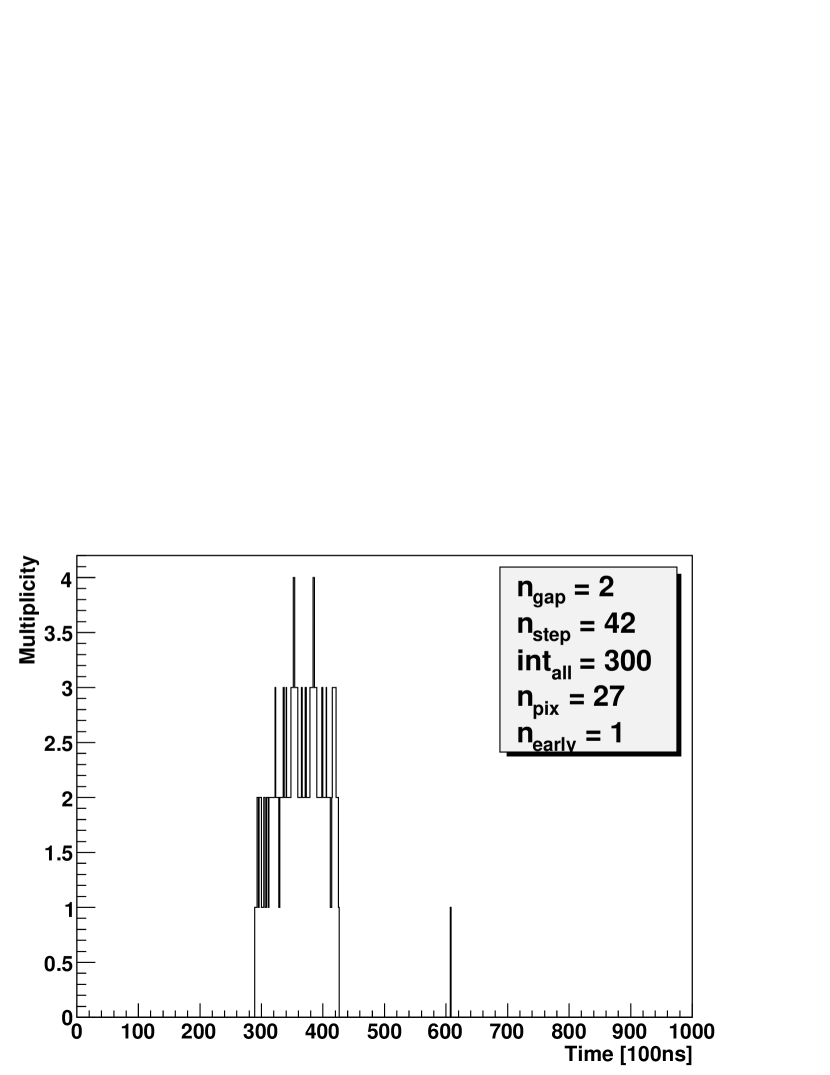
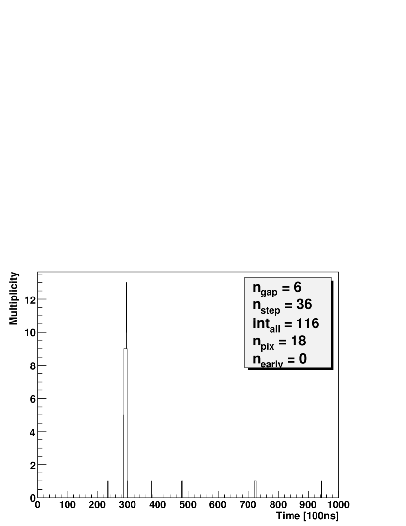
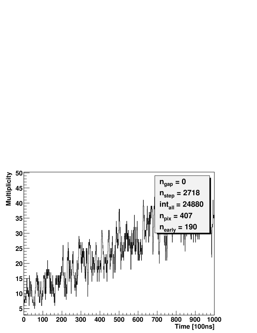
Different event types pass the first two hardware trigger levels. On the one hand there are extensive air showers we want to measure (s. fig. 2a), on the other hand different types of background events.
A small fraction of the background consists of random triggers of few noisy pixels without temporal sequence (s. fig. 2b). Another type of background are direct hits of muons in the PMTs, that result in tracks of synchronously triggered pixels (s. fig. 2c). But the main problem is distant lightning causing large areas of the camera to trigger in fast bursts (s. fig. 2d).

The software implemented third level trigger has to distinguish between background and extensive air showers, varying from dim and short tracks for distant showers up to an illumination of the whole camera for very close events. The key to the trigger decision lies in the timing information of the pixels: Real shower events always show a temporal development along their track.
The prototype TLT identifies background by analyzing the ADC data and checking for a temporal sequence inside the 5-pixel SLT-pattern. The major disadvantage of this approach was the very time consuming readout of ADC traces, needed to determine the pixel time. Especially during lightning, bursts of events with many pixels were rejected too slowly, all FLT buffers were filled and dead time was introduced.
In this paper we will describe a new two-stage TLT. In a first step lightning events are fast and efficiently rejected by cuts on the hardware multiplicity data. In the second step the time sequence of the pixels data is analyzed using their ADC data.
In the DAQ chain the TLT is followed by the Event Builder, which merges concurrent events in neighboring telescopes together. A subsequent algorithm tries to calculate the preliminary shower direction to form a hybrid trigger (T3) for the suface detector. Finally the event is stored on hard disk and transmitted later on to the central campus via microwave uplink.
1.6 Data sample
For the developement of the new trigger we need a set of background events and extensive air showers. Therefore we randomly selected 8839 events from one year of data taking and manually separated them into 2425 shower and 6414 background events. This classification was done very conservative to prevent the misinterpretation of potential showers as background. The separation was successfully cross-checked by a reconstruction with the detector simulation and analysis framework Offline[4]. None of our events classified as background, but 25 % of our shower candidates can be reconstructed. This confirms the conservative character of our manual classification.
After using this data sample for the trigger developement, we determine the background rejection efficiency with a second batch of background events independentely from the training data. The acceptance of shower events, especially at high primary energies, is checked with Monte-Carlo-simulated showers.
2 Multiplicity based trigger
In order to speed up the trigger decision, the new TLT has to abstain from reading out ADC traces until the data load is sufficiently reduced. As the digital electronics of FLT and SLT is based on flexible re-programmable FPGA logic it was easy to update the firmware to provide a hardware calculated multiplicity.
The multiplicity is the number of simultaneously (i.e. within 100 ns) triggered camera pixels. A pixel contributes to the calculation of the multiplicity as long as its running ADC-sum exeeds the FLT threshold. Contributing pixels of one column are counted at the FLT, the total sum for the full camera is evaluated at the SLT. The hardware implementation limits the multiplicity to a maximum value of 63.
The chronological sequence of the multiplicity values with full 100 ns time resolution describes the temporal development of the overall camera picture. This multiplicity signal is directly accessible from the hardware and therefore particular suitable for effective and fast background discrimination.
2.1 Multiplicity parameters
In order to capture the characteristics of the multiplicity signal, the following 5 parameters were selected, distinguishing well between background and shower events:
-
Number of gaps in the multiplicity signal, i.e. the number of periods without triggered pixels.
-
Sum of steps in the multiplicity signal; the absolute values of steps both up and down are added.
-
Integral of the multiplicity signal over the full event window of 1000 values. It is equal to the number of triggered pixels times their trigger duration.
-
Number of triggered pixels. This is not a multiplicity parameter, but an overall characterization of the event.
-
Number of pixels, which trigger in the first 5 s of an event. This value is no real multiplicity parameter either.
We developed 5 independent cuts on these parameters using the sample of manually classified events mentioned in sec. 1.6 as training data set.
2.1.1 Cut 1
The SLT divides the readout window in a s pre-trigger and a s post trigger window. Only few pixels should trigger in the first microseconds of each event. However during lightning the general variance of the ADC-traces is such high, that the random pixel trigger rate increases strongly. Hence we keep only events with less than 6 pixels triggering within the first s of the event:
| (1) |
This constraint already rejects 51.7 % of the background in our data sample without rejecting any showers.
2.1.2 Cut 2
Far away showers cause long pulses in the ADC traces, as it takes them longer to pass the field of view of a single pixel. E.g. a vertical shower at 10 km distance illuminates each pixel for about s. In contrast close showers have shorter, but much higher pulses. As the FLT uses a boxcar sum over 10 values for the trigger, a short and high peak leads also to a trigger lasting 10 clock cycles.
Therefore showers provide independently of their distance a minimum pixel trigger duration of about 1 s while background events frequently consist of many short pixel triggers.
The integral of the multiplicity signal is the sum of all pixels times their trigger duration. The cut
| (2) |
rejects all events where a lot of pixels trigger for less than s. 28.3 % of the background is rejected by this cut without losing any shower event
2.1.3 Cut 3
In shower events pixels trigger one after the other, while lightning causes rather independent pixel triggers. For this reason the multiplicity signal of showers usually consists of continuous areas, while the signal of background events is interrupted by gaps.
By accepting only events with
| (3) |
we reject 27.7 % of the background.
2.1.4 Cut 4
Sometimes strong lightning events have so many pixel triggers, that they form a continuous area in the multiplicity signal by chance. These events will not be rejected by cut (3). However, as the fluctuation of the multiplicity signal is higher than for shower events, a cut on can identify such events.
| (4) |
This constraint rejects all events, where more than 25 pixels trigger twice, which affects 33.1 % of the background events. Only one noisy shower candidate is rejected.
2.1.5 Cut 5
During very intense lightning the multiplicity signal gets saturated at its maximum value of 63. In the saturated region the multiplicity is constant and the evaluated value of is getting lower. Thus cut (4) does not work. Such events are identified by a cut on large values of :
| (5) |
9.5 % of the background is rejected, no additional shower event is lost.
2.1.6 Results of the multiplicity trigger
The 5 cuts widely overlap each other reducing their combined rejection efficiency. In total 58.2 % of the background in our data sample is rejected.
The cuts reject background independently from each other, so their order does not matter in terms of rejection efficiency. So the fastest and most efficient cuts are performed first in order to reduce data load for the next steps.
The fraction of background event rejected by the multiplicity cuts strongly depends on the number of triggered pixels : While 99 % of the large background events with are rejected, only 7 % of the smaller events are caught (s. fig. 3).
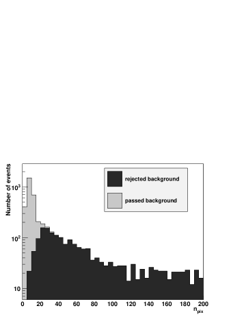
Although cut (2) - (5) contribute only by a few percentage points to the overall rejection efficiency, they play an important role to increase rejection of large background events up to 99 %.
Unfortunately it is not possible to enhance the efficiency at low pixel numbers with additional multiplicity cuts, the multiplicity information is not detailed enough. For example the signature of a muon hit (short and high ADC-Pulses at the same time) fades out in the multiplicity signal, as the trigger time is extended to 1 s by the boxcar sum of the FLT, and only the sum of all pixels is displayed.
However, the critically high data load from bursts of events with high pixel numbers during lightning is eliminated in a fast and efficient way.
3 Analysis of the space-time correlation
For the reduced data stream of events with few pixels it is now feasible to readout complete ADC traces in order to improve rejection of muon hits and random triggers without deadtime. For this purpose we developed an algorithm that analyses the temporal sequence of the triggered pixels with full 100 ns time resolution in 4 steps:
3.0.1 Finding the shower center
At first we have to remove disturbing pixels aside from the real shower track. Scanning the matrix of triggered pixels row by row, the algorithm finds groups of connected pixels (allowing maximal 1 gap). The group with the largest number of pixels is regarded as forming the ”shower center” which is used in the subsequent analysis.
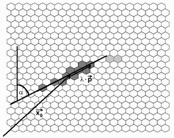
3.0.2 Direction of the shower center
A straight line parameterized in the form (6) is fitted to the pixels of the shower center using the least square method (s. fig. 4). For each pixel its line position is calculated and the pixels are sorted by rising -values.
| (6) |
3.0.3 Time assignment
The pixel times must be determined by analyzing the ADC data. The FLT-pixel time is not suitable, as the time of threshold crossing is blurred by the 10 entry running sum. Good results are achieved by a simple maximum search of a running 2-bin ADC-average. As we can easily access the second level trigger time with a low resolution of s, the time assignment can be accelerated by constraining the maximum scan to a s window around the SLT time.
The number of entries in the moving average is a compromise between best noise suppression and acceptable time-blurring. Another compromise is the width of the search window: a wider window around the SLT time might find a higher ADC pulse, but increases the danger of finding wrong pulses. Both values were varied and tested, above listed values are used.
Randomly triggered pixels are removed from the shower center group, if their pixel time differs by more than 2 rms deviation from the average shower center time.
3.0.4 Check for temporal sequence
Finally the algorithm runs through the list of -sorted pixels to count how often the time difference is positive (increment of ) or negative (increment of ). If the time of adjacent pixels is equal, that pixel is not taken into account. The defined temporal propagation of showers requires either always increasing or always decreasing pixel times. Thus the absolute value is a good criteria for shower events independent from their direction.
A single randomly triggered pixel has big influence on the temporal sequence of showers with few pixels. Therefore shower centers with less than 7 pixels are checked again to verify, if their value of increases when one pixel is left out of the , calculation.
Figure 5 displays the distribution of the parameter for shower and background events. The cut
| (7) |
rejects events with only a weak temporal sequence.
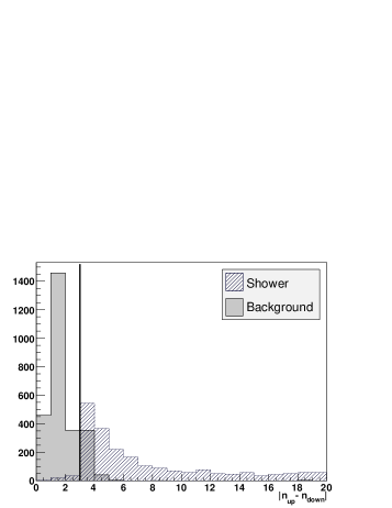
This last cut increases the background rejection up to 93.6 %, but it also rejects 2.4 % of our shower candidates. Those 56 falsely rejected shower events were checked in detail: The majority of them could not be reconstructed, their manual classification as shower is questionable. Only 6 of the rejected events could be sucessfully reconstructed, always yielding an energy below , which is close to lower energy limit of the detector.
Because the background rejection of our multiplicity trigger is already good enough at high pixel numbers, the space time correlation cut is only applied for events with less than 25 pixels in order to increase processing speed.
4 Trigger performance
After the cuts and algorithm of the new trigger had been optimized, we performed several tests in order to benchmark our trigger and compare its performance with the prototype setup.
4.1 Background rejection
To verify the high background rejection efficiency, we used 24306 events from randomly selected background files as an independent data set. These background files are recorded during normal data taking for monitoring purposes. 1 % of the events rejected by the prototype TLT, and 10 % of the events rejected by the last trigger stage (T3) are stored. To get a realistic composition of background events each prototype TLT rejected event has to be weighted statistically with the factor 10.
Taking into account this weight factor we determine a background rejection of 95 % for the new TLT implementation (to be compared to 74 % for the prototype TLT).
As expected, the efficiency rises with the number of pixels, 99 % of the background events with more than 25 pixels (e.g. lightning) are rejected.
4.2 Acceptance of simulated showers
The extreme rareness of ultra high energetic cosmic rays, limits their statistics in measured data. In order to check the trigger acceptance to showers in the full primary energy range we used simulated events. The simulation was done with Offline [4] using CONEX-showers [5] with energies between and . Proton- and iron-induced showers were generated in equal parts, their positions were randomly distributed over the measuring field. The simulation took into account the fluorescence yield, light propagation and absorption, the properties of the telescope hardware, readout, FLT and SLT.
The fraction of falsely rejected showers (called FRS in the following) for the new TLT and the prototype are compared in table 1. As some simulated showers are close to immanent detection limits due to large simulated distance and low primary energy, we also checked the events for reconstructability. Events with sufficient data quality for reconstruction are accepted much better by our TLT.
| All events | Reconstructable events | |
|---|---|---|
| Number of events | 9257 | 5630 |
| FRS, prototype TLT | 9.8 % | 6.1 % |
| FRS, new TLT | 0.68 % | 0.18 % |
4.2.1 Energy dependence
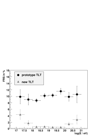
Since the measurement of the energy spectrum is one of the main goals of the Pierre Auger Observatory, determination of the energy dependent trigger acceptance is essential.
Figure 6 shows that the fraction of rejected showers rises with energies below and above . The higher FRS at low energies is simply explained by difficulties measuring dim showers close to the detector’s energy threshold.
Showers of very high energies are rejected for other reasons: The traces of near showers are often so extended that they split up in two telescopes (multi-mirror event). The telescope viewing the small outermost part of the shower trace might reject this mirror-event with few pixels. In the highest energy-bin with 140 events, 2 of 3 rejected showers are such multi-mirror event tails. Of course the showers are not lost completely, as the neighboring telescope records the main part of the shower trace. To record the complete shower trace anyhow, an additional inter-camera-trigger is under development.
Allowing for this energy dependence and a particle flux the false shower rejection ratio in reality is dominated by the low energies to a value of 3.8 %. This result is improved to 0.6 % when only taking into account showers with .
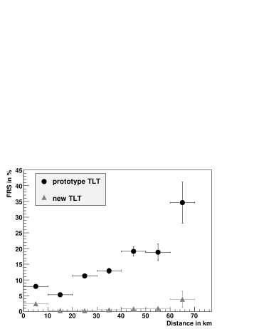
4.2.2 Distance dependency
As shower brightness and pulse width both depend on shower distance, this is one of the most important variables to parameterize for the detection probability.
The rise of the FRS with shower distance is small up to 60 km for the new TLT, especially when compared with the prototype TLT (s. fig. 7). Very near showers are also rejected more frequently, as they develop very fast and it becomes difficult to verify a temporal sequence within the limits given by the time resolution of the apparatus.
Other shower parameters like the kind of primary particle or the shower’s direction were also examined and no trigger dependency was found.
4.3 On site commissioning
The real-time performance of the new trigger was tested during 5 nights of the August shift 2007 in one FD building. For direct comparison we operated telescope 1, 3 and 5 with the new and telescope 2, 4 and 6 with the prototype TLT. Thus weather and background light conditions were comparable for both telescope sets.
The prototype and the new TLT achieved background rejection efficiencies of 66 % and 94 % respectively. These values are in good agreement with the offline estimations in section 4.1.
Another goal of the new algorithm was to speed up the TLT decision. Table 2 summarizes the processing speed as measured during commissioning. Especially background events with lots of pixels as they occur in bursts during lightning are rejected several orders of magnitude faster.
| Decision time | prototype TLT | new TLT |
|---|---|---|
| events, | 25 ms | 3.7 ms |
| events, | 109 ms | 0.05 ms |
| all events | 26 ms | 3.5 ms |
5 Conclusions
We have developed a new TLT software on the basis of the existing fluorescence telescope hardware. The main goals of the development were an improved background rejection and fast trigger decision in order to handle bursts of background events during bad weather conditions.
These aims are achieved by using a two stage algorithm: In a first step we use the temporal developement of the number of triggered pixels in an event. This multiplicity signal is calculated in hardware. Five independent cuts on multiplicity parameters are used to reject background events.
Although the multiplicity trigger works fine for the main data load of events with many illuminated pixels, it fails in distinguishing short shower traces from background events with less than 25 pixels. For these events we need a more detailed analysis of the temporal appearance of the triggered pixels along the shower track.
The acceptance of extensive air showers was determined to be better than 99 % using simulated events in the energy range from to . At the same time 95 % of the background is rejected, during bad weather conditions the rejection efficiency of events with more than 25 pixels rises above 99 %. As the algorithm abstains from single pixel analysis for these events, the decision is done fast enough to reject background in almost real-time.
The new TLT was installed into the trigger chain in September 2007. This enhancement improves the data quality of the fluorescence detector and noticeably simplifies data taking especially during the rainy season.
References
- [1] The Pierre Auger Collaboration, Correlation of the Highest-Energy Cosmic Rays with Nearby Extragalactic Objects, Science 318 (5852):938–942, 2007.
- [2] The Pierre Auger Collaboration, Properties and performance of the prototype instrument for the Pierre Auger Observatory, Nucl. Instrum. Meth. A523:50–95, 2004.
- [3] M. Kleifges for the Auger Collaboration, The fluorescence detector electronics of the Pierre Auger Observatory, Nucl. Instrum. Meth. A518:180–182, 2004.
- [4] S. Argirò et al., The Offline Software Framework of the Pierre Auger Observatory. Nucl. Instrum. Meth., A580:1485–1496, 2007.
- [5] T. Bergmann et al., One-dimensional hybrid approach to extensive air shower simulation, Astropart. Phys., 26:420–432, 2007.