Dynamics of coupled spins in quantum dots with strong spin-orbit interaction
Abstract
We investigated the time dependence of two-electron spin states in a double quantum dot fabricated in an InAs nanowire. In this system, spin-orbit interaction has substantial influence on the spin states of confined electrons. Pumping single electrons through a Pauli spin-blockade configuration allowed to probe the dynamics of the two coupled spins via their influence on the pumped current. We observed spin-relaxation with a magnetic field dependence different from GaAs dots, which can be explained by spin-orbit interaction. Oscillations were detected for times shorter than the relaxation time, which we attribute to coherent evolution of the spin states.
pacs:
73.63.Kv, 72.25.-bDouble quantum dots (DQDs) are considered as model systems for quantum bits (qubits) in spin-based solid state quantum computation schemes Loss and DiVincenzo (1998). The combination of single qubit rotations and so-called two-qubit gates would facilitate universal quantum operations. Fast control of the exchange coupling allows to coherently manipulate coupled spin qubits Petta et al. (2005) and to quantify the relevant spin relaxation and coherence times Johnson et al. (2005); Laird et al. (2006) in GaAs based quantum dots. Beyond the two-qubit operations, controlled rotation of a single spin has been demonstrated Koppens et al. (2006). Especially appealing for a scalable technology is the possibility to perform these single qubit operations with electric gate signals mediated by the spin-orbit interaction (SOI) Nowack et al. (2007). This has stimulated the interest in alternative systems with strong spin-orbit interaction, as recently detected in InAs nanowires Fasth et al. (2007); Pfund et al. (2007a) and carbon nanotubes Kuemmeth et al. (2008).
Complementary to being a tool for single spin rotation, SOI can have substantial influence on two-qubit operations via exchange gates Burkard and Loss (2002); Stepanenko et al. (2003) or direct spin-spin coupling Trif et al. (2007). Here we investigate the dynamics of two coupled, spatially separated spins in a DQD fabricated in an InAs nanowire, where SOI is orders of magnitudes stronger than in GaAs Fasth et al. (2007); Pfund et al. (2007a).
We employ a charge pumping scheme Pothier et al. (1992); Fuhrer et al. (2007) to measure the time dependence of two-electron spin states by transport through the DQD. When the system contains two (excess) electrons, the Pauli exclusion principle suppresses certain transitions Ono et al. (2002). This spin-blockade (SB) can be used to electrically determine the spin state Koppens et al. (2006); Johnson et al. (2005); Petta et al. (2005); Pfund et al. (2007b). The pumped current is strongly reduced in the blockaded direction compared to cycling in the opposite way, which reflects the spin transition rules leading to the SB. We concentrate on the evolution of those two-electron spin states, where the electrons are distributed between the coupled dots (the occupancy). A decay of the SB is observed on a timescale of ns, which we relate to relaxation towards a state with -triplet character. In contrast, no decay is observed up to several s when both electrons occupy the same dot (the occupancy). The observed time-dependence differs significantly from measurements in GaAs DQDs and cannot be explained by models accounting only for hyperfine interaction. Instead, the magnetic field dependence is consistent with SOI mediated relaxation Amasha et al. (2008); Meunier et al. (2007); Hanson et al. (2005). On a shorter timescale (ns), we detect oscillations between the spin-states. These findings suggest, that coherence times are similar to GaAs DQDs.
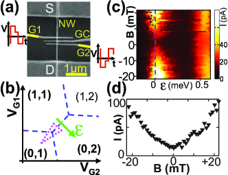
We investigate a DQD formed by lithographically defined top-gates on an epitaxially grown InAs nanowire Pfund et al. (2007a, b), see Fig. 1(a). Transport measurements were performed in a dilution refrigerator at an electronic temperature of mK. A magnetic field can be applied parallel to the nanowire. Thermalized coaxial cables allow to apply voltage pulses with a typical rise time of ns to the top-gates. Bias tees at low temperature are used to admix AC and DC signals.
The gates define tunnel barriers and tune energy levels in dot 1 and 2. The center gate separates the two quantum dots. In the presented measurements, the center gate voltage is fixed and defines a tunnel coupling eV. Due to Coulomb blockade, the number of electrons in each dot is fixed for specific regions in the --plane van der Wiel et al. (2002). A part of the charge stability diagram is sketched in Fig. 1(b) and the electronic configuration is labeled by the number of electrons n in dot 1 (m in dot 2). These labels refer to the number of excess electrons in addition to spin-less filled shells of electrons Pfund et al. (2007a, b). Variation of the gate voltages along the green arrow in Fig. 1(b) detunes the levels in the dots by an energy .
In the case without spin dependent interactions, two electrons form either a singlet or triplet states ( denotes the z-component of the spin state). If the detuning is positive, both electrons are in the same dot and the ground state is the singlet . Triplets in have higher energies because they involve occupation of an excited orbital state. For , the singlet and the triplets are close in energy at zero magnetic field Koppens et al. (2005). Since tunneling preserves spin, a transition from a -triplet to is forbidden. Various experiments show that the singlet-triplet picture describes well the SB in GaAs DQDs Ono et al. (2002); Johnson et al. (2005); Petta et al. (2005); Koppens et al. (2005). In the following, this model is used for a qualitative description.
In Fig. 1(c) the current through the device is shown as a function of detuning and magnetic field , when no pulses are applied to the gates. A finite source-drain bias mV is applied. Sequential transport from to is in principle allowed, if the relevant levels are within the bias window: . Around zero field however, the current in Fig. 1(c) is strongly suppressed. In the basic picture described above, blockade arises once a -triplet is loaded: the state can neither tunnel to nor unload again to the source, if it is within the bias window. Not explained by this model is the strong current which sets in for small magnetic fields as shown in Fig. 1(d). This behavior is not reported in GaAs DQD tuned to the same coupling, but also occurs in other DQDs with strong SOI, as recently found in carbon nanotubes Kuemmeth et al. (2008); Churchill et al. (2008). In the following, we identify SOI mediated relaxation to as the origin of this difference to GaAs.
To probe the time evolution of the spin-states, we use pumping cycles where single electrons are shuttled through the DQD Pothier et al. (1992); Fuhrer et al. (2007). Fast (ns) pulses are applied to the gates in a loop around the ---triple point in the charge stability diagram. The voltages are switched rapidly along the dotted line in Fig. 1(b) and waiting times , , are spent in each state. The pumped current is measured with zero bias across the device and each point is averaged over s.
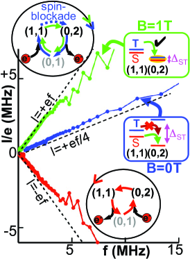
In Fig. 2 the pumped current is shown as a function of cycling frequency for cycles with ==. The behavior is different for the two possible pumping directions. The lowest (red) curve shows the result for anti-clockwise cycling (lower round inset). The current is negative and equal to the elementary charge times the cycle frequency up to several MHz as expected. When cycling in the opposite direction (upper round inset), the current is reversed and the pumping efficiency is sensitive to magnetic field. For T (middle curve, blue), we find a significantly reduced current compared to the anti-clockwise direction. If a high magnetic field T is applied, charge is again pumped with the full efficiency of one electron per cycle (upper curve, green).
We never observed pumping currents higher than one electron per cycle. The tunnel rates in our device correspond to timescales ns (estimated from measurements as in Fig. 1(c) Pfund et al. (2007a)). The pulses are slow with respect to the tunnel rate. Therefore the charge configuration during the cycle follows the ground state in the charge stability diagram - provided the transition is not forbidden by spin selection rules. Beyond that, the pumping efficiency depends on the size of the pulse loop in Fig. 1(b). For example, if the -corner is chosen at a too high detuning, the transition from to occurs by electron escape via Johnson et al. (2005). We adjusted the pulsing parameters so that these processes are minimal.
The pumping scheme allows to study the time evolution of the quantum states involved in the SB. For a tolerable signal-to-noise ratio of the pumped current, the total cycle times should be shorter than s. Within this limit, we observe no dependence of the pumping efficiency when varying separately the times and (not shown). However, has a strong influence on the pumped current.
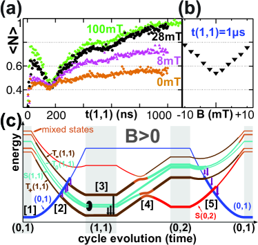
In Fig. 3(a), the average number of pumped electrons per cycle is plotted as a function of . To maintain a well detectable signal, the total cycle period is fixed to s. Since only depends on for these timescales, we fix ns and compensate the time spent in by shortening the time in correspondingly. A monotonic long-time increase of is found for times ns 111The minimum at ns is also observed for different total cycle periods and in schemes, where only is varied. The origin is not fully understood, but it does not affect the analysis of the relaxation process above ns.. At finite field, this effect is much more pronounced than at T.
The long-time limit of is studied as a function of -field in Fig. 3(b). For s, is sensitive to magnetic fields of a few mT. This behavior is in line with the field dependence of the current through SB at finite bias (Fig. 1(d)).
In order to analyze the behavior of the pumped current, we use the singlet-triplet model for SB 222Since the singlet-triplet splitting is much larger then the energy scale of the SOI Pfund et al. (2007a), the -states are reasonably described as triplets and singlet . The nature of the -levels could however be strongly modified by SOI.. The values of the pumped currents in Fig. 2 are related to the spin-transition rules between the corners of the pumping loop. For the anti-clockwise cycle (lower round inset), the transition from to is always allowed and one electron is transfered from right to left during each roundtrip. In the opposite direction (upper round inset), the transition from to is spin selective. The triplets are blocked and only the singlet can pass, which reduces the pumped current. At T, the excited triplet comes close in energy to the ground state and both are mixed by SOI Pfund et al. (2007a). This way SB is lifted and the full pumping current is recovered.
To understand the decay in Fig. 3(a), we analyze the spin-selective transition - for different magnetic fields. A contribution to the pumped current is generated only by those -states, which are transfered into a singlet during the pulse. In other states, the electron is blocked.
At T, all -states are close in energy Koppens et al. (2005); Petta et al. (2005) and become mixed by different spin coupling mechanisms during the time . The pumped current then reflects the overlap with the singlet. In Fig. 3(a), the curve for T shows only a weak time dependence. This supports that there is no preferential evolution towards a certain state, but mixing between all states.
For finite field, the level evolution along the triangular pumping cycle is sketched in Fig. 3(c). Between the and corners, triplets and singlet levels would cross at two points (label [4] in Fig. 3(c)). In the presence of SOI or hyperfine interaction, hybridization of states leads to avoided crossings at these points Koppens et al. (2005); Reilly et al. (2008).
Zeeman splitting lowers the energy of the state with -character. Relaxation to this new ground state occurs during the time . This increases the pumped current, because is admixed to the singlet during the charge transition (label [4] in Fig. 3(c)). We estimate a relaxation time ns by fitting with an exponential curve. A comparable relaxation process is not reported in GaAs DQDs, where SB is generally restored with finite magnetic fields Koppens et al. (2005); Johnson et al. (2005); Petta et al. (2005).
The B-dependence of for long (Fig. 3(b)) suggests a SOI mediated relaxation. The relaxation rate for these processes generally increases with the splitting of the involved states Amasha et al. (2008); Meunier et al. (2007); Hanson et al. (2005). In contrast, spin state decay due to hyperfine interaction with the nuclei is suppressed in a field which splits Koppens et al. (2005).
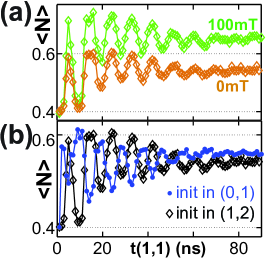
For times shorter than the relaxation time, the curves in Fig. 3(a) show up-turns which are not fully understood. However, high resolution measurements in this region reveal striking oscillations of as a function of the time , as shown in Fig. 4(a). As above, the total cycle time is constant (ns) in a regime, where the signal only depends on (ns fixed). The oscillation period does not vary with magnetic field, but the decay is changed. A purely exponentially decaying function cannot be fitted to the amplitude. Nevertheless it allows to estimate a decay time, which increases monotonically from ns at T to ns at mT.
The oscillations as a function of are robust against variation of the two other waiting times and the total cycle period. The period corresponds to an energy splitting of eV, which is consistent with the energy scales for exchange coupling, hyperfine interaction and spin-orbit interaction (at small fields) in the system Pfund et al. (2007a). These energy scales, the magnetic field dependence of the decay and the selective time dependence on suggest coherent evolution in the subspace as the origin of the oscillations.
A detection of coherent oscillations in the pumping scheme would imply a selective state preparation. In Fig. 4(b) we observe a striking dependence of the phase of the oscillations on the way the two-electron state is loaded. Moving the initial state from to in the charge stability diagram (Fig. 1(b)) results in a phase shift of (in both cases, the charge is pumped in the direction of SB). These observations suggest that the nature and the coupling of spin-states in DQDs are significantly changed by the SOI compared to the well understood situation in GaAs dots.
By pumping single electrons through a spin-blockaded InAs DQD, we studied the dynamics of two coupled spins in the presence of strong SOI. Beyond the spin-selection rules leading to SB, SOI mediated relaxation to the -triplet ground state was observed at finite magnetic field. For times shorter than the relaxation time, oscillations were detected in the pumped current. These processes can influence the operation of two-qubit gates in systems with strong SOI.
Acknowledgements.
We thank B. Altshuler, A. Imamoglu, D. Klauser, D. Loss, C. Marcus, Y. Meir, L. Vandersypen and A. Yacoby for stimulating discussions, M. Borgström and E. Gini for advice in nanowire growth. We acknowledge financial support from the ETH Zurich.References
- Loss and DiVincenzo (1998) D. Loss and D. P. DiVincenzo, Phys. Rev. A 57, 120 (1998).
- Petta et al. (2005) J. R. Petta, A. C. Johnson, J. M. Taylor, E. A. Laird, A. Yacoby, M. D. Lukin, C. M. Marcus, M. P. Hanson, and A. C. Gossard, Science 309, 2180 (2005).
- Johnson et al. (2005) A. C. Johnson, J. R. Petta, J. M. Taylor, A. Yacoby, M. D. Lukin, C. M. Marcus, M. P. Hanson, and A. C. Gossard, Nature 435, 925 (2005).
- Laird et al. (2006) E. A. Laird, J. R. Petta, A. C. Johnson, C. M. Marcus, A. Yacoby, M. P. Hanson, and A. C. Gossard, Phys. Rev. Lett. 97, 056801 (2006).
- Koppens et al. (2006) F. H. L. Koppens, C. Buizert, K. J. Tielrooij, I. T. Vink, K. C. Nowack, T. Meunier, L. P. Kouwenhoven, and L. M. K. Vandersypen, Nature 442, 766 (2006).
- Nowack et al. (2007) K. C. Nowack, F. H. L. Koppens, Y. V. Nazarov, and L. M. K. Vandersypen, Science 318, 1430 (2007).
- Fasth et al. (2007) C. Fasth, A. Fuhrer, L. Samuelson, V. N. Golovach, and D. Loss, Phys. Rev. Lett. 98, 266801 (2007).
- Pfund et al. (2007a) A. Pfund, I. Shorubalko, K. Ensslin, and R. Leturcq, Phys. Rev. B 76, 161308 (2007a).
- Kuemmeth et al. (2008) F. Kuemmeth, S. Ilani, D. C. Ralph, and P. L. McEuen, Nature 452, 448 (2008).
- Burkard and Loss (2002) G. Burkard and D. Loss, Phys. Rev. Lett. 88, 047903 (2002).
- Stepanenko et al. (2003) D. Stepanenko, N. E. Bonesteel, D. P. DiVincenzo, G. Burkard, and D. Loss, Phys. Rev. B 68, 115306 (2003).
- Trif et al. (2007) M. Trif, V. N. Golovach, and D. Loss, Phys. Rev. B 75, 085307 (2007).
- Pothier et al. (1992) H. Pothier, P. Lafarge, C. Urbina, D. Esteve, and M. H. Devoret, Europhys. Lett. 17, 249 (1992).
- Fuhrer et al. (2007) A. Fuhrer, C. Fasth, and L. Samuelson, Appl. Phys. Lett. 91, 052109 (2007).
- Ono et al. (2002) K. Ono, D. G. Austing, Y. Tokura, and S. Tarucha, Science 297, 1313 (2002).
- Pfund et al. (2007b) A. Pfund, I. Shorubalko, K. Ensslin, and R. Leturcq, Phys. Rev. Lett. 99, 036801 (2007b).
- Amasha et al. (2008) S. Amasha, K. MacLean, I. P. Radu, D. M. Zumbuhl, M. A. Kastner, M. P. Hanson, and A. C. Gossard, Phys. Rev. Lett. 100, 046803 (2008).
- Meunier et al. (2007) T. Meunier, I. T. Vink, L. H. W. van Beveren, K.-J. Tielrooij, R. Hanson, F. H. L. Koppens, H. P. Tranitz, W. Wegscheider, L. P. Kouwenhoven, and L. M. K. Vandersypen, Phys. Rev. Lett. 98, 126601 (2007).
- Hanson et al. (2005) R. Hanson, L. H. W. van Beveren, I. T. Vink, J. M. Elzerman, W. J. M. Naber, F. H. L. Koppens, L. P. Kouwenhoven, and L. M. K. Vandersypen, Phys. Rev. Lett. 94, 196802 (2005).
- van der Wiel et al. (2002) W. G. van der Wiel, S. D. Franceschi, J. M. Elzerman, T. Fujisawa, S. Tarucha, and L. P. Kouwenhoven, Rev. Mod. Phys. 75, 1 (2002).
- Koppens et al. (2005) F. H. L. Koppens, J. A. Folk, J. M. Elzerman, R. Hanson, L. H. W. van Beveren, I. T. Vink, H. P. Tranitz, W. Wegscheider, L. P. Kouwenhoven, and L. M. K. Vandersypen, Science 309, 1346 (2005).
- Churchill et al. (2008) H. O. H. Churchill, D. Marcos, F. Kuemmeth, S. K. Watson, and C. M. Marcus, Contribution to INTNAN8 conference (2008).
- Reilly et al. (2008) D. J. Reilly, J. M. Taylor, J. R. Petta, C. M. Marcus, M. P. Hanson, and A. C. Gossard (2008).