Low Loss Metamaterials
Based on Classical Electromagnetically Induced Transparency
Abstract
We demonstrate theoretically that electromagnetically induced transparency can be achieved in metamaterials, in which electromagnetic radiation is interacting resonantly with mesoscopic oscillators rather than with atoms. We describe novel metamaterial designs that can support full dark resonant state upon interaction with an electromagnetic beam and we present results of its frequency-dependent effective permeability and permittivity. These results, showing a transparency window with extremely low absorption and strong dispersion, are confirmed by accurate simulations of the electromagnetic field propagation in the metamaterial.
pacs:
42.70.-a,42.50.Gy,41.20.JbElectromagnetically induced transparency, often abbreviated by EIT, has been proposed as an interface between optical quantum information used for communication and atomic quantum states for information storage Harris-1997 . It is essentially a coherent process observed in three-level atomic media, whose optical response to a laser beam is modified by a second beam with a well-determined detuning Harris-1990 . EIT has been theoretically explained in terms of a dark superposition state with vanishing excitation probability amplitude Imamoglu-1989 ; Lounis-1992 or, alternatively, by destructive quantum interference between different excitation pathways of the excited state Boller-1991 . Due to this process, a small transparency window with significantly enhanced absorption length can be observed in the frequency response of an otherwise opaque medium. At the resonance frequency, the anomalous dispersion profile normally observed for a two-level resonance is transformed into extremely steep normal dispersion. This may slow down light pulses by seven orders of magnitude Kasapi-1995 ; Hau-1999 . More advanced techniques based on EIT even allow for the storage of optical data in matter Fleischhauer-2000 . For a recent review, the reader can consult, e.g., Ref. Fleischhauer-2005 .
EIT has been demonstrated experimentally for several media consisting of an ensemble of non-interacting atomic systems. The first and many recent experiments have been conducted with metal atoms in the gas phase Boller-1991 ; Liu-2001 . Later experimental work was also performed on doped solid-state materials with optically active atomic centers Ham-1997 ; Longdell-2005 and on quantum dot based systems Marcinkevicius-2008 , which have longer coherence times. The experimental handling of these setups is rather hard, since EIT is extremely sensitive to inhomogeneous broadening, e.g., due to the Doppler effect or quantum dot size dispersion; the setups must typically be cooled down to liquid helium temperatures and/or magnetic fields must be applied Phillips-2001 . Recently, a classical equivalent of the EIT was introduced by using coupled optical resonators Xu-2006 and coupled planar fish-scale copper patterns Papasimatis-2008 .
In this Letter, we demonstrate theoretically that electromagnetically induced transparency can be achieved in metamaterials. Such artificially fabricated materials are made up of mesoscopic structured units, on a larger scale than the atomic, but significantly smaller than the wavelength of the interacting radiation. This allows to characterize their electromagnetic properties by their effective permittivity and permeability Smith-2006 . Metamaterials combining negative permittivity and permeability, i.e., negative index materials (NIMs), can be obtained by using tiny electrical circuits called split-ring resonators and continuous wires as the metamaterial’s constituent units Shelby-2001 ; Soukoulis-2006 . Metamaterials have also led to the recently proposed optical invisibility cloaks Pendry-2006 . The main obstacle in realizing NIMs in the visible is dissipation in the magnetic component due to ohmic losses. EIT in metamaterials, and its associated low absorption, may provide a way to overcome this obstacle. In this paper, we shall deal with the metamaterial’s magnetic and electric response, which is the real challenge of the metamaterials field.
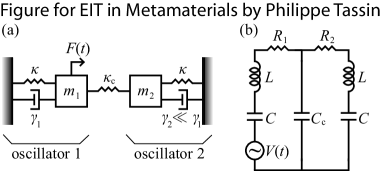
It is known that EIT-like effects are in general not restricted to systems supporting quantum mechanical states and can in principle be observed in classical systems such as plasmas Harris-1996 and coupled microresonators Smith-2004 . However, these system consist of a single element with a pointlike input and output port, and hence cannot be considered as a medium for propagation of electromagnetic waves. The design of the metamaterial proposed here is based on the observation that a simple mechanical system [see Fig. 1(a)], consisting of a driven mass-spring oscillator that is linearly coupled to another oscillator with different dissipation factor, can reproduce an EIT-like absorption dip in its power spectrum GarridoAlzar-2002 . This has been attributed to destructive interference between the normal modes of the mechanical system at the resonance frequency. We start by converting this mechanical model to its equivalent electrical circuit given in Fig. 1(b): a double RLC circuit with inductance and capacitance coupled by a shared capacitor . The two circuits have a different resistance, respectively, and . The power delivered by a sinusoidal voltage source of magnitude to the circuit equals
with . The above power spectrum exhibits an EIT-like response. The dissipation minimum, which occurs approximately at the resonance frequency, can be approximated by if it is assumed that the losses are small (). It will thus suffice to make the second current loop with low enough resistance to obtain a pronounced dissipation minimum in the power spectrum of the circuit. We will take advantage from the fact that the second current loop does not couple to the external field, eliminating the contribution to coming from radiation losses.
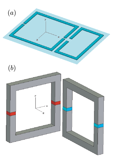
The most straightforward implementation of the double RLC circuit of Fig. 1(b) would be to etch the pattern of a “double” split-ring resonator as depicted in Fig. 2(a) on printed circuit board. Fig. 2a describes a coupled metamaterial design that consists of a ”dark” state (left part) and a ”radiative” state (right part). For perpendicular propagation, the EM wave couples only to the one-gap SRR on the right. So the ”dark” state in this metamaterial is provided by the 2-gap SRR on the left. The coupling between the ”dark” and the ”radiative” state is capacitive (and inductive, to some extent) and can be tuned by changing the distance between the two SRRs. In contrast to atomic EIT, where the coupling between the two energy states is realized by a pump beam, the coupling between the radiative and the dark state in the metamaterial EIT is determined by their spatial separation. The numerical simulations were carried out using the commercial finite integration technique (FIT) software package CST Microwave Studio. For the chosen geometry of Fig. 2a, the resonance frequencyies of the isolated SRRs are equal and around 42.9 THz. The quality factor for the ”dark” state is equal to 120 if calculated from the frequency dependence of the absorption peak and is equal to 800 if calculated from the frequency dependence of the transmission dip. The corresponding values for the ”radiative” SRR are 10 (from the absorption) and 80 (from the transmission). So the quality factor of the ”dark” SRR is an order of magnitude larger than that of the ”radiative” SRR. In Fig. 3a, we present simulation results for the transmission and absorption versus frequency. One can clearly see a dip in the absorption, which is due to classical EIT. In Fig 3b, we present the retrieval results Smith-2006 ; Smith-2002 ; Smith-2005 for the effective dielectric permittivity, , which clearly shows a dip in the imaginary part of , and one can clearly see the really strong dispersion in the frequency dependence of . This strong dispersion with simultaneously low absorption can be used to slow light for a variety of potential applications.
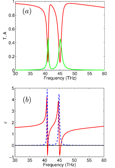
Fig. 2b describes a coupled metamaterial design that responds magnetically and also provides a classical EIT. This design is more difficult to fabricate experimentally, especially at THz and optical frequencies, since it is neccessarily three-dimensional. The propagation direction is along the y-direction and only one SRR can be excited magnetically, because the magnetic field has to have a component perpendicular to the plane of the SRR in order to couple. So the left SRR of Fig. 2b, directly excited by the incident magnetic field, provides the ”radiative” state for the EIT. The other SRR is the ”dark” state and can only be excited due to its coupling to the radiative state. For the chosen geometry of Fig. 2b, the resonance frequencies of the isolated SRRs are equal and around 42.5THz. The quality factor for the ”dark” state is equal to 61 if calculated from the frequency dependence of the absorption peak and is equal to 1200 if calcualted from the frequency dependence of the transmission dip. The corresponding values for the ”radiative” SRR are 42 (from the absorption) and 160 (from the transmission). So the quality factor of the ”dark” state is an order of magnitude larger than that of the ”radiative” SRR. The coupling between the two SRRs is predominantly capacitive (because of the proximity of the gaps) and can be tuned by adjusting the distance between the two SRRs. The coupling splits the reonance of the ”radiative” SRR into two modes with different resonance frequencies. At large separation between the SRRs, where the coupling is weak, the difference between the two resonance frequencies is small, and therefore, the dispersion in between them is very steep. However, the dip in the absorption is very small. The ”radiative” SRR has a broad absorption peak while the ”dark” SRR has a narrow absorption peak. With increasing coupling beween the two SRRs the dip in the absorption spectrum widens and becomes deeper. Simultanoeusly the dispersion becomes more flat.
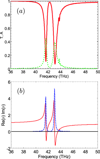
In Fig. 4b, we show the retrieved real and imaginary parts of the magnetic effective permeability for the coupled system of SRRs as shown in Fig. 2b. One clearly sees the classical EIT effect. The imaginary part of has a very low value at 42 THz, which signifies small loss, ocurring simultaneously with a steep dispersion in the real part of . This strong dispersion gives a very large group refractive index (order of 30), see Fig. 5, which can slow the light for many applications.
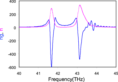
In Fig. 5 we plot the real part of the group index, , versus frequency for the magnetic EIT system shown in Fig. 2b. Notice that becomes really large (of the order of 500) at the two resonance frequencies (41.7 THz and 43.2 THz), of course the losses are tremendous as one can see from Fig. 5. The imaginary part of the index of refraction is large at the two resonance frequencies, but is really small between the frequencies 42 to 43 THz. In this region and the imaginary part of is less than . So the classical EIT system, shown in Fig. 2b, can reduce the group velocity of light by a factor of 30 with low loss. Similar reduction of the group velocity can be obtained for the design shown in Fig. 2a.
In conclusion, we have presented designs of novel metamaterials consisting of quasistatic electric circuits with multiple independent current loops. We have shown that these materials support a dark state leading to a phenomena similar to electromagnetically induced transparency: the metamaterial exhibits a small transmission window with extremely low absorption losses and steep dispersion. No quantum mechanical atomic states are required in this metamaterial to observe the EIT. This could lead to “slow light” applications from the microwave regime up to THz frequencies, where the structure can be most easily fabricated. Furthermore, our classical EIT structures show that the effective parameters are not always associated with high losses. therefore more complex designs, possibly taking advantage of knowledge from quantum optics, could possibly provide a new way to solve the problem of losses in Metamaterials. Our structures already achieves a figure of merit in the transparency window for both the electric permittivity () and the magnetic permeability ().
This work was partially supported by the FW0-Vlaanderen. P. T. thanks the FWO-Vlaanderen for his “Aspirant” fellowship. Work at Ames Laboratory was supported by the Department of Energy (Basic Energy Sciences) under Contract No. DE-AC02-07CH11358. This work was partially supported by the Office of Naval Research (Award No. N00014-07-1-D359) and European Community FET project PHOME (Contract No. 213390).
References
- (1) S.E. Harris, Phys. Today 50, 36 (1997).
- (2) S.E. Harris, J.E. Field, and A. Imamoglu, Phys. Rev. Lett. 64, 1107 (1990).
- (3) A. Imamoglu and S.E. Harris, Opt. Lett. 14, 1344 (1989).
- (4) B. Lounis and C. Cohen-Tannoudji, J. Phys. II (France) 2, 579 (1992).
- (5) K.-J. Boller, A. Imamoglu, and S.E. Harris, Phys. Rev. Lett. 66, 2593 (1991).
- (6) A. Kasapi, M. Jain, G.Y. Yin, and S.E. Harris, Phys. Rev. Lett. 74, 2447 (1995).
- (7) L.V. Hau, S.E. Harris, Z. Dutton, and C.H. Behroozi, Nature (London) 397, 594 (1999).
- (8) M. Fleischhauer and M.D. Lukin, Phys. Rev. Lett. 84, 5094 (2000).
- (9) M. Fleischhauer, A. Imamoglu, and J.P. Marangos, Rev. Mod. Phys. 77, 633 (2005).
- (10) C. Liu, Z. Dutton, C.H. Behroozi, and L.V. Hau, Nature (London) 409, 490 (2001).
- (11) B.S. Ham, M.S. Shahriar, M.K. Kim, and P.R. Hemmer, Opt. Lett. 22, 1849 (1997).
- (12) J.J. Longdell, E. Fraval, M.J. Sellars, and N.B. Manson, Phys. Rev. Lett. 95, 063601 (2005).
- (13) S. Marcinkevicius, A. Gushterov, and J.P. Reithmaier, Appl. Phys. Lett. 92, 041113 (2008).
- (14) D.F. Phillips, A. Fleischhauer, A. Mair, R.L. Walsworth, and M.D. Lukin, Phys. Rev. Lett. 86, 783 (2001).
- (15) Q. Xu, S. Sandhu, M.L. Povinelli, J. Shakya, S. Fan, and M. Lipson, Phys. Rev. Lett. 96, 123901 (2006).
- (16) N. Papasimatis, V.A. Fedotov, N.I. Zheludev, and S.L. Prosvirnin, ”A metamaterial analog of electromagnetic induced transparency”, arXiv: 0801.1485v2 [physics.optics].
- (17) D.R. Smith and J.B. Pendry, J. Opt. Soc. Am. B 23, 391 (2006); Th. Koschny, P. Markoš, E.N. Economou, D.R. Smith, D.C. Vier, and C.M. Soukoulis, Phys. Rev. B 71, 245105 (2005).
- (18) A.A. Shelby, D.R. Smith, and S. Schultz, Science 292, 77 (2001).
- (19) C.M. Soukoulis, M. Kafesaki, and E.N. Economou, Adv. Mater. 18, 1941 (2006).
- (20) J.B. Pendry, D. Schurig, and D.R. Smith, Science 312, 1780 (2006); M. Rahm, D. Schurig, D.A. Roberts, S.A. Cummer, D.R. Smith, and J.B. Pendry, Phot. and Nanostr.: Fund. and Appl. 6, 87 (2008).
- (21) S.E. Harris, Phys. Rev. Lett. 77, 5357 (1996).
- (22) D.D. Smith, H. Chang, K.A. Fuller, A.T. Rosenberger, and R.W. Boyd, Phys. Rev. A 69, 063804 (2004).
- (23) C.L. Garrido Alzar, M.A.G. Martinez, and P. Nussensveig, Am. J. Phys. 70, 37 (2002).
- (24) D.R. Smith, S. Schultz, P. Markoš, and C.M. Soukoulis, Phys. Rev. B 65, 195104 (2002).
- (25) D.R. Smith, D.C. Vier, T. Koschny, and C.M. Soukoulis, Phys. Rev. E 71, 036617 (2005).