Effective interactions of colloids on nematic films
Abstract
The elastic and capillary interactions between a pair of colloidal particles trapped on top of a nematic film are studied theoretically for large separations . The elastic interaction is repulsive and of quadrupolar type, varying as . For macroscopically thick films, the capillary interaction is likewise repulsive and proportional to as a consequence of mechanical isolation of the system comprised of the colloids and the interface. A finite film thickness introduces a nonvanishing force on the system (exerted by the substrate supporting the film) leading to logarithmically varying capillary attractions. However, their strength turns out to be too small to be of importance for the recently observed pattern formation of colloidal droplets on nematic films.
pacs:
82.70.DdColloids and 68.03.Cd Surface tension and related phenomena and 61.30.-vLiquid Crystals1 Introduction
The interactions of colloidal particles trapped at fluid interfaces have been found to differ significantly from the corresponding interactions in bulk solvents. This has been studied mostly for electrically charged particles trapped at interfaces with water. On one hand, the presence of the interface gives rise to direct dipolar electrostatic repulsions between the colloids (see Refs. Pie80 ; Ave02 ; Par07 for some experimental evidence), on the other hand deformations of the interface may induce longer–ranged capillary attractions (briefly reviewed in Refs. Zen06 ; Bre7r ; Oet08 ) which is possibly the source of pattern formation observed in various experiments Ghe97 ; Gar98a ; Que01 ; Gom05 ; Che06 . (See, however, Ref. Fer04 for an alternative explanation due to interface impurities.)
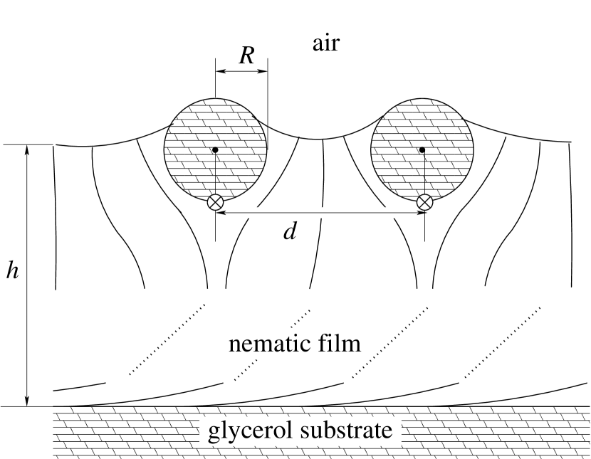
Recently Lav04 ; Lav07 , the experimental observation of ordered structures of glycerol droplets bound to a nematic–air interface has been reported and attributed to an effective pair potential between the colloids which contains a repulsive, elastic part due to director deformations in the supporting nematic film and an attractive, capillary part which is long–ranged and mediated by logarithmically varying deformations of the nematic–isotropic interface caused by the droplets. The schematic setup of this experiment is depicted in Fig. 1. According to Ref. Lav04 , the colloidal particles experience an upward force caused by elastic forces due to director deformations in the supporting nematic film. This upward force on the colloids is supposed to give rise to the aforementioned logarithmically varying interface deformation. Applying a superposition approximation for the deformation field, one can show that the ensuing effective capillary interaction potential between two colloids is likewise varying logarithmically. This is similar to the flotation interaction of mm–sized particles at fluid interfaces for which the force on the colloids is caused by gravity (see, e.g., Ref. Kra00 ) and also parallels the tentative explanation given for the experimentally observed attractions between sub-m charged colloids at a water-oil interface Nik02 (for the controversy around this explanation see Refs. Meg03 ; Nik03 ; For04 ; Kra04 ; Oet05 ; Oet05a ; Kra05 ; Dan06 ).
However, it is now well established Meg03 ; Nik03 ; For04 ; Oet05 ; Oet05a ; Kra05 ; Dom06 that interface deformations and effective colloidal interactions varying logarithmically only arise in experimental systems which are not isolated mechanically. For mechanically isolated systems it can be shown Oet05b ; Wue05 ; Dom05 ; Dom07 that both the interface deformation around a single colloid and the effective interaction between two of them are shorter–ranged and the latter cannot be calculated reliably within the superposition approximation.
In the following we will extend the arguments presented in Refs. Oet05 ; Oet05b ; Wue05 ; Dom05 ; Dom07 to systems with colloids at nematic interfaces. We will show that mechanical isolation of the system “nematic film – colloid – air” can be violated through a subtle interplay between the finite thickness of the film and the anchoring conditions at the colloids and at the nematic interfaces with the substrate and with the air, respectively. However, for experimental conditions as the ones described in Ref. Lav04 a quantitative estimate of the strength of the ensuing logarithmic attraction between the colloids yields that these attractions are unobservably small. Therefore it seems likely that this kind of asymptotic capillary forces cannot be invoked as a relevant mechanism to account for the observations reported in Ref. Lav04 .
The manuscript is organized as follows: In Sec. 2 the coarse–grained model for the nematic phase is introduced which will serve as the basis for all subsequent calculations. In Subsec. 2.1 we study the case of an infinitely thick nematic film. First, we compute the asymptotic form of the director field and the ensuing elastic force between two particles. Then we calculate the effective force arising from the deformation of the fluid–nematic interface caused by the elastic stresses. In Subsec. 2.2 we consider a nematic film of finite thickness, which models more closely the experimental setup described in Ref. Lav04 ; for such a system we extend the above calculations to the two opposite cases of perpendicular and parallel anchoring of the director field at the substrate surface. In Sec. 3 we discuss our results.
2 Coarse–grained model
In view of the mesoscopic length scales involved we describe the bulk part of the nematic free energy associated with the director deformations in terms of the Frank free energy expression within the one–coupling approximation deG74
denotes the volume occupied by the nematic film, is the director field (), and the constant is of the order of N deG74 . The total divergence term in the last line of Eq. (2) exhibits the so–called “–structure” and is unimportant for the bulk equations describing the equilibrium configuration. The surface free energies associated with the interfaces with air and substrate, respectively, (see Fig. 1) are described in terms of the Poulini expression Lav03 :
| (2) |
Here, denotes the local surface normal unit vector pointing outwards from the film or the colloid. Normal alignment is favored for and parallel alignment for . Typically one has N/m Lav03 so that the length scale m is smaller than the range of droplet radii investigated in Ref. Lav04 . Thus, in the “strong anchoring” limit which we shall consider, the effect of the boundary terms is so strong that as a first approximation it amounts to fixing the angle between the director and the surface normal. We shall adopt (normal alignment at the nematic–air interface) and (parallel alignment at the nematic–glycerol interfaces). Some consequences of deviations from the strong anchoring limit will be discussed in App. A.
These surface contributions to the free energy (“wetting energies”) are small corrections to the surface tensions which are mainly due to dispersion interactions. We denote these non–nematic contributions to the surface tensions as (colloid–air surface tension), (substrate–nematic surface tension) and (nematic–air surface tension). Typically, these surface tensions are of the order of N/m. Therefore, they are much larger than the constants which determine the nematic contributions to the surface tension. We see that due to the above anchoring conditions the surface tension of the substrate–nematic interface carries no nematic contributions due to (Eq. (2)) whereas in the strong anchoring limit the full nematic–air surface tension is due to (Eq. (2)).111 A genuine contribution to the surface tension of a nematic interface arises if one takes into account the variation of the nematic tensorial order parameter through the interface, described by, e.g., the Landau–de Gennes free energy functional (generalizing Eq. (2)). The magnitude of these contributions can be estimated by the surface tension of the interface between the nematic and the isotropic phase of a liquid crystal. Typically, such a surface tension is also N/m) and therefore small compared to the dispersion force contribution. Furthermore, a distorted director structure in the bulk may also give rise to surface energy contributions on the boundaries. For an example see Ref. deG74 , p. 131 and p. 174. Also in this case it can be argued that the corresponding contributions to the surface tension do not exceed .
The canonical stress tensor associated with the free energy expression in Eq. (2) is given by
| (3) |
where (summation over ). The total stress tensor is obtained by adding the contribution of the isotropic pressure :
| (4) |
2.1 Macroscopically thick nematic film
First we consider the limiting case (i.e., very thick nematic films (see Fig. 1)).222This was implicitly assumed also by the authors of Ref. Lav04 in discussing Fig. 2 therein. Due to the small values of the elastic coupling constant, , and of the anchoring energy, , the equilibrium configuration of a single colloid at the nematic–air interface deviates only slightly from the reference configuration depicted in Fig. 2. In this latter configuration, the interface is flat and the colloid is positioned such that the contact angle fulfills Young’s law .
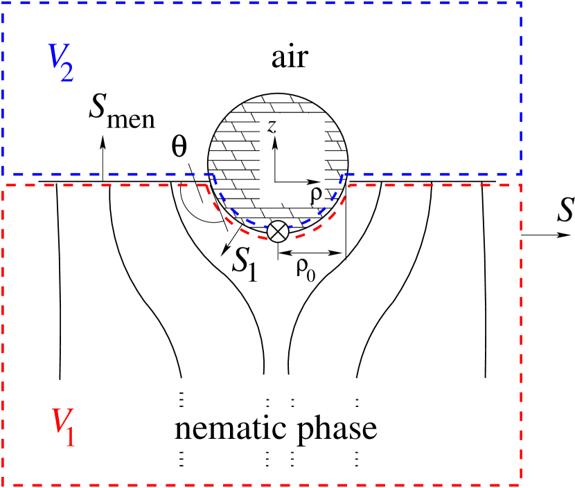
The total force on the whole system reads (the superscript +(-) denotes evaluation on the positive (negative) side of the oriented surface, i.e., on the side the arrows in Fig. 2 [which indicate the surface normals] point to (do not point to)):
| (5) | |||||
In obtaining this equation we have applied Gauss’ theorem. Furthermore we have used the relation in volumina and which is valid because the reference configuration is taken to be in force equilibrium. This also implies that the isotropic pressures above the interface () and below it () are equal and that the director configuration is given by the corresponding Euler–Lagrange equilibrium equations following from the functional in Eq. (2). Since at the interface the colloidal drop is rigidly attached to the liquid crystal, we can identify the vertical force on the colloid and the total force on the air–nematic interface by
| (6) |
and
| (7) |
respectively. Mechanical isolation of the system means that the total force acting on it is zero which leads to
| (8) |
For a given force on the colloid and a given stress on the interface, the interface deformation relative to the reference configuration can be determined perturbatively. To that end, we summarize briefly those results of Ref. Oet05 which are pertinent also for the present system. With the introduction of the two small, dimensionless parameters
| (9) |
one can expand (up to second order in and ) the free energy difference associated with the interface deformation around a single colloid (see Fig. 2) and with a vertical shift which is the difference of the colloid center position relative to that in the reference configuration:
| (10) | |||||
Here, is the capillary length associated with the interface where is the gravitational constant and is the mass density of the nematic phase. This expression for the free energy contains all surface free energy changes relative to the reference configuration involving the interfaces between air, nematic, or colloid. It also contains the contributions due to volume forces acting on the nematic (associated with ) and the energy change of the colloid upon vertical shifts (for further details see Ref. Oet05 ). Note that to leading (quadratic) order in the free energy change of the nematic due to the shifted interface and due to a change in the director configuration with respect to the reference configuration is captured by the term . (The analogous textbook argument for electrostatics Sch98 can be easily generalized to the nematic case described by the free energy expression in Eq. (2).)
Minimizing with respect to and and focussing on the regime yields
| (11) |
with . We see that in the case of an isolated system the logarithmic part of vanishes. The second term on the rhs of Eq. (11) leads to if and thus describes a shorter–ranged power–law decay of the interface deformation.
The absence of logarithmic deformations for an isolated system has been derived here under certain simplifying conditions (small interfacial deformation everywhere, rotational symmetry). In App. B we demonstrate that this conclusion holds in general.
2.1.1 Asymptotic director configuration and elastic force between colloids
In Refs. Pou97 ; Lub98 it has been shown that a colloidal drop immersed in the bulk of a liquid crystal is accompanied by a single counterdefect such that the total topological charge is zero (here, the volume occupied by the colloid contains a topological charge which may be represented by a virtual defect inside the colloid) and the asymptotic behavior of the director field is of dipolar character. Based on similar considerations we shall show that for a colloidal drop located at the air–nematic interface the boundary conditions for that interface impose a quadrupole–like asymptotic behavior of the director field. Macroscopically far from the colloid the director is oriented parallel to the axis. Accordingly, at large but finite distances the director is given by and the bulk free energy corresponding to Eq. (2) is given by
| (12) |
Here we have discarded the total divergence term in the free energy expression (2). It is unimportant for the bulk equations and it adds a mere constant to the free energy because the director is anchored normally at the boundary (the nematic–air interface). Thus for each component the equilibrium director field fulfills the Laplace equation
| (13) |
Analogously to electrostatics, the asymptotic solution for can be expanded in terms of multipoles. To this end we consider the reference configuration in Fig. 2. We choose as the origin of the coordinate system the center of the circle formed by the planar three–phase contact line. The solution for the director field has to fulfill the following requirements: () rotational covariance around the -axis333If specifies the transformation matrix for such a rotation then this requirement is given by . and () . Analyzing the multipole ansatz (with )
| (14) |
it follows that rotational covariance requires , and ( is the Levi-Cività tensor). and are dipole and quadrupole moments, respectively, for a director field of “magnetic” type, i.e., for which holds. The boundary condition () at the interface with the air further imposes and , . It appears to be difficult geometrically to match the asymptotic solution of “magnetic” type with a solution near the colloid which obeys parallel anchoring at the colloid surface. Therefore we discard the magnetic quadrupole, i.e., the leading asymptotic term is given by the remaining, “electric” quadrupole term:
| (15) |
This is at variance with Ref. Lav04 (see Eq. (3) therein and the considerations in the paragraph above that equation which assume a dipole field) but it is consistent with the analysis in Ref. Lub98 . Dimensional analysis yields Lub98 . Note that we have derived the asymptotic behavior of the director field at the interface using strong anchoring at the interface (). In App. A we discuss corrections to strong anchoring which are, however, of subleading character and leave the leading behavior (Eq. (15)) unchanged.
The asymptotic elastic interaction between two colloids in the bulk at distance accompanied by a quadrupolar director deformation has been analyzed in Ref. Ruh97 (for weak anchoring) and in Refs. Ram96 ; Lub98 (using a coarse–graining method, applicable also for strong anchoring) yielding identical results. For the present configuration (distance vector perpendicular to the asymptotic director) the elastic potential is repulsive and varies as
| (16) |
We have used that the dimensionless force parameter is proportional to which actually follows from Eqs. (6), (8), (9), and (17) below. Note that we have simply extrapolated the bulk results for two interacting colloids which cause asymptotically quadrupolar deformations of the director. This appears to be reasonable because the asymptotic director field in the nematic phase for the interface problem is precisely that of the bulk solution in the lower half plane and because the bulk solution is antisymmetric with respect to , thus respecting the boundary condition . However, the precise numerical value of the quadrupole moment might be rather different for the case of the colloid trapped at the interface as compared to the bulk case.
2.1.2 Asymptotic behavior of the stress on the interface and meniscus–induced effective potential between colloids
The asymptotic behavior of the stress tensor component at the interface follows from inserting Eq. (15) into Eq. (3):
| (17) | |||||
(). Consequently the interface deformation around a single colloid for a mechanically isolated system obeys (see Eq. (11)).
For the problem of two identical colloids located at and (vectors are defined in the interface plane ) a distance apart the expression for the free energy is a straightforward generalization of the one for the single–colloid free energy given in Eq. (10):
Here, denotes the force on colloid and is the relative position of its center. The integration domain is the whole interface plane except for the two circular disks bordered by the (reference configuration) contact lines . The meniscus–induced effective potential is the difference between the equilibrium free energy of the two colloids at distance and their free energy at macroscopic distance:
| (19) |
As before, minimization with respect to and renders the equilibrium free energy.
The behavior of has been analyzed in detail in Refs. Oet05 ; Dom07 . Here we summarize these results as far as they are relevant for the present problem. The interfacial stress may be decomposed generally as
| (20) | |||||
Here, denotes the stress around colloid which pertains to the problem of a single colloid. To quadratic order the asymptotic director field around two colloids is given by the superposition of the components of the single–colloid solutions and thus to this order we recover the decomposition in Eq. (20) with the mixed component of stress field given by
| (21) |
It turns out that for a system under an external force the mixed term does not contribute to the leading term in . Thus in the case of a non–vanishing external force this leading contribution to is obtained by a superposition ansatz which consists in approximating the interfacial deformation and the total stress field by the sum of the respective single–colloid quantities only (, ) Oet05 ; Dom07 :
For an isolated system and for the stress given in Eq. (17) the superposition approximation yields as the dominant term. However, this is not the leading term, which rather stems from . This term has two peaks around the colloid centers and therefore close to the colloids it can be approximated by
| (23) |
where . As discussed in Ref. Dom07 , the qualitative behavior of is captured by the integral over :
We note that this form of the mixed stress and thus the leading behavior of is formally analogous to the contributions of the electric field components parallel to the interface in the case of charged colloids Dom07 . The meniscus–induced potential is repulsive and falls off asymptotically444Superficially one would expect a leading decay as displayed in Eq. (23). However, due to the geometric factor in the numerator of Eq. (23), this apparent leading order vanishes upon integration. , as does the likewise repulsive elastic potential . We note that and , so that the meniscus–induced potential is small compared to the elastic one for the parameters of the experiment reported in Ref. Lav04 .
In order to explain the experimentally observed attractions, in Ref. Lav04 a perturbative picture similar to the one presented above was suggested, but the effect of the interface stress was neglected completely. (A similar error has been made in Ref. Nik02 which the authors of Ref. Lav04 refer to.) In a heuristic way, only an “upward” force on the colloid (perpendicular to the interface) associated with the anchoring “wetting” energy at the nematic–particle interface has been invoked in Ref. Lav04 , neglecting the force on the interface described by . In this way, the unbalance of the force gives rise to a logarithmic term in the meniscus deformation and in the meniscus–induced potential. However, mechanical isolation (i.e., force balance) renders the meniscus–induced potential actually repulsive and shorter–ranged (see Eq. (2.1.2)), apparently in contrast to the experimental results. A logarithmically varying potential can only arise if mechanical isolation is violated (see App. B). Below we shall investigate whether a net force on the system “colloid and interface” may appear if the thickness of the nematic phase is finite, as it is the case in the actual experiment.
2.2 Finite thickness of the nematic film
In our discussion of a finite film thickness of the nematic phase we shall consider two cases:
- 1.
-
2.
The anchoring at the bottom substrate surface is parallel (as in the experiment reported in Ref. Lav04 ). At large lateral distances from the colloids, this leads to a director field which gradually rotates from parallel orientation at the bottom substrate to the perpendicular orientation at the upper interface.
For both cases the total force on the system – comprising air, nematic film, colloid, and the substrate – must be zero. This leads to (see Fig. 3(a) and compare with Eq. (5))
For reasons which will become clear in the discussion of the second anchoring case, we consider the isotropic pressures in the substrate and air, and , respectively, not necessarily to be equal to the pressure in the nematic film. The second equation in Eq. (2.2) follows from the equilibrium condition which holds in all volumina.
2.2.1 Perpendicular anchoring at both interfaces
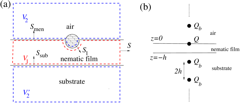
As discussed above, the presence of the colloid asymptotically generates a quadrupolar director field which fulfills the boundary condition at the nematic–air interface. In order to fulfill the boundary condition at the substrate–nematic interface, an image quadrupole of the same strength is needed which, however, leads to a violation of the nematic–air interface boundary condition and requires a second image quadrupole etc. Continuation of this process leads to a string of image quadrupoles as depicted in Fig. 3(b). This string of quadrupoles generates a stress field which vanishes for large lateral distances. Therefore the isotropic pressures must be equal in all volumina: . From Eq. (2.2) one finds that the difference between the force on the colloid and the integrated stress at the nematic–air interface,
| (26) |
is given by the integrated stress over the substrate surface, i.e., the total force on all quadrupoles above the substrate surface exerted by the image quadrupoles in the substrate. Expressed in terms of the force between two quadrupoles at distance , we find
| (27) | |||||
In this equation, the first sum is the total force (divided by ) on the first quadrupole above the substrate exerted by all quadrupoles in the substrate, the second sum is the total force (divided by ) on the second quadrupole above the substrate etc. For the force between two quadrupoles at distance we find, using Eqs. (15), (3), and (26):
| (28) |
Thus mechanical isolation for the system “colloid and nematic–air interface” is violated and the total force on this system is (up to the factor 1.04) given by the quadrupole force . Nevertheless the magnitude of the corresponding induced logarithmic capillary potential (see Eq. (2.1.2) with ) is small, because due to dimensional arguments Lub98 . For parameters similar to the ones appearing in Ref. Lav04 (, ) we find , which is unimportant for the actual intercolloidal interaction.
The elastic potential between two colloids is the interaction between the second quadrupole and the first quadrupole together with its string of image quadrupoles. Using the solution given in Refs. Ram96 ; Ruh97 we have checked that remains repulsive. For the overall magnitude of is somewhat weakened, whereas for a crossover to is observed555This result can be obtained more easily by solving the field equations in cylindrical coordinates rather than by using the image quadrupoles..
2.2.2 Parallel anchoring at the bottom substrate
We assume that the substrate induces a preferred in–plane axis for the director orientation which we take to be the –axis. With no colloid present at the nematic–air interface, the equilibrium director field is given by
| (29) |
with the consequence that both at the nematic–air and at the nematic–substrate interface a constant stress is acting:
| (30) |
For the unperturbed interface to be in equilibrium, the air and substrate pressures differ from the pressure in the liquid crystal: .
We now introduce a single colloid at the nematic–air interface in the reference configuration. Due to this pressure difference, the force on the colloid and the integrated stress over the nematic–air interface are given by (see Eq. (2.2))
| (31) | |||||
| (32) |
and the total excess force on the system “colloid and nematic–air interface” is determined by
| (33) |
In order to calculate the director field and the stress tensor in the presence of the colloid, we introduce the auxiliary director deformation fields and which parametrize the deviations from the unperturbed director field and which are small at large distances from the colloid:
The first equality in Eq. (2.2.2) is a general parametrization of the director field in terms of the auxiliary fields which fulfills . These auxiliary fields are taken to be zero at the substrate and the nematic–air interface, i.e., the boundary conditions are . The nematic free energy of the film up to order is obtained by inserting Eq. (2.2.2) into Eq. (2) for the Frank free energy after dropping the total divergence of the –type. Using the boundary conditions for and we obtain Fuk02 (with the notation introduced in Eq. (3)):
| (35) |
Here, is the free energy of the film without colloid. At first glance it is not evident that this free energy is positive definite. However, the boundary conditions on and ensure positivity Fuk02 . Upon minimization we find , i.e., the deformation field of the director can again be expanded in terms of electrostatic multipoles (Eq. (14)). On the other hand, the solution for must fulfill the Helmholtz equation and can be expanded in terms of multipoles as follows:
where are the spherical Bessel functions of the first [second] kind and are the usual spherical harmonics for the standard set of spherical coordinates . (The origin is again taken as the center of the circular three–phase contact line.) The coefficients are dimensionless multipole moments.
The Dirichlet boundary conditions for and at the two interfaces can be fulfilled as before by constructing the full solution in terms of multipoles around the colloid and corresponding image multipoles as shown in Fig. 3. Since rotational covariance is broken by the parallel substrate anchoring, the solution for contains a nonzero dipole contribution. Nevertheless, the director field still obeys a reflection symmetry with respect to the –plane: and . Therefore, the leading asymptotic behavior for is given by
| (37) |
The dipole contribution should vanish for . If one assumes a power–law dependence on , dimensional analysis for leads to
| (38) |
The precise functional form of turns out to be unimportant for the subsequent calculations. We note that an asymptotic solution with a nonvanishing –component of the dipole moment cannot appear because it would not fulfill the boundary conditions and the reflection symmetry excludes any dipolar contribution in the solution for .666 In this respect the pictorial argument given in Ref. Lav04 (see Fig. 3(b) therein) is slightly misleading (at least in an asymptotic sense): there the assumed director configuration around the colloids for the case of a finite film thickness is a tilted dipole with a nonvanishing component . Actually, the broken symmetry in –direction rather enters through a tilted quadrupole. Therefore the leading asymptotic behavior of takes the form
| (39) | |||||
We note that there are two quadrupolar contributions (with dimensionless moments and ) which show an oscillatory behavior for radial distances (i.e., ). On the other hand, for large film thicknesses there is an intermediate asymptotic regime :
| (40) | |||||
For large film thicknesses the solution for the director field near the nematic–air interface in the regime should coincide with the solution for macroscopically thick films (Eq. (15)). Near the nematic–air interface, one has , . Therefore one recovers the rotationally covariant quadrupole solution of Eq. (15) for (obtained by equating Eq. (37) with Eq. (15) for , i.e., ) and (obtained by equating Eq. (37) with Eq. (15) for , i.e., ). Since and , is a very small number.
The Dirichlet boundary conditions for at the substrate and at the nematic–air interface enforce that the contribution to due to the quadrupole and all corresponding image quadrupoles is zero. This holds also for the contribution of all higher multipoles of degree for which the radial dependence is given by . The only solution of the Helmholtz equation which fulfills the boundary conditions and which, as an additional requirement, is smooth everywhere, is . Since the Bessel functions of the first kind are smooth everywhere, all respective multipole moments must be zero. (This does not hold for the multipole moments pertaining to the Bessel functions of the second kind since is singular at .)
The excess force on the system “colloid and nematic–air interface” follows from Eq. (33) and can be expressed as
| (41) |
utilizing the boundary conditions for the solutions and . For the multipoles appearing in the expansion of the method described in Subsec. 2.2.1 may be used. In order to obtain the quadrupolar contributions to we perform the summation over the image multipoles and the integration over the substrate surface numerically. Due to the slow decay of the stress integral is superficially divergent. However, a detailed asymptotic analysis yields convergence with the result
| (42) |
where has been determined numerically. Note that the linear contribution due to the term in the stress tensor (Eq. (41)) turns out to be zero, as can be easily checked by applying Gauss’ theorem and the field equation . Using the above considerations concerning the magnitude of the multipole moments , and we obtain
| (43) |
where and are numerical coefficients of order 1 and has been defined in Eq. (38). Again the excess force on the colloid falls off rapidly with increasing film thickness such that the induced logarithmic capillary interaction (see Eq. (2.1.2)) remains very weak. For the parameters characterizing the experimental system studied in Ref. Lav04 (, ) we find which appears to be undetectably small. Note that for the direct elastic repulsion remains essentially unchanged because in this regime the leading term of the elastic interaction is given by the repulsion between the two quadrupoles located at the colloid sites. In this case the image quadrupoles can be neglected.
3 Discussion and conclusion
We have investigated the effective potential between two colloidal microspheres of radius floating at asymptotically large distances on an interface between a nematic film of thickness and air (Fig. 1). This effective potential is the sum of an elastic interaction caused by the director distortions around the colloids and of a capillary interaction mediated by surface deformations. We have analyzed the effective potential for large employing the coarse–grained Frank free energy (within the one constant approximation) for the director distortions and the linearized Young–Laplace equation for the interface distortions.
In the case of a macroscopically thick nematic film, the director deformation around a single colloid is of quadrupolar type. Thus the induced elastic interaction between two colloids at distance is repulsive and of quadrupolar type . The capillary interaction is also repulsive and decays but it is much weaker than the elastic interaction. This rapid decay is a consequence of the mechanical isolation of the system, i.e., of the fact that the net force on the colloidal particles and the surrounding interface vanishes.
A finite film thickness leads to a violation of the mechanical isolation of the system “colloid and interface”. (The excess force is counteracted by the film substrate such that the whole experimental system is of course in mechanical equilibrium.) However, on the thermal energy scale the strength of the ensuing logarithmic capillary potential turns out to be very small. In the case of homeotropic boundary conditions on both sides of the nematic film the strength is proportional to (see Eq. (28) and the subsequent discussion). For twisted boundary conditions (parallel at the bottom substrate, perpendicular at the upper nematic–air interface) there is a qualitatively different asymptotic behavior of the director field due to a dipole contribution, which is induced by the broken rotational symmetry and vanishes for . However, even for these boundary conditions the strength of the logarithmically varying capillary potential remains extremely small, vanishing at least (see Eq. (43) and the subsequent discussion).
Thus our analysis based on the mechanical isolation of the experimental system under consideration rules out a significant attractive contribution of capillary type to the effective potential between two colloids at a nematic interface. The amplitude of such a logarithmic contribution vanishes rapidly for large film thickness . Therefore, this effective pair potential does not provide a mechanism for the stability of isolated colloid clusters at a nematic interface as reported in Ref. Lav04 .
Naturally one strives for other explanations for the observation of stable clusters reported in Ref. Lav04 . There the mutual center–to–center distance between neighboring colloids in the cluster has been found to be between and , depending on the radius of the colloids. If the cluster stability is attributed to a minimum in the effective pair potential at this range of distances, the applicability of the above asymptotic considerations at such distances is doubtful for both the elastic and capillary contributions to the effective pair potential:
-
•
Elastic part: For the single–colloid problem, the asymptotic, quadrupolar form of the director field (Eq. (15)) is based on the assumption that the deviations of the director from the preferred direction are small: . At a radial distance from the center of the colloid this implies , which seems to be fulfilled for the dimensional estimate for the quadrupole moment and for the distances under discussion. However, the absolute magnitude of the director deformations is not fixed by these arguments, so that it might be worthwhile to determine the minimum of the Frank free energy by a full numerical calculation in the presence of one or two colloids at the nematic–air interface, similar to Ref. Sta99 where the explicit director solution around a single colloid in the bulk has been determined. Our analysis indicates that only if the multipolar expansion of the director field around a single trapped colloid fails for distances , there is a chance for attractive elastic interactions between two colloids at these distances. Failure of the multipole expansion at these intermediate distances would point to a strong deviation of the magnitude of the multipole moments of order from the dimensional estimate . Thus it is certainly worthwhile to determine multipole renormalizations for bulk and interface configurations, taking into account the full nonlinearity of the director field equations.
-
•
Capillary part: Whenever the colloid–induced nematic stress deviates from the asymptotic, quadrupolar form (Eq. (17)), corrections to the asymptotic capillary potential will arise. However, due to the smallness of the dimensionless force (see Eq. (9), ) the perturbative treatment of the ensuing capillary deformations is justified. Therefore, one of our main findings, i.e., that the magnitude of the capillary potential () is always smaller than the magnitude of the elastic interaction (), is likely to hold also for elastic stresses deviating from the asymptotic limit.
Another possible, subtle effect related to the anisotropy inherent to nematic phases allows the substrate to exert also a torque on the colloidal particles and the surrounding interface. This case can be studied similarly to what we have done here. Actually, the result can be obtained straightforwardly if the analogy of capillary deformation with 2D electrostatics is employed (see, e.g., Ref. Dom06 ): The net force creates “capillary monopoles” with an interaction energy (see Eq. (2.1.2)). A net torque creates “capillary dipoles” and the interaction energy between them is . This decay is sufficiently slow to dominate asymptotically the nematic–mediated repulsion. However, dimensional analysis yields so that the amplitude of this capillary energy, which must vanish for large film thicknesses , has also a too small numerical value to explain the experimental results reported in Ref. Lav04 .
We recall that for simplicity our calculations have been carried out in the “strong anchoring” limit. “Weak anchoring” would lead to a different director field, and thus to different values of the dimensionless forces and (see Eq. (9)). It would also lead to an explicit contribution to the expression (10) for the free energy accounting for the anchoring “wetting” energies (Eq. (2)), which in the “strong anchoring” limit considered so far were subsumed in a (quantitatively negligible) additive renormalization of the surface tensions. The consequences of this more general case of no strong anchoring have to be explored yet, but we do not expect that this alters our conclusion that a logarithmically varying capillary attraction is ruled out by mechanical isolation (), because this latter result is based on very general principles.
Finally we note that for a two–dimensional system, the interactions between two upright circular colloids trapped at the nematic–isotropic interface have been studied numerically Tas05 using a Landau–de Gennes free energy. In three dimensions, this corresponds to long, cylindrical colloids which are aligned side–to–side at the interface. For boundary conditions that yield a similar, quadrupolar behavior of the director field around a single colloid Pet98 , the effective interaction is found to be repulsive and consistent with a power–law decay (for intermediate distance up to 7). In this particular two–dimensional situation, the repulsive interactions appear to be longer–ranged and in the numerical results for the director field there is no trace of a sizeable interface deformation which would lead to capillary attractions.
In summary, we have presented several arguments which rule out an asymptotic attraction of capillary origin in the effective interaction potential between two colloids at a nematic interface. If one discards effective pair potentials as the source of the stability of colloidal mesostructures as the ones found in Ref. Lav04 , the question arises whether this stability is a consequence of genuine many–body effects Lav07a . Nematic surfaces (without colloids) can stabilize regular patterns of surface defects deG74 . If these defects persist in the presence of colloids, the experimentally observed regular order of the colloids might be attributed to them. This issue calls for further experimental and theoretical investigations.
Acknowledgment: We acknowledge useful discussions with S. Chernyshuk, O. Lavrentovich, B. Lev, P. Patrício, and J. M. Romero–Enrique. M. O. thanks the German Science Foundation (DFG) for financial support through the Collaborative Research Centre (SFB-TR6) “Colloids in External Fields”, project section D6-NWG. A. D. acknowledges financial support from the Junta de Andalucía (Spain) through the program “Retorno de Investigadores”.
Appendix A Corrections to the strong anchoring limit
Here we consider the asymptotic director field around a single colloid at the nematic–air interface in the case of finite anchoring strength. For large distances from the colloid, the overall deviations from the preferred director are small and the total free energy of the nematic phase is given by the harmonic approximation for the bulk part (Eq. (12)) and the Poulini expression for the surface part:
| (44) | |||||
The second equation holds because the normal of the nematic–air interface is parallel to the –direction and . For particles with radii in the m range, such as those investigated in Ref. Lav04 , the dimensionless parameter is smaller than 1. Minimizing the free energy renders the Laplace equation in the bulk,
| (45) |
supplemented with the Robin boundary condition:
The general, asymptotic solution is given by the multipole ansatz (Eq. (14))
| (47) |
with the requirement of rotational covariance around the –axis. In view of the boundary condition (Eq. (LABEL:eq:boun)) we note that the derivative in Eq. (LABEL:eq:boun) applied to a multipole of order generates a multipole term of order . Thus, to leading order in , the boundary condition can only be met if the leading multipole () fulfills the strong anchoring condition and is accompanied by a subleading multipole () which is connected to the leading multipole through the condition . Both the monopole and the dipole do not fulfill the strong anchoring condition . Therefore, as before, we find that the multipole expansion starts with the quadrupole solution and that it is necessarily accompanied by a hexapole:
| (48) | |||||
| (49) | |||||
Since , this solution (Eqs. (48)–(LABEL:eq:app_sol2)) exactly satisfies the boundary condition in Eq. (LABEL:eq:boun). Thus the asymptotically dominant director field consists of a quadrupole–hexapole superposition. Furthermore, the magnitude of the accompanying hexapole moment is small due to the factor , therefore the results reported before for strong anchoring (based on the leading quadrupole only) are unaffected by a finite anchoring strength at the nematic–air interface.
Appendix B Force balance in a general configuration
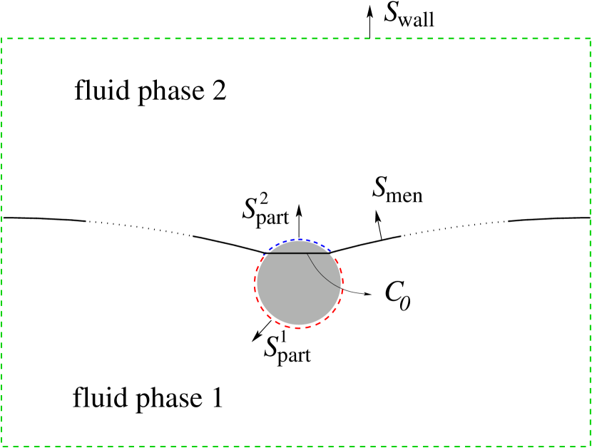
For the benefit of the reader, we discuss in this Appendix some previous results Dom05 ; Dom06 concerning the force balance of a general equilibrium configuration and demonstrate how the amplitude of an asymptotic, logarithmically varying interfacial deformation is determined solely by this mechanical condition of force balance.
Figure 4 represents a colloidal particle in equilibrium at the deformed interface; in general the deformation is not small. The condition of mechanical equilibrium implies that locally the net force on any part of the system must vanish. Thus one has:
-
1.
Each of the fluid phases is in equilibrium. We introduce the forces exerted by each fluid phase on the particle, on the whole fluid meniscus, and on the wall of the container as
(51) (52) (53) respectively, in terms of the stress tensor in each fluid phase with due account for the orientation of the surfaces (see Fig. 4). The superscript 1(2) indicates the lower (upper) phase in Fig. 4. The condition of mechanical equilibrium of each phase under the influence of these three forces reads
(54) The total force exerted by the fluids on the particle is , and on the meniscus it is . The expressions for these forces reduce to those given in Eqs. (6) and (7), respectively, upon evaluation in the reference configuration depicted in Fig. 2.
If the condition of mechanical equilibrium is applied locally to an infinitesimal volume in the bulk of each of the fluid phases, it turns into . In the nematic phase this condition yields the field equations determining the director field.
-
2.
The particle is in mechanical equilibrium under the combined action of and the tension exerted by the interface on the particle at the three–phase contact line . This tension can be expressed in terms of a line integral involving the surface tension :
(55) where is the unit vector tangent to the interface, normal to the contact line, and oriented towards the particle side. Therefore, the condition of mechanical equilibrium reads
(56) -
3.
Any piece of the fluid interface is in mechanical equilibrium. The force on exerted by the fluid phases and the tension exerted on this piece at its boundary, , are balanced:
(57) with oriented towards the exterior of . If this expression is applied locally to an infinitesimal piece of interface, it turns into an equation for the interfacial deformation relating the mean curvature of the interface to the pressure jump accross it. If, in addition, the interface deviates only slightly from a flat interface (identified with the plane ), this equation reduces in turn to the well–known equation (59) below for the local height over the plane .
The net force balance of the whole system follows from the three separate balance conditions (54), (56), and (57): with (so that ; is the three–phase contact line between phase 1, phase 2, and the container enclosing the system), one finds that, as expected, in equilibrium the net force of the outer environment on the system must vanish777The reasoning can be easily generalized to the case that in addition to the short–ranged influence of the wall there are also external fields (gravity, electric force) acting on any part of the system.:
| (58) |
where points to the exterior of the system.
The condition of mechanical equilibrium can be applied advantageously to obtain a precise statement about the amplitude of an interfacial deformation varying logarithmically with the lateral distance from the particle with radius . Far away from the particle, interface deformations and their gradients are small, so that the linearized equation holds. Thus there is a distance beyond which the linear theory is applicable:
| (59) |
where the piece of interface is enclosed by the circle and the line . The general solution to this inhomogeneous Laplace equation can be written as
The fixed values of the constants , , and are determined by the boundary conditions. This expression reduces to Eq. (11) in the particular case of rotational symmetry and a wall located at infinity.
We can apply Eq. (57) to the piece enclosed by the contact line and the circle . Invoking Eq. (56), one has
where the last, approximate equality involves the leading order term in of the line integral. (This approximation is justified because the interface deviates only slightly from a flat interface at the circle .) Evaluating this latter term for the general solution (B) one finally finds that the amplitude of the logarithmic term in Eq. (B) is proportional to the force exerted by the upper and the lower fluid on the particle and on the meniscus:
| (62) |
In obtaining Eq. (62) we have used that in the region (where the interface is almost flat) one has to leading order
| (63) |
In conclusion, if the stress decays sufficiently fast with the distance from the particle, the solution in Eq. (B) will be dominated asymptotically by the logarithm with an amplitude given by Eq. (62), provided this amplitude does not vanish 888To which extent this asymptotic regime is actually observable in a particular experimental realization depends on the precise functional form of and the values of the constant parameters , , and entering the solution given by Eq. (B).. As one can infer from Eq. (54), this latter condition means physically that the walls exert a non-vanishing force: a logarithmic term can only arise if mechanical isolation of the system “colloid + interface” is violated. (Note that Eq. (62) follows actually from Eq. (58) if the interfacial deformations are small.)
We emphasize the generality of this result: it only requires that the interface departs slightly from a flat one for distances sufficiently far from the particle. (Otherwise it is actually not useful to speak of a logarithmically varying deformation to begin with.) In particular, the interfacial deformation close to the particle may be arbitrarily large, the particle itself need not be perfectly spherical, or it may even consist of a many–body configuration lacking any kind of symmetry.
References
- (1) P. Pieranski, Phys. Rev. Lett. 45, 569 (1980).
- (2) R. Aveyard, B. P. Binks, J. H. Clint, P. D. I. Fletcher, T. S. Horozov, B. Neumann, V. N. Paunov, J. Annesley, S. W. Botchway, D. Nees, A. W. Parker, A. D. Ward, and A. N. Burgess, Phys. Rev. Lett. 88, 246102 (2002).
- (3) B. J. Park, J. P. Pantina, E. Furst, M. Oettel, S. Reynaert, and J. Vermant, Langmuir 24, 1686 (2008).
- (4) C. Zeng, H. Bissig, and A. D. Dinsmore, Solid State Comm. 139, 547 (2006).
- (5) F. Bresme and M. Oettel, J. Phys.: Condens. Matter 19, 413101 (2007).
- (6) M. Oettel and S. Dietrich, Langmuir 24, 1425 (2008).
- (7) F. Ghezzi and J. C. Earnshaw, J. Phys.: Condens. Matt. 9, L517 (1997).
- (8) J. Ruiz-García and B. I. Ivlev, Mol. Phys. 95, 371 (1998).
- (9) M. Quesada–Pérez, A. Moncho–Jordá, F. Martínez–López, and R. Hidalgo–Alvarez, J. Chem. Phys. 115, 10897 (2001).
- (10) O. Gómez–Guzmán and J. Ruiz–García, J. Colloid Interface Sci. 291, 1 (2005).
- (11) W. Chen, S. S. Tan, Z. S. Huang, T. K. Ng, W. T. Ford, and P. Tong, Phys. Rev. E 74, 021406 (2006).
- (12) J. C. Fernández–Toledano, A. Moncho–Jordá, F. Martínez–López, and R. Hidalgo–Alvarez, Langmuir 20, 6977 (2004).
- (13) I. I. Smalyukh, S. Chernyshuk, B. I. Lev, A. B. Nych, U. Ognysta, V. G. Nazarenko, and O. D. Lavrentovich, Phys. Rev. Lett. 93, 117801 (2004).
- (14) A. B. Nych, U. M. Ognysta, V. M. Pergamenshchik, B. I. Lev, V. G. Nazarenko, I. Musevic, M. Skarabot, and O. D. Lavrentovich, Phys. Rev. Lett. 98, 057801 (2007).
- (15) P. A. Kralchevsky, K. Nagayama, Adv. Colloid Interface Sci. 85, 145 (2000).
- (16) M. G. Nikolaides, A. R. Bausch, M. F. Hsu, A. D. Dinsmore, M. P. Brenner, C. Gay, and D. A. Weitz, Nature 420, 299 (2002).
- (17) M. Megens and J. Aizenberg, Nature 424, 1014 (2003).
- (18) M. G. Nikolaides, A. R. Bausch, M. F. Hsu, A. D. Dinsmore, M. P. Brenner, C. Gay, and D. A. Weitz, Nature 424, 1014 (2003).
- (19) L. Foret and A. Würger, Phys. Rev. Lett. 92, 058302 (2004).
- (20) K. D. Danov, P. A. Kralchevsky, and M. P. Boneva, Langmuir 20, 6139 (2004).
- (21) M. Oettel, A. Domínguez, and S. Dietrich, Phys. Rev. E 71, 051401 (2005).
- (22) M. Oettel, A. Domínguez, and S. Dietrich, Langmuir 22, 846 (2006).
- (23) K. D. Danov and P. A. Kralchevsky, Langmuir 22, 848 (2006).
- (24) K. D. Danov, P. A. Kralchevsky, and M. P. Boneva, Langmuir 22, 2653 (2006).
- (25) A. Domínguez, M. Oettel, and S. Dietrich, J. Chem. Phys. 128, 114904 (2008).
- (26) M. Oettel, A. Domínguez, and S. Dietrich, J. Phys.: Condens. Matter 17, L337 (2005).
- (27) A. Würger and L. Foret, J. Phys. Chem. B 109, 16435 (2005).
- (28) A. Domínguez, M. Oettel, and S. Dietrich, J. Phys.: Condens. Matter 17, S3387 (2005).
- (29) A. Domínguez, M. Oettel, and S. Dietrich, J. Chem. Phys. 127, 204706 (2007).
- (30) P. G. de Gennes, The Physics of Liquid Crystals (Clarendon, Oxford 1993).
- (31) M. Kleman and O. D. Lavrentovich, Soft Matter Physics: An Introduction (Springer, New York 2003).
- (32) J. Schwinger, L. L. DeRaad Jr., K. A. Milton, and W. Tsai, Classical Electrodynamics (Perseus, Reading 1998), Chap. 11.2.
- (33) P. Poulin, H. Stark, T. C. Lubensky, and D. A. Weitz, Science 275, 1770 (1997).
- (34) T. C. Lubensky, D. Pettey, N. Currier, and H. Stark, Phys. Rev. E 57, 610 (1998).
- (35) R. W. Ruhwandl and E. M. Terentjev, Phys. Rev. E 55, 2958 (1997).
- (36) S. Ramaswamy, R. Nityananda, V. A. Raghunathan, and J. Prost, Mol. Cryst. Liq. Cryst. 288, 175 (1996).
- (37) J. Fukuda, B. I. Lev, K. M. Aoki, and H. Yokoyama, Phys. Rev. E 66, 051711 (2002).
- (38) H. Stark, Eur. Phys. J. B 10, 311 (1999).
- (39) D. Andrienko, M. Tasinkevych, and S. Dietrich, Europhys. Lett. 70, 95 (2005).
- (40) D. Pettey, T. C. Lubensky, and D. R. Link, Liquid Crystals 25, 579 (1998).
- (41) O. Lavrentovich, private communication.