Derivation of a Fundamental Diagram for Urban Traffic Flow
Abstract
Despite the importance of urban traffic flows, there are only a few theoretical approaches to determine fundamental relationships between macroscopic traffic variables such as the traffic density, the utilization, the average velocity, and the travel time. In the past, empirical measurements have primarily been described by fit curves. Here, we derive expected fundamental relationships from a model of traffic flows at intersections, which suggest that the recently measured fundamental diagrams for urban flows can be systematically understood. In particular, this allows one to derive the average travel time and the average vehicle speed as a function of the utilization and/or the average number of delayed vehicles. \PACS 89.40.BbLand transportation and 47.10.abConservation laws and constitutive relations and 51.10.+yKinetic and transport theory of gases
1 Introduction
The study of urban traffic flows has a long history (see Ref. [1] for an overview). For more than a decade now, physicists have contributed various interesting models, ranging from cellular automata [2, 3, 4] to fluid-dynamic approaches [5, 6]. Complementary, one should mention, for example, Refs. [7, 8] as representatives of publications by traffic engineers, and also continuous microscopic flow models used in commercial software tools such as VISSIM.
One research area in traffic physics is the transition from free to congested traffic in urban road networks [9, 10], which started off with the paper by Biham, Middleton and Levine [11]. Interestingly enough, the spreading of congestion seems to share some features with cascading failures [12].
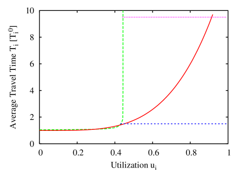
In the following, we will focus on the study of fundamental relationships between flow, utilization, and density on the one hand and the average velocity or travel time on the other hand. Such relationships were already studied in the 60ies [13, 14, 15, 16, 17, 18, 19, 20, 21, 22, 23], but this work primarily took a phenomenological approach. Moreover, the recorded data in the regime of congested road networks scattered enormously. Thus, it was hard to fit a curve. Consequently, many different relationships were proposed. The probably most wide-spread formula is the one published by the Bureau of Public Roads [16]. Accordingly, the travel time of an urban road section with capacity would follow the capacity constraint function
| (1) |
(see Fig. 5). Here, is the arrival flow in that road section and the travel time for light traffic conditions, while and are fit parameters. It is obvious that this formula does not diverge when the capacity is reached, as one may expect. This is just one of the many theoretical inconsistencies of the proposed phenomenological formulas. It is no wonder that the subject of fundamental diagrams for urban traffic has recently been taken up again [24, 25, 26, 27, 28, 29, 30, 31].
The first measurement of an urban fundamental diagram was presented by Godfrey [32]. Ten years later, even Robert Herman and nobel prize laureate Ilya Prigogine addressed traffic flow in cities [33, 34]. They tried to derive fundamental relationships via a statistical physics approach, which however still contained phenomenological elements. Their “two-fluid approach” considered moving and standing traffic and the mutual interdependencies between them.
Recently, the issue of urban gridlock was reanimated by Carlos Daganzo [28]. Together with Geroliminis, he presented convincing evidence for a fundamental diagram of urban traffic flow [29, 30]. Before, fundamental diagrams were mainly used for the study of freeway systems [36]. There, they were very useful to understand capacity effects [1], different traffic states [37], and the traffic dynamics, in particularly the propagation of shock fronts [38]. It is, therefore, not surprising that people are eager to find fundamental relationships for urban traffic as well.
The most recent progress is an approximation of the urban fundamental diagram by Daganzo and Geroliminis, which is based on cutting away parts of the flow-density plane [31]. It appears possible to construct a relationship with kinematic wave theory [35]. In contrast to the density-based approach by Daganzo et al., we will pursue an alternative, utilization-based approach. This is common in queueing theory [39] and transportation planning, where formulas such as the capacity constraint function (1) are used.
After discussing elementary relationships for cyclically signalized intersections of urban road networks in Sec. 2, we will start in Sec. 3 with the discussion of undersaturated traffic conditions and derive a relationship for the average travel time as a function of the utilization or the number of delayed vehicles. Furthermore, we will determine a formula for the average speed. In Sec. 4, we will extend the analysis to congested road conditions, where the intersection capacity is exceeded. Afterwards, in Sec. 5, we will indicate how to deal with oversaturated networks, where the link capacity is insufficient to take up all vehicles that would like to enter a road section. Finally, Sec. 6 provides a summary and discussion. In particularly, we will address issues regarding the transfer of link-based fundamental diagrams to urban areas. We also try to connect the density-based fundamental diagram of Daganzo et al. with the utilization-based approach developed here.
2 Elementary Relationships for Cyclically Operated Intersections
Let us study a single intersection with a periodically operated traffic light. We shall have green phases of duration , during which one or several of the traffic streams are served. shall be 1, if traffic stream is served by green phase , otherwise . The setup time after phase shall require a time period . It may be imagined to correspond to the time period of the amber light (although in practice, this has to be corrected for reaction times and intersection clearing times). The sum of setup times will be called the “lost service time”
| (2) |
while the sum of all green time periods and setup times will be called the “cycle time”
| (3) |
The green times are also sometimes expressed as fractions of the cycle time, i.e.
| (4) |
with . After inserting this into Eq. (3) and rearranging terms, we get
| (5) |
i.e. the cycle time is proportional to the lost service time .
Assuming average inflows per lane, the number of vehicles belonging to traffic stream , which must be served within one cycle time , amounts to . In order to avoid the formation of growing queues (i.e. the onset of congestion), the number of served vehicles per cycle time and lane must reach this value. The number of vehicles of traffic stream potentially served during the green phases is given by per lane, where denotes the outflow capacity (discharge flow) per lane, when stream is served by phase . If we want to have a certain amount of excess capacity to cope with a variability of the inflows, we may demand
| (6) |
with . This linear set of equations may be solved for the green time fractions . In the following, we will assume the case, where not several traffic streams are served in parallel by one and the same green phase, but where each phase serves a single traffic stream . Then, we may assume , if , and otherwise. Furthermore, . With this, Eq. (6) implies
| (7) |
where
| (8) |
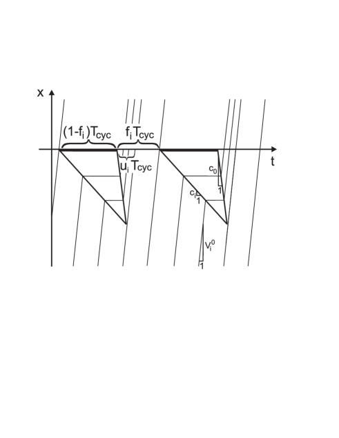
is called the utilization of the service or outflow capacity (see Fig. 1). is a safety factor to cope with variations in the arrival flow (inflow) . According to Eq. (5) we must have
| (9) |
Otherwise, we will have growing vehicle queues from one signal cycle to the next, corresponding to the congested traffic regime.
Note that, at time , the number of vehicles per lane in the road section reserved for traffic stream is given by the time integral of the arrival flow minus the departure flow :
| (10) |
Here, the starting time must be properly chosen to give the correct initial number of vehicles on road section . During the amber and red time periods, we set the permeability , as there is no outflow, while during green phases. The departure flow per lane is given by the service capacity per lane, as long as there is a positive number of delayed vehicles. If represents the characteristic outflow from congested traffic per lane into an area of free flow, the overall service capacity by all service lanes is given by the minimum of the number of lanes used by vehicle stream upstream the intersection, and the number of lanes downstream of it:
| (11) |
When the vehicle queue forming behind a traffic light has completely resolved, the outflow from the road section used by vehicle stream drops from to a lower value. Then, if the greentime period continues, the outflow per lane corresponds to the arrival flow per lane expected at the end of road section under free flow conditions [40]. Here, represents the travel time under free flow conditions, which is obtained by division of the length of the road section reserved for stream by the free speed . Considering also the above definition of the permeabilities reflecting the time-dependent states of the traffic signal, we have
| (12) |
The number of delayed vehicles per lane at time on the road section reserved for vehicle stream can be easily determined as well. In contrast to Eq. (10), we have to subtract the integral of the departure flow from the integral of the arrival flow expected at the end of road section under free flow conditions. Altogether, the number of delayed vehicles can be calculated as
| (13) |
If the traffic flow is organized as a vehicle platoon and the green phase is synchronized with its arrival at the traffic light, the number of delayed vehicles is zero. However, if the traffic flow is uniform, we find
| (14) |
Let us assume that denotes the time when the green phase for traffic stream ended. Then, the next green phase for this traffic stream starts at time , as is the green time period and amounts to the sum of the amber and red time periods. Due to and , is also the time period after which the maximum number of delayed vehicles is reached.
In case of a uniform arrival of vehicles at the rate per lane we have
| (15) | |||||
Since is the rate at which this vehicle queue can be reduced (considering the further uniform arrival of vehicles at rate ), it takes a green time period of
| (16) |
until this vehicle queue is again fully resolved, and newly arriving vehicles can pass the traffic light without any delay.
Finally, let us determine the average delay time of vehicles. If we have a platoon of vehicles which is served by a properly synchronized traffic light, the average delay is . However, if we have a constant arrival flow , the average delay of queued vehicles is given by the arithmetic mean of the maximum delay for the first vehicle in the queue behind the traffic light, which corresponds to the amber plus red time period
| (17) |
and the minimum delay of a vehicle arriving just at the time when the queue is fully dissolved. To get the average delay, we have to weight this by the percentage of delayed vehicles. While the number of vehicles arriving during the cycle time is , the number of undelayed vehicles is given by . Considering formulas (4) and (16), the excess green time is
| (18) |
Hence, the percentage of delayed vehicles is
| (19) |
Altogether, the average delay of all vehicles is expected to be
| (20) |
Inserting Eq. (5) gives
| (21) |
while with Eq. (15) we obtain
| (22) |
Therefore, the average delay time is proportional to the maximum queue length , but the prefactor depends on (or the safety factor , respectively). In case of no excess green time ( and ), we just have
| (23) | |||||
(see Fig. 2).
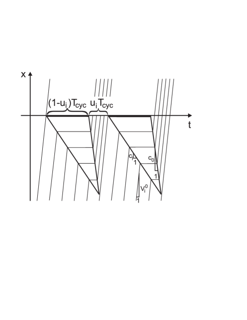
Similarly to the average travel time, we may determine the average queue length. As the average number of delayed vehicles is and a fraction of vehicles is delayed, together with Eqs. (15) and (20) we find
| (24) | |||||
This remarkably simple relationship is known in queuing theory as Little’s Law [39], which holds for time-averaged variables even in the case of non-uniform arrivals, if the system behaves stable (i.e. the queue length is not systematically growing or shrinking). It also allows one to establish a direct relationship between the “average vehicle density”
| (25) |
on the road section used by stream and the utilization , namely
| (26) |
Note that the average density has the same dependencies on other variables as or , and an additional dependency on , i.e. the more natural quantity to use is the queue length .
2.1 Efficiency of Traffic Operation
In reality, the average delay time will depend on the time-dependence of the inflow , and on how well the traffic light is coordinated with the arrival of vehicle platoons. In particular, this implies a dependence on the signal offsets. In the best case, the average delay is zero, but in the worst case, it may also be larger than
| (27) |
see Eq. (20) with . We may, therefore, introduce an efficiency coefficient by the definition
| (28) |
or, considering Eq. (24), equivalently by
| (29) |
For , the traffic light is perfectly synchronized with platoons in traffic stream , i.e. vehicles are served without any delay, while for , the delay corresponds to uniform arrivals of vehicles, when no excess green time is given. If the traffic light is not well synchronized with the arrival of vehicle platoons, we may even have . It also makes sense to define an efficiencies not only for the traffic phases, but also for the operation of a traffic light (i.e. the full cycle). This can be done by averaging over all efficiencies (and potentially weighting them by the number of vehicles arriving in one cycle. Therefore, it makes sense to define the intersection efficiency as
| (30) |
Note that, particularly in cases of pulsed rather than uniform arrivals of vehicles, the efficiencies depend on the cycle time and, therefore, also on the utilizations . Increasing the efficiency for one traffic stream will often (but not generally) reduce the efficiency of another traffic stream , which poses a great challenge to traffic optimization.
The exact value of the efficiency depends on many details such as the time-dependence of the arrival flow and its average value , the length of the road section, and the signal control scheme (fixed cycle time or not, adaptive green phases or not, signal offsets, etc.). These data and the exact signal settings are often not fully available and, therefore, it is reasonable to consider as fit parameters rather than deriving complicated formulas for them. Nevertheless, we will demonstrate the general dependence on the utilization in the following.
For this, we will study the case of excess green times (), which are usually chosen to cope with the stochasticity of vehicle arrivals, i.e. the fact that the number of vehicles arriving during one cycle time is usually fluctuating. The choice , i.e. , also implies
| (31) |
This reflects the well-known observation that the average departure flow usually does not reach the value given by the green time fraction times the saturation flow .
The efficiency related with a value may be derived from Eqs. (21) and (28). We obtain
| (32) |
where according to Eq. (7). The efficiency is usually smaller than in the case, where the traffic light is turned red as soon as a vehicle queue has been dissolved (for exceptions see Ref. [41]). Then, for . Formula (32) also allows one to treat the case where the green time fractions and the cycle time are not adapted to the respective traffic situation, but where a fixed cycle time and fixed green time fractions are implemented. This corresponds to constant green times
| (33) |
In case of uniform vehicle arrivals, we just have to insert the corresponding value into Eq. (32) to obtain . In the case of non-uniform arrivals, can be understood as fit parameter of our model, which allows us to adjust our formulas to empirical data and to quantify the efficiency of traffic light operation. In this way, we can also absorb effects of stochastic vehicle arrivals into the efficiency coefficients , which simplifies our treatment a lot.
3 Fundamental Relationships for Undersaturated Traffic
The travel time is generally given by the sum of the free travel time and the average delay time , where denotes the length of the road section used by vehicle stream and the free speed (or speed limit). With Eq. (24), we get
| (34) |
Inserting Eq. (29), we can express the travel time solely in terms of the utilization , and we have
| (35) |
The formula (35) constitutes a fundamental relationship between the average travel time on the capacity utilization under the assumptions made (mainly cyclical operation with certain efficiencies ). Of course, one still needs to specify the factor . In case of constant arrival rates , this factor is given by Eq. (32), which finally results in
| (36) |
After insertion of Eq. (7), we get
| (37) |
Sometimes, it is desireable to express the fundamental relationships in terms of the density rather than the utility. Inserting Eq. (35) into , and this into Eq. (26), we obtain the equation
| (38) |
which can be numerically inverted to give the utilization as a function of the scaled densities . The calculations are simpler in case of a fixed cycle time and an uniform arrival of vehicles. By inserting Eq. (20) into (26) [and with , , see Eq. (33)], we get
| (39) | |||||
which finally yields
| (40) |
This can be inserted into Eq. (26) to give
| (41) | |||||
3.1 Transition to Congested Traffic
The utilizations increase proportionally to the arrival flows , i.e. they go up during the rush hour. Eventually,
| (42) |
which means that the intersection capacity is reached. Sooner or later, there will be no excess capacities anymore, which implies and . In this case, we do not have any finite time periods , during which there are no delayed vehicles and where the departure flow agrees with the arrival flow . Therefore, according to Eq. (12), and certain relationships simplify. For example, the utilization is given as integral of the permeability over one cycle time , divided by the cycle time itself:
| (43) |
Moreover, in the case of constant in- and outflows, i.e. linear increase and decrease of the queue length, the average number of delayed vehicles is just given by half of the maximum number of delayed vehicles:111Note that the formulas derived in this paper are exact under the assumption of continuous flows. The fact that vehicle flows consist of discrete vehicles implies deviations from our formulas of upto 1 vehicle, which slightly affects the average travel times as well. In Fig. 2, for example, the number of vehicles in the queue is rather than . Therefore, the related maximum delay time is , which reduces the average delay time by .
| (44) |
As a consequence, we have
| (45) |
The average speed of traffic stream is often determined by dividing the length of the road section reserved for it by the average travel time , which gives
| (46) |
and can be generalized with Eq. (28) to cases with an efficiencies :
| (47) |
Note, however, that the above formulas for the average speed are implicitly based on a harmonic rather than an arithmetic average. When correcting for this, Eq. (46), for example, becomes
| (48) |
As is shown in Appendix A, this has a similar Taylor approximation as the harmonic average (47). The latter is therefore reasonable to use, and it is simpler to calculate.
As expected from queuing theory, the average travel time (45) diverges, when the sum of utilizations reaches the intersection capacity, i.e. . In this practically relevant case, the traffic light would not switch anymore, which would frustrate drivers. For this reason, the cycle time is limited to a finite value
| (49) |
where typically . This implies that the sum of utilizations must fulfill
| (50) |
As soon as this condition is violated, we will have an increase of the average number of delayed vehicles in time, which characterizes the congested regime discussed in the next section.
4 Fundamental Relationships for Congested Traffic Conditions
In the congested regime, the number of delayed vehicles does not reach zero anymore, and platoons cannot be served without delay. Vehicles will usually have to wait several cycle times until they can finally pass the traffic light. This increases the average delay time enormously. It also implies that there are no excess green times, which means . Consequently, we can also assume , as long as the outflow from road sections during the green phase is not (yet) obstructed (otherwise see Sec. 5). Formula (13) applies again and implies for time-independent arrival flows
| (51) | |||||
where
| (52) |
is the green time fraction of the cycle time reserved for vehicle stream . Therefore, the number of delayed vehicles grows by an amount in each cycle time . The minimum number during one cycle is
| (53) |
and considering Eq. (15), the maximum number of delayed vehicles is
| (54) |
Because of and , the average number of delayed vehicles is
| (55) | |||||
Obviously, the average density
| (56) | |||||
is obtained by dividing the previous formula by .
It seems logical to use Eq. (55) to determine the average delay time as
| (57) | |||||
However, this turns out to be not correct, as some of this time is actually not lost, but used to move forward (see Fig. 3). After this first simple analysis, we need to look at the problem more carefully, and perform the calculation without the use of Eq. (24), as Little’s Law is not applicable in case of non-stable, systematically growing queues.
Again, we apply the fact that the number of vehicles arriving in one cycle is , while the number of vehicles served during one green time period of duration is given by . The difference of both numbers is added to the growing vehicle queue. The quotient of the number of vehicles arriving in cycles and the number of vehicles served during one green time period, when rounded down, corresponds to the number of additional stops needed by newly arriving vehicles. Therefore, with we have
| (58) |
Here, represents the floor function rounding to lower integers (i.e. cutting the digits after the period, if ). Assuming that is the time at which congestion sets in, Eq. (58) can be generalized to continuous time , allowing us to estimate the number of additional stops of a vehicle arriving at time :
| (59) |
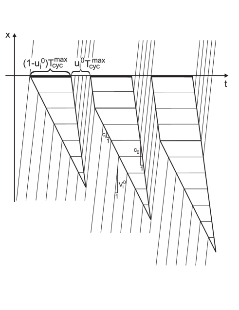
As Fig. 3 shows, the delay time by each of the additional stops is . Moreover, we can see that the triangular part of the vehicle queue in the space-time plot gives a further contribution to the delay time of vehicles. Applying Eq. (20) with , the average time delay in this triangular part is , i.e. the arithmetic average between zero and the sum of the red and amber time period (amounting to ). In summary, the delay time of a newly arriving vehicle at time (when averaging over the triangular part for the sake of simplicity), is
| (60) | |||||
Accordingly, the average travel time does not only grow with time (or the number of cycles passed), it also grows stepwise due to the floor function .
When we also average formula (60) over its steps, we obtain the approximate relationship
| (61) | |||||
where it is important to consider that the floor function is shifted by with respect to the function , which rounds to the closest integer: . Moreover, when averaging over the last (st) cycle we get
| (62) |
It is also possible to replace the dependence on the number of cycles by a dependence on the average density of delayed vehicles by applying Eq. (55). In this way, we obtain
| (63) |
Therefore, while in Sec. 3 we could express the average travel time and the average velocity either in dependence of the average density or the utilization alone, we now have a dependence on both quantities.
Finally note that Eqs. (60) to (62) may be generalized to the case where the arrival rate of vehicles is not time-independent. This changes the triangular part of Fig. 3. In order to reflect this, the corresponding contribution may, again, be multiplied with a prefactor , which defines an efficiency . While corresponds to the previously discussed case of an uniform arrival of vehicles, reflects the case where a densely packed platoon of vehicles arrives at the moment when the last vehicle in the queue has started to move forward.
5 Fundamental Relationships for Oversaturated Traffic Conditions
We have seen that, under congested conditions, the number of delayed vehicles is growing on average. Hence, the vehicle queue will eventually fill the road section reserved for vehicle stream completely. Its maximum storage capacity per lane for delayed vehicles is
| (64) |
where denotes the maximum density of vehicles per lane. The road section becomes completely congested at the time
| (65) |
when according to Eq. (53) reaches the value , which implies
| (66) |
where
| (67) |
see Eq. (53). The number of stops is given by Eq. (59). See Fig. 4 for an illustration.
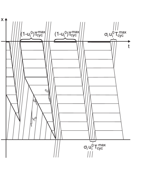
Complete congestion causes spillover effects and obstructs the arrival of upstream vehicles, even though the green phase would, in principle, allow them to depart. When these spill-over effects set in, we are in the over-saturated regime, and only a certain fraction of the green phase of duration can be used, where . Note that decreases in time as the number of blocked subsequent road sections grows. This may eventually lead to gridlock in a large area of the urban traffic system.
In the case , must essentially be replaced by in the fundamental relationships for congested traffic, and the lost service time becomes
| (68) |
That is, the reduced service time may be imagined like an extension of the amber time periods. Therefore, it would make sense to reduce the cycle time to a value in the oversaturated regime.
Note, however, that the travel times on the road section reserved for stream are not growing anymore, because the road section is limited to a length . This allows us to determine the corresponding travel time on the link as follows: The number of vehicles served per cycle time is . For this reason, the average travel time can be estimated as
| (69) |
and the average delay time as
| (70) |
Note that these values are now independent of both, the utilization and the average density, as soon as the latter assumes the value , corresponding to a fully congested road section.
5.1 Transition from Oversaturated to Undersaturated Traffic Conditions
If the arrival flow after the rush hour drops below the value of , the vehicle queue will eventually shrink, and the road section used by vehicle stream enters from the oversaturated into the congested regime. The formulas for the evolution of the number of delayed vehicles are analogous to Eqs. (53) and (54). The queue length starts with and is reduced by in each cycle of length . Counting the number of cycles since the re-entering into the congested regime by , we have
| (71) |
and considering Eq. (15), the maximum number of delayed vehicles is
| (72) |
As soon as reaches zero, the road section used by vehicle stream enters the undersaturated regime. Before, the number of stops of vehicles joining the end of the vehicle queue are expected to experience an number of stops with
| (73) |
compare Eq. (58).
6 Summary and Outlook
Based on a few elementary assumptions, we were able to derive fundamental relationships for the average travel time and average velocity . These relationships are functions of the utilization of the service capacity of a cyclically signalized intersection and/or the average number of delayed vehicles (or the average density of vehicles in the road section of length reserved for traffic stream ). We found different formulas, (1) for the undersaturated regime, (2) for the congested regime, and (3) for the oversaturated regime. While we also discussed situations, where fixed cycle times are applied, we primarily focussed on situations, where the cycle time is adjusted to the utilization (in the undersaturated regime) and to the effectively usable green time fraction (in the oversaturated regime). Our results are summarized in Fig. 5), where also a comparison with the capacity restraint function (1) is made.
The formulas for the non-congested regime can be either expressed as non-trivial functions of the utilization or the average queue length (or the average density ). They contain a fit parameter , which reflects effects of variations in the arrival flow and relates to the efficiency of traffic signal operation in terms of synchronizing with vehicle platoons. In the best case, delay times are zero, which shows the great optimization potential for traffic control in this regime.
In the congested regime, the number of delayed vehicles grows in time, and the majority of vehicles is stopped several times by the same traffic light. Therefore, the average travel time does not only depend on the utilization , but also on the average vehicle queue (or the average density ). Although the traffic light control can still improve the average travel times by synchronizing with the arrival of vehicles, the related efficiency effect is rather limited.
In the oversaturated regime, the storage capacity of the road section is fully occupied by delayed vehicles, which obstructs the arrival flow. Therefore, the average travel time of a road section reaches a constant maximum value. Nevertheless, the travel time of vehicles increases further in time due to spillover effects, which trigger the spreading of congestion to upstream road sections. The actually usable fraction of the green time period is described by a parameter . Synchronization can still reach some improvements. The most favorable control is oriented at a fluent upstream propagation of the little remaining free space (the difference between and ). That is, rather than minimizing the delay of downstream moving vehicle platoons, one should now minimize the delay in filling upstream moving gaps [42]. Furthermore, note that the free travel time and the delay time in the oversaturated regime are proportional to the length of the road section, while the delay times in the undersaturated and congested regimes are independent of .
Based on the above results, it is obvious that it cannot be very successful to describe the travel time of a link by a capacity restraint function which depends on only. This basically means an averaging over data that, in principle, are also dependent on the average queue length (or on the time passed since the onset of congestion). It is, therefore, no wonder that empirical data of travel times as a function of the utilization scatter so enormously in the congested and oversaturated regimes (see e.g. Ref. [27]), that a fitting of the data to functional dependencies of any kind does not make much sense.
This has serious implications for transport modeling, as capacity restraint functions such as formula (1) are used for modeling route choice and, hence, for traffic assignment. Based on the necessary revision of this formula and comparable ones, all traffic scenarios based on these formulas should be critically questioned. Given the computer power of today, it would not constitute a problem to perform a dynamic traffic assignment and routing based on the more differentiated formulas presented in this paper.
6.1 Transferring the Link-Based Urban Fundamental Diagrams to an Area-Based One
We may finally ask ourselves, whether the above formulas would also allow one to make predictions about the average travel times and speeds for a whole area of an urban traffic network, rather than for single road sections (“links”) only. This would correspond to averaging over the link-based fundamental diagrams of that area. For the sake of simplicity, let us assume for a moment that the parameters of all links would be the same, and derive a velocity-density diagram from the relationship (85) between average vehicle speed and the capacity utilization . Taking into account and dropping the index , we can write
| (74) |
with . The cycle time
| (75) |
follows from Eq. (5), assuming signal phases with for simplicity. Note that the previous formulas for denote the average density of delayed vehicles, while the average density of all vehicles (i.e. delayed and freely moving ones) is given by
| (76) |
where denotes the average number of vehicles on a road section of length . Plotting over finally gives a speed-density relationship .
We have now to address the question of what happens, if we average over the different road sections of an urban area. Considering the heterogeneity of the link lengths , efficiencies , utilizations , and densities , one could think that the spread in the data would be enormous. However, a considerable amount of smoothing results from the fact that in- and outflows of links within the studied urban area cancel out each other, and it does not matter whether a vehicle is delayed in a particular link, or in the previous or subsequent one. Therefore, the resulting fundamental diagrams for urban areas are surprisingly smooth [29, 30]. The details of the curves, however, are expected to depend not only on the average density, but also on the density distribution, the signal operation schemes, and potentially other factors as well.
When averaging over different links, we have to study the effects of the averaging procedure on the density and the speed. The density just averages linearly: Thanks to Little’s law [39], the formula (76) can also be applied to an urban area, as long as the average number of vehicles in it is stationary. However, as the link-based fundamental diagram between the flow and the density is convex, evaluating the flow at some average density overestimates the average flow.222When averaging over speed values, they have to be weighted by the number of vehicles concerned, i.e. by the density. This comes down to determining an arithmetic average of the flow values and dividing the result by the arithmetic average of the related densities. Hence, an overestimation of the average flow also implies an overestimation of the average velocity. However, considering the curvature of and knowing the variability of the density allows one to estimate correction terms. This also implies that, when the relationship is transferred from single links to urban areas, the average speed is overestimated for a given density, as Ref. [31] has shown.
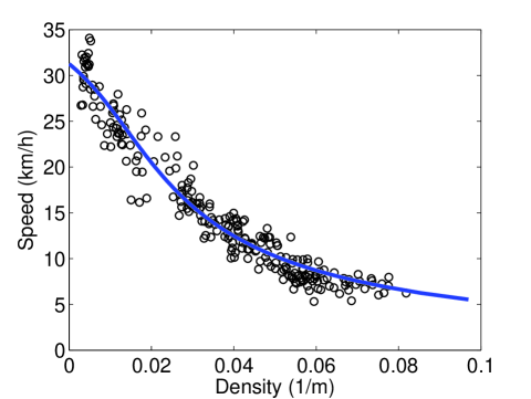
Despite this expected deviation in heterogeneous and inhomogeneously used road networks, and despite the many other simplifications, the curve fits empirical data of the speed-density relation in an urban area quite well. Figure 3 displays empirical data obtained for the center of Yokohama [29] together with a fit of the theoretical speed-density relationship , where only the three parameters , , and were adjusted. Surprisingly, the effects of network interactions could be sufficiently well represented by a single parameter , which relates to the efficiency of road sections according to Eq. (32). This approximation seems to work in situations close enough to a statistical equilibrium (when the number of vehicles in the urban area does not change too quickly).
In contrast, for an understanding of the spreading dynamics of congestion patterns, we expect that one must study the interaction between the flow dynamics and the network structure. This difficult subject goes beyond the scope of this paper and beyond what is doable at the moment, but it will be interesting to address it in the future.
The author thanks for an inspiring presentation by Carlos Daganzo, for useful comments by Stefan Lämmer, and intresting discussions with Nikolas Geroliminis, who was also kind enough to provide the empirical data from the center of Yokohama displayed in Fig. 6, see Fig. 7 in Ref. [29]. He extracted these from original data of GPS-equipped taxis by Prof. Masao Kuwahara from the University of Tokyo. The fit of the theoretically predicted relationship to the empirical data was carried out by Anders Johansson. Furthermore, the author is grateful for partial support by the Daimler-Benz Foundation Project 25-01.1/07 on BioLogistics, the VW Foundation Project I/82 697, the NAP project KCKHA005 “Complex Self-Organizing Networks of Interacting Machines: Principles of Design, Control, and Functional Optimization”, and the ETH Competence Center ’Coping with Crises in Complex Socio-Economic Systems’ (CCSS) through ETH Research Grant CH1-01-08-2.
References
- [1] D. C. Gazis, Traffic Theory (Kluwer Academic, Boston, 2002).
- [2] J. Esser and M. Schreckenberg, Microscopic simulation of urban traffic based on cellular automata. Int. J. Mod. Phys. B 8, 1025–1036 (1997).
- [3] P. M. Simon and K. Nagel, Simplified cellular automaton model for city traffic. Phys. Rev. E 58, 1286–1295 (1998).
- [4] K. Nagel, Multi-Agent Transportation Simulations, see http://www2.tu-berlin.de/fb10/ISS/FG4/archive/sim-archive/publications/book/
- [5] M. Hilliges and W. Weidlich, A phenomenological model for dynamic traffic flow in networks. Transpn. Res. B 29, 407–431 (1995).
- [6] D. Helbing, J. Siegmeier, and S. Lämmer, Self-organized network flows. Networks and Heterogeneous Media 2, 193–210 (2007).
- [7] M. Cremer and J. Ludwig, A fast simulation model for traffic flow on the basis of Boolean operations. Math. Comput. Simul. 28, 297ff (1986).
- [8] C. F. Daganzo, The cell transmission model. II: Network traffic. Transpn. Res. B 29 (1995), 79–93 (1995).
- [9] T. Nagatani, Jamming transition in the traffic-flow model with two-level crossings. Phys. Rev. E48, 3290-3294 (1993).
- [10] D. Chowdhury and A. Schadschneider, Self-organization of traffic jams in cities: Effects of stochastic dynamics and signal periods. Phys. Rev. E 59, R1311–R1314 (1999).
- [11] O. Biham, A. A. Middleton, and D. Levine, Self-organization and a dynamical transition in traffic-flow models. Phys. Rev. A 46, R6124–R6127 (1992).
- [12] J.-F. Zheng, Z.-Y. Gao, and X.-M. Zhao, Modeling cascading failures in congested traffic and transportation networks. Phys. Stat. Mech. Appl. 385, 700–706 (2007).
- [13] N. A. Irwin, M. Dodd, and H. G. Von Cube, Capacity restraint in multi-travel model assignment programs. Highway Research Board Bulletin 347, 258–289 (1961).
- [14] R. J. Smock, An iterative assignment approach to capacity restraint on arterial networks, Highway Research Board Bulletin 347, 60–66 (1962).
- [15] W. W. Mosher, A capacity restraint algorithm for assignment flow to a transport network. Highway Research Record 6, 41–70 (1963).
- [16] Bureau of Public Roads, Traffic Assignment Manual (U.S. Dept. of Commerce, Urban Planning Division, Washington, D.C., 1964).
- [17] T. J. Soltmann, Effects of alternate loading sequences on results from Chicago trip distribution and assignment model. Highway Research Record 114, 122–140 (1965).
- [18] K. B. Davidson, A flow travel-time relationship for use in transportation planning. In: Proceedings of the 3rd ARRB Conference, Part 1 (Australian Road Research Board, Melbourne, 1966), pp. 183–194.
- [19] R. J. Smeed, Road capacity of city centers. Traffic Engineering and Control 8, 455–458 (1966).
- [20] K. R. Overgaard, Urban transportation planning traffic estimation. Traffic Quarterly, 197–218 (1967).
- [21] J. M. Thomson, Speeds and flows in central London: 2. Speed-flow relations. Traffic Engineering and Control 8, 721–725 (1967).
- [22] J. G. Wardrop, Journey speed and flow in central urban areas. Traffic Engineering and Control 9, 528–532 (1968).
- [23] Y. Zahavi, Traffic performance evaluation of road networks by the -relationship, Parts I and II. Traffic Engineering and Control 14, 228–231 and 292–293 (1972).
- [24] R. Akcelik, Travel time functions for transport planning purpose: Davidson’s function, it’s time-dependent form and an alternative travel time function. Australian Road Research 21, 49–59 (1991).
- [25] K. M. Lum, H. S. L. Fan, S. H. Lam, and P. Olszewski, Speed-flow modeling of arterial roads in Singapore. J. Transpn. Eng. 124, 213–222 (1998).
- [26] H. M. Zhang, Link-journey-speed model for arterial traffic. Transpn. Res. Rec. 1676, 109–115 (1999).
- [27] H. Tu, Monitoring Travel Time Reliability on Freeways (Ph.D. thesis, Delft University of Technology, 2008).
- [28] C. F. Daganzo, Urban gridlock: Macroscopic modeling and mitigation approaches, Transport. Res. B 41(1), 49-62 (2007).
- [29] N. Geroliminis and C. F. Daganzo, Existence of urban-scale macroscopic fundamental diagrams: Some experimental findings. Transpn. Res. B 42, 759–770 (2008).
- [30] N. Geroliminis and C. F. Daganzo, Macroscopic modeling of traffic in cities. TRB 86th Annual Meeting, Paper #07-0413, Washington D.C. (2007).
- [31] C. F. Daganzo and N. Geroliminis, An analytical approximation for the macroscopic fundamental diagram of urban traffic. Accepted for publication (2008).
- [32] J. W. Godfrey, The mechanism of a road network. Traffic Engineering and Control 11(7), 323–327 (1969).
- [33] R. Herman and I. Prigogine, A two-fluid approach to town traffic. Science 204, 148–151 (1979).
- [34] R. Herman and S. Ardekani, Charakterizing traffic conditions in urban areas. Transportation Science 18(2), 101-139 (1984).
- [35] M. Eichler and C. F. Daganzo, Bus lanes with intermittend priority: Strategy formulae and an evaluation. Transportation Research B 40(9), 731–744 (2006).
- [36] D. Helbing, Traffic and related self-driven many-particle systems. Reviews of Modern Physics 73, 1067-1141 (2001).
- [37] D. Helbing, M. Treiber, A. Kesting, and M. Schönhof, Theoretical vs. empirical classification and prediction of congested traffic states, European Physical Journal B, submitted (2008).
- [38] G. B. Whitham, Linear and Nonlinear Waves (Wiley, New
- [39] R. Hall, Queueing Methods for Service and Manufacturing (Prentice Hall, Upper Saddle River, NJ, 1991). York, 1974).
- [40] D. Helbing, A section-based queueing-theoretical traffic model for congestion and travel time analysis in networks. Journal of Physics A: Mathematical and General 36, L593-L598 (2003).
- [41] D. Helbing, Operation regimes and slower-is-faster effect in the control of traffic intersections. European Journal of Physics B, submitted (2008).
- [42] D. Helbing, T. Seidel, S. Lämmer, and K. Peters, Self-organization principles in supply networks and production systems, in: Econophysics and Sociophysics, edited by B. K. Chakrabarti, A. Chakraborti, A. Chatterjee (Wiley, Weinheim, 2006), p. 552.
Appendix A Determination of Average Travel Times and Velocities
Let be a function and a weight function. Then, the average of the function between and is defined as
| (77) |
In case of uniform arrivals of vehicles, we have a functional relationship of the form for the travel time, and the weigth function is constant, i.e. . Here, , , and . With and , the formula for the average travel time becomes
| (78) |
where we have used . Inserting the above parameters, we obtain the previously derived result
| (79) |
When determining the average velocity , the function to average over is of the form , where and the other parameters are as defined before. We use the relationship
| (80) | |||||
Dividing this again by the normalization factor and inserting the above parameters finally gives
| (81) |
where we have used . This formula corrects the naive formula
| (82) |
where we have used . Therefore, the above Taylor approximations of both formulas agree, but higher-order approximations would differ. The formulas in the main part of the paper result for , which corresponds to the case (i.e. ).
Generalizing the above approach to the case , we must split up the integrals into one over extending from to and another one over from to , where the specifications of , , and are unchanged. Taking into account , this gives
| (83) |
where
| (84) |
Considering Eq. (15), we get
| (85) |
In second-order Taylor approximation, this results in
| (86) |
which can also be derived from Eq. (82), considering Eq. (15) and the percentage of delayed vehicles, which is given by Eq. (19). The same result follows from
| (87) |
together with Eq. (21).