Dynamical Regimes Induced by Spin Transfer in Magnetic Nanopillars.
Abstract
We demonstrate the predicted out-of-plane precession induced by spin transfer in magnetic nanostructures with in-plane magnetic field. We show that other magnetic excitations have a significant effect on the stability of the out-of plane precession, making it extremely sensitive to the orientation of the applied magnetic field. The data are supported with micromagnetic simulations. Our results elucidate the relation between the excitation spectrum and the specific dynamical behaviors of nanoscale magnets.
pacs:
85.75.-d, 75.60.Jk, 75.70.CnSpin transfer torque (ST) slonczewski96 exerted on nanomagnets by spin-polarized current can induce dynamical states not accessible by any other techniques, providing a unique opportunity to test our understanding of nanomagnetism cornellnature . At just above the excitation threshold, ST acting on the magnetic moment of a nanomagnet F1 causes precession on an elliptically shaped orbit, determined by a combination of the magnetic field and the anisotropy of F1. The nanomanget is usually a thin film whose anisotropy is dominated by the demagnetizing field, with commonly in the film plane. The precession amplitude grows with , resulting in an orbit known as the clamshell mode (left inset in Fig. 1). Good agreement between calculations and experiments has been achieved for precessional dynamics in this regime largecurrent ; berkovmiltat .
However, fast operation of magnetic devices driven by ST will likely be performed in the less explored high-current regime. According to simulations berkovmiltat ; lizhang ; berkovgorn , the extreme points of clamshell eventually merge, resulting in a crossover to the out-of-plane (OP) precession mode consisting of either the lower or the upper half of the clamshell. Only a broad spectral feature indicative of this mode has been seen largecurrent , suggesting that micromagnetic simulations may not be adequate for the highly excited dynamical states of nanomagnets, or that current-induced effects may not be fully described by the established ST mechanisms.
ST also affects the magnetic layer F2 used to polarize the current, which can decrease the dynamical coherence and suppress the OP mode stcoupling . Here, we report observation of the OP precession in devices where this effect was minimized by using an extended F2. We identified and analyzed the effects of varied direction and magnitude of . The micromagnetic simulations support our interpretation of the data, and provide insight into the microscopic origins of the observed behaviors. Some of the results could not be reproduced by simulations, suggesting that the understanding of current-induced dynamics in nanomagnets is still incomplete.
Multilayers Cu(50)Py(20)Cu(5)Py(5)Au(20), where Py=Ni80Fe20 and thicknesses are in nm, were deposited on oxidized silicon at room temperature (RT) by magnetron sputtering at base pressure of Torr, in mTorr of purified Ar. F1=Py(5) and about nm-thick part of F=Py(20) were patterned by Ar ion milling through an evaporated Al mask with dimensions of nm nm, followed by deposition of nm of undoped Si without breaking the vacuum. This procedure avoids oxidation of the magnetic layers, which can affect the magnetic dynamics oxidation . The mask was removed by a combination of ion milling with Ar beam nearly parallel to the sample surface, and etching in a weak solution of HF in water, followed by sputtering of a nm thick Cu top contact. We discuss data for one of three devices that exhibited similar behaviors.
All measurements were performed at RT. The sample was contacted by coaxial microwave probes, which were connected through a bias tee to a current source, a lock-in amplifier, and a spectrum analyzer through a broadband amplifier. To enable the detection of the precessional states by electronic spectroscopy, was rotated in the sample plane by angle with respect to the nanopillar easy axis, unless specified otherwise. Positive flowed upwards. The device was characterized by magnetoresistive (MR) measurements of its response to and , yielding the parameters essential for modeling, such as the MR of , the dipolar coupling field of Oe caused by the partial patterning of F2, and the coercivity of Oe. The latter was consistent with Stoner-Wohlfarth approximation, indicating uniform magnetic reversal. The measured microwave signals were adjusted for the frequency-dependent gain of the amplifier and losses in the cables and probes, determined with a calibrated microwave generator and a power meter.
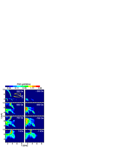
Fig. 1 shows the dependence of the measured power spectral density (PSD) on . The spectra at Oe exhibit three harmonically related peaks at mA, caused by the clamshell precession. The expected fundamental frequency of the OP mode is close to the frequency of the clamshell’s second harmonic near the crossover, since its trajectory is half that of clamshell. The Oe data in Fig. 1 exhibit a spectral feature at mA consistent with this relationship between the two modes. Below, we present measurements and micromagnetic simulations that confirm our interpretation and elucidate other, more complex dynamical behaviors.
At Oe, the OP peak rapidly shifts to higher frequency. Simultaneously, the high-current part of the peak splits from the lower part, and eventually merges with the clamshell peaks ( Oe and Oe data in Fig. 1). One can estimate the precession amplitude based on the total microwave power under the peaks divided by (see also the description of simulations). The largest possible emitted power for hypothetical oscillations between the parallel (P) and antiparallel (AP) configurations of the magnetic layers is pW/mA2 for our sample. The power generated by clamshell precession at Oe, mA is pW/mA2, and by the OP mode at the same and mA is pW/mA2. Both values correspond to the in-plane precession angle exceeding , providing a strong evidence for our interpretation of the spectral peaks as large-angle precessional modes. If these spectral features were induced by inhomogeneous dynamics rather than precession, they would result in significantly smaller microwave power emission. The first clamshell harmonic exhibits the smallest FWHM of MHz at Oe, mA. The peaks decrease in amplitude and broaden with increasing . These behaviors suggest increasingly inhomogeneous dynamics, resulting in decoherence of precession. In contrast, the intensity of the OP peak at mA increases from pW/MHz at Oe to pW/MHz at kOe, while the FWHM remains approximately constant at MHz.
The spectra are asymmetric with respect to the direction of , as illustrated by the difference between the left and the right panels in Fig. 1. The clamshell peaks are consistently broader at than at . At large , they are replaced by incoherent noise rather than the OP mode. The direction of for which the OP mode was observed varied among the samples, indicating extrinsic origin of asymmetry. At large , the data became similar for positive and negative . In particular, the kOe data exhibit a sharp OP peak at mA.
To gain insight into the origin of the behaviors shown in Fig. 1, as a well as other results discussed below, we performed micromagnetic simulations with OOMMF open code software oommf . The simulations included the current-induced ST and Oersted field effects, but neglected thermal fluctuations. The dipolar field was accounted for by subtracting Oe from the in-plane component of . The cell size was nm3. Reducing the size to nm3 did not significantly affect the results. The parameter values available mostly from MR measurements bassreview were used: current polarization , Py exchange stiffness erg/cm, Gilbert damping , and the ratio of the ST magnitudes near the AP and the P states. Saturation magnetization emu/cm3 of Py was determined by magnetometry of a Py(5) film prepared under the same conditions as the nanopillar.
The spectra were calculated from the simulated time-dependent magnetization distribution of the nanopillar. The calculated time-dependent resistance was , where , and . Here, are the local normalized magnetizations of F1 and F2, and denotes averaging over the simulation grid. The ac voltage on the input of the amplifier was obtained by assuming that a constant current is distributed between a load and the sample resistance . Fast Fourier transform (FFT) of over a period of ns with a ps step was performed after relaxation for ns. The power spectral density was determined by , where , and a factor of 2 accounts for the negative- contribution to the FFT.
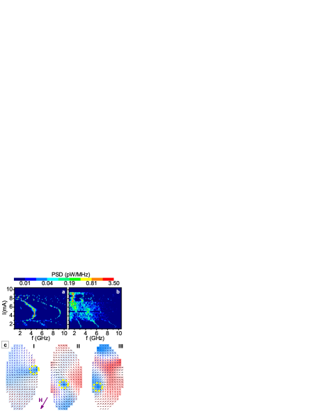
Our calculations showed that a significant asymmetry of spectra with respect to the direction of can be induced by the simultaneous effects of the current-induced Oersted field and a modest asymmetry of the sample geometry. Fig. 2 shows results for a nanopillar approximated by two semi-ellipses with minor semi-axes of nm and nm, and a major axis of nm. Coherent OP precession was obtained at , but was suppressed at by vortices and finite-wavelength spin-waves leedieny . The vortices usually nucleated at the right upper edge of the nanopillar, and annihilated at the lower left edge (Fig. 2c). The chirality of the vortices coincided with the direction of the Oersted field’s rotation, indicating that the asymmetry of spectra is caused by the suppression or enhancement of vortex nucleation due to the interplay of sample shape asymmetry and the effect of Oersted field.
Simulations could not reproduce several features of the data for any reasonable variations of nanopillar shape, distribution of current and its polarization, or Py stiffness. Firstly, the simulated OP peak did not exhibit the rapid shift and splitting with increasing seen in data. Secondly, despite a significant asymmetry of the calculated spectra, they did not reproduce the region at mA where sharp OP peak was present for Oe, but no dynamical features appeared at Oe. The simulations also indicated that the OP mode should exhibit multiple spectral harmonics, while only one or two harmonics could be seen in data, regardless of the large amplitude of precession established from the analysis of peak intensity. These features may be caused by additional effects of spin-polarized current neglected by the model, or by the dynamical states not described by micromagnetic simulations.
The differences between data and simulations also open the possibility that the high-current spectral feature in Fig. 1 is caused by dynamics different from the OP mode. Current-induced excitation of the polarizing layer F2 can lead to microwave peaks, appearing above the onset current determined by the ratio of the volumes of F2 and F1 largecurrent . However, the effective volume of the extended layer F2 in our samples far exceeds that of F1, and thus cannot explain the onset current that at Oe is only times larger than the onset of the clamshell precession. The nanopillar shape imperfections can also result in precession around a configuration intermediate between the AP and P states. However, this intermediate state would quickly become unstable at increased , contrary to the high-field data in Fig. 1. Such a state would also likely appear as an intermediate-resistance step not seen in our dc measurements of MR.

Both measurements and simulations showed that the OP precession is extremely sensitive to the orientation of , when the latter was rotated in the film plane or tilted out of plane. Rotating in the plane changed the dependence of the OP mode frequency on , Fig. 3(a). At , the peak exhibited a blue shift up to mA, above which it gradually red shifted. At smaller values of , the peak broadened, decreased in intensity, and red shifted. The correlation between the width of the OP peak and the dependence of its frequency on is consistent with published simulations cornellnature ; berkovgorn . Namely, blue shift is always predicted in the macrospin approximation, which is more applicable to narrow coherent peaks. In contrast, the peaks can red shift in micromagnetic simulations of the more inhomogeneous dynamics associated with broader spectral peaks. The red shift originates from the decrease of the total magnetic moment of the nanopillar caused by the inhomogeneity. This interpretation was supported by our simulations (Fig. 3(b)), where decreasing resulted in increasingly inhomogeneous OP dynamics. The OP mode red shifted with at small . At larger , it blue shifted at small and red shifted at large , in excellent overall agreement with the data. A somewhat larger was used in simulations to destabilize the static current-induced AP state at large (see discussion of Fig. 1).
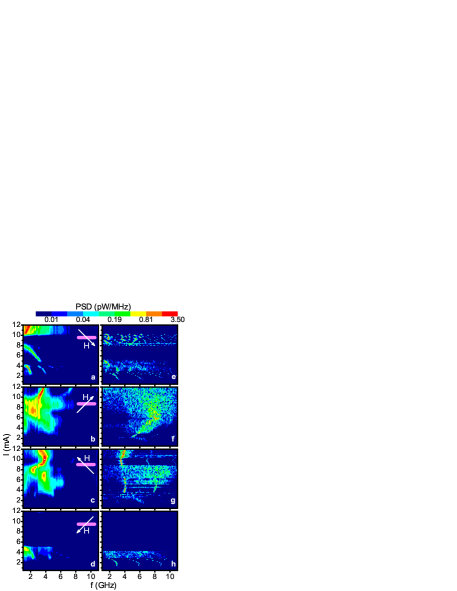
For tilted with respect to the sample plane, the dynamics showed dependence not only on the sign of , but also on its tilting direction (Fig. 4). The component of perpendicular to the film plane was significantly smaller than the demagnetizing field of kOe, resulting in only tilting of when it was static. The OP mode appeared for both directions of above the film plane, and was suppressed for below the film plane. The different response of dynamics to the opposite directions of tilting indicates a significant asymmetry of this state with respect to the film plane. This asymmetry characteristic of the OP dynamics was reproduced by the simulations, as shown in panels (e)-(h). Simulations for tilted above the sample plane showed predominantly coherent OP precession below the plane, in excellent agreement with robust spectral features seen at large in the data of Figs. 4(b,c). We note that simulations with in-plane also showed OP precession below the plane, determined by the relative orientations of and the nanopillar easy axis. In contrast, simulations with tilted below the sample plane showed OP precession above the sample plane suppressed by dynamical inhomogeneities. These results are consistent with the data.
In summary, coherent current-induced dynamics in magnetic nanopillars was achieved by employing an extended polarizing layer. A high-current spectral peak was identified as the out-of-plane precession, whose dependence on the orientation of was in excellent agreement with micromagnetic simulations. The dynamics exhibited a significant asymmetry with respect to the direction of , attributed to a combination of nanopillar shape asymmetry and Oersted field.
This work was supported by the NSF Grant DMR-0747609 and a Cottrell Scholar award from the Research Corporation.
References
- (1) J. Slonczewski, J. Magn. Magn. Mater. 159, L1 (1996).
- (2) S.I. Kiselev, J.C. Sankey, I.N. Krivorotov, N.C. Emley, R.J. Schoelkopf, R.A. Buhrman, D.C. Ralph, Nature 425, 380 (2003).
- (3) I.N. Krivorotov, D.V. Berkov, N.L. Gorn, N.C. Emley, J.C. Sankey, D.C. Ralph, and R.A. Buhrman, Phys. Rev. B 72, 064430 (2007).
- (4) D.V. Berkov, J. Miltat, J. Magn. Magn. Mater. 320, 1238 (2008).
- (5) Z. Li, and S. Zhang, JournalPhys. Rev.B 680244042003.
- (6) D.V. Berkov and N.L. Gorn, Phys. Rev. B 72, 094401 (2005).
- (7) S. Urazhdin, arXiv:0802.1560v1 (2008).
- (8) O. Ozatay, P.G. Gowtham, K.W. Tan, J.C. Read, K.A. Mkhoyan, M.G. Thomas, G.D. Fuchs, P.M. Braganca, E.M. Ryan, K.V. Thadani, J. Silcox , D.C. Ralph , and R.A. Buhrman, Nature Mat. 7, 567 (2008).
- (9) M.J. Donahue and D.G. Porter, OOMMF User’s Guide, NISTIR 6376, NIST Gaithersburg, MD (1999).
- (10) J. Bass and W.P. Pratt Jr., J. Phys.: Condens. Matter 19, 183201 (2007).
- (11) K.J. Lee, A. Deac, O. Redon, J.P. Noziers, and B. Dieny, Nature Mat. 3, 877 (2004).