Bitwist 3-manifolds
Abstract.
Our earlier twisted-face-pairing construction showed how to modify an arbitrary orientation-reversing face-pairing on a faceted 3-ball in a mechanical way so that the quotient is automatically a closed, orientable -manifold. The modifications were, in fact, parametrized by a finite set of positive integers, arbitrarily chosen, one integer for each edge class of the original face-pairing. This allowed us to find very simple face-pairing descriptions of many, though presumably not all, 3-manifolds.
Here we show how to modify the construction to allow negative parameters, as well as positive parameters, in the twisted-face-pairing construction. We call the modified construction the bitwist construction. We prove that all closed connected orientable 3-manifolds are bitwist manifolds. As with the twist construction, we analyze and describe the Heegaard splitting naturally associated with a bitwist description of a manifold.
Key words and phrases:
3-manifold constructions, surgeries on 3-manifolds, Thurston’s geometries1991 Mathematics Subject Classification:
57Mxx1. Introduction
In a series ([1, 2, 3]) of papers, we described and analyzed a simple construction of 3-manifolds from face-pairings. If is an orientation-reversing edge-pairing on a polygonal disk , then the quotient space is always a surface. But if is an orientation-reversing face-pairing on a faceted 3-ball , the quotient is not generally a 3-manifold. (See, for example, Section 2.7 of [4].) For the twist construction one chooses a positive integer, called the multiplier, for each edge cycle (equivalence class of an edge under the action of ). By subdividing each edge into the product of its multiplier and the size of its edge cycle and then precomposing with a twist, one obtains a new faceted 3-ball and orientation-reversing face pairing . The fundamental result of the constuction is that is always a 3-manifold. Papers [1] and [2] give the basic details of the construction. The construction is analyzed further in [3], and Heegaard diagrams and surgery diagrams are given for twisted face-pairing manifolds.
In this paper we give a modified construction which we call the bitwist construction. The basic setup is the same, but we allow the edge cycle multipliers to be positive or negative. Allowing twisting in different directions leads to problems in defining the new face-pairing , but one can resolve this by the appropriate insertion of “stickers” in the faces of the new faceted 3-ball . In Section 2 we give a simple preliminary example to show how stickers are used in the construction. Following this, we give the general construction in Section 3. As with the twist construction, the 3-manifolds constructed from the bitwist construction naturally have a cell structure with a single vertex. One can easily give presentations for fundamental groups of bitwist manifolds as in [2, Section 4], but the homology results of [2, Secton 6] do not generally hold for bitwist manifolds. Since has a single vertex, some of the results from the twist construction apply directly to the bitwist construction. In particular, the construction of Heegaard diagrams and framed surgery descriptions from [3] are valid for the bitwist construction. This is developed in Section 4. If is a corridor complex link for an orientation-reversing face pairing on a faceted 3-ball and mul is a multiplier function for , then the bitwist manifold is obtained by framed surgery on , where the face components have framing and an edge component has framing the sum of its blackboard framing and the reciprocal of the multiplier of its edge cycle.
After making the leap to negative multipliers, it is natural to inquire about multipliers with value 0. Allowing edge cycle multipliers to be 0 amounts to collapsing every edge with multiplier 0 to a point and applying the construction to the resulting complex. In terms of our surgery description, this amounts to deleting from our framed link every component with framing , an operation which does not change the resulting manifold. Collapsing edges in general leads to complexes which are no longer 3-balls – they are cactoids. While we actually do find face-pairings on cactoids interesting and we do temporarily allow multipliers to be 0 in the proof of Theorem 5.5.1, for the present we content ourselves with nonzero multipliers.
The framed surgery descriptions are a primary motivation for developing the bitwist construction. In order to realize 3-manifolds as twisted face-pairing manifolds or bitwist manifolds, one wants to be able to change the framings of the edge components. Suppose is a corridor complex link for a twisted face-pairing manifold. We still get a twisted face-pairing manifold if we replace the framing of each edge component by its blackboard framing plus an arbitrary positive rational number. In Section 5 we show that using the bitwist construction, we still get a bitwist manifold if we replace the framing of each edge component by its blackboard framing plus an arbitrary rational number. This ability to change the signs of the rational numbers gives extra power to the construction. Using this, we show in Section 6 that every closed connected orientable 3-manifold is a bitwist manifold.
2. A preliminary example
We give a preliminary example to indicate the construction. We start with a simple model face-pairing that was considered in Section 2 of [1]. Our faceted 3-ball is a tetrahedron with vertices , , , and , as shown in Figure 1. We consider as an oriented 3-ball, and for convenience give it an orientation so that in the induced orientation on the boundary of the boundary of each 2-cell is oriented clockwise.
The model face pairing identifies the triangles and by reflection in the common edge , and it identifies and by reflection in the common edge . In the permutation notation of [1], is given as follows:

There are three edge cycles, as follows:
The first edge cycle has length , the second edge cycle has length , and the third edge cycle has length . In the twisted face-pairing construction, for each edge cycle one chooses a positive integer called the multiplier. For the bitwist construction, one chooses a nonzero integer , still called the multiplier, for each edge cycle. We use the cycle lengths and the absolute values of the multipliers to determine how to subdivide the edges of . The sign of the multiplier indicates the direction in which we twist edges in the edge cycle . If all of the multipliers have the same sign, then we have the twist construction. For this example, we choose , , and .
We are now ready to replace by its subdivision . We subdivide every edge of into subedges. We perform these subdivisions so that the face-pairing takes subedges to subedges. Let be the resulting faceted -ball. We need to perform a further modification if the multipliers do not all have the same sign. Let be a face of . Suppose is a vertex of in . Let be the edge of in with terminal vertex and let be the edge of in with initial vertex . If and , then we add a sticker (think straight pin with spherical head) to at . That is, we add a new vertex in the interior of and join it to by an edge in . The faceted 3-ball obtained from by adding stickers to as described above is the subdivision . Figure 2 shows the subdivisions and for this example.

We define a bitwisted face-pairing on as follows:
The underlying idea is that we precompose with a twist in the positive direction on an edge which is a subedge of an original edge with positive multiplier, and we precompose with a twist in the negative direction on an edge which is a subedge of an original edge with negative multiplier. This is not well defined on since adjacent original edges can have multipliers of different signs, but one can make it well defined on .
Let , where is the equivalence relation on generated by the face-pairing . The computation below shows that has two 1-cells and a single 0-cell.
Since has two 2-cells and a single 3-cell, and so is a 3-manifold. Figure 3 shows the link of the vertex of . As for the twist construction, can also be obtained as the quotient under the face pairings of a dual faceted 3-ball , and the boundary of is cellularly isomorphic to the dual of the link shown in Figure 3. The subdivision of is shown in Figure 4. It is easy to see from Figure 4 or from the display above that


3. The bitwist construction
We now give the main construction. In [2] we defined a faceted 3-ball to be a regular CW complex. Here we follow the more general definition of a faceted 3-ball given in [3]. In particular, we do not assume that the 2-cells in are regular. As in [3], a faceted 3-ball is an oriented CW complex such that is a closed 3-ball, there is a single 3-cell and its interior is , and does not consist solely of a 0-cell and a 2-cell. It follows from this that for each 2-cell of , there is a CW structure on a closed disk such that i) has a single 2-cell and its interior is and ii) there is a continuous cellular map whose restriction to each open cell is a homeomorphism.
Still following [3], given a faceted 3-ball we construct a subdivision of by barycentrically subdividing . The faceted 3-ball is a regular CW complex and each 2-cell of is a triangle. Since the 2-cells of may not be regular, a face pairing on is technically a matching of the faces of together with a face pairing on which is compatible with it. We still denote by the face pairing on . We assume as before that our face-pairings reverse orientation and satisfy the face-pairing compatibility condition.
Suppose is a faceted 3-ball and is a face-pairing on . We refer to as a model face-pairing. There is an equivalence relation defined on the edges of that is generated by the relation if is the image of under some element of ; the equivalence classes are called edge cycles. If is an edge cycle, we denote its cardinality by and call it the length of . In addition to , the input for the bitwist construction consists of a multiplier function. The multiplier function is a function . An edge is positive if and is negative if .
Suppose we are given a face-pairing together with a multiplier function mul. We create a subdivision of in two stages. The first stage consists of subdividing each edge of into subedges to get a subdivision of , and forming the subdivision of by barycentrically subdividing . We perform these subdivisions so that defines a face-pairing on . The second stage of our construction of consists of adding stickers at some of the corners of the faces of . Suppose is a face of , and consider a corner of at a vertex with edges and , labeled such that precedes . Suppose that is a negative edge and is a positive edge. Let be the edge of which bisects this corner. To we add a barycenter of and the subedge of joining and . This subedge of is a sticker. We continue with this process for all of the corners of all of the faces of . The result is a faceted 3-ball which is obtained from by subdividing edges and adding stickers.
As for and , we form the subdivision from by barycentrically subdividing . We do this so that is a subdivision of . If is a face of , we will still use the name for the corresponding face in ; to cut down on the confusion, we will refer to edges of in as original edges and to vertices of in as original vertices. Note that can be obtained from by splitting certain edges which connect original vertices to barycenters of faces and then for each split edge inserting a digon decomposed into four triangles. See Figure 5, where the edge of joining and is a sticker. In particular, there is a correspondence between faces of and faces of that do not contain subedges of stickers.

We next define a bitwisted face-pairing on . The orientation on , and hence on and , determines a cyclic order on the boundary of each face of and hence a cyclic order on the faces of the subdivision .
Let be a face of , and let be an edge of which is part of an original edge of . See Figure 6, which shows part of and for some face of with positive original edge . The vertices and edges of and are drawn thick for emphasis. Let be a face of the subdivision which contains . If is a positive edge, let be the face of which is the second face before the face of . If is a negative edge, let be the face of which is the second face after the face of . Figure 7 shows and for certain faces and of for the case in which has a sticker. The faces and both contain an original vertex which is contained in the sticker. Note that in from to in the positive direction there are four faces corresponding to the four faces of which contain a subedge of the sticker. It follows that the definition of can be extended to a face-pairing between and . Doing this for each face defines a face-pairing on . Unless the sign of mul is constant, this will not define a face-pairing on . In effect we are using the sign of mul to determine which direction to twist each face of ; the stickers enable us to make this well defined.

We denote by the quotient space of under the equivalence relation generated by .
Theorem 3.1.
Let be a faceted 3-ball, let be an orientation-reversing face-pairing on and let mul be a multiplier function for . Then is a closed 3-manifold. Furthermore, as a cell complex has just one vertex.
Proof.
The proof of the first assertion is an Euler-characteristic argument analogous to the argument in [1]. To prove that is a closed 3-manifold, it suffices to show that . We do this by determining the number of cells in of every dimension. It is clear that has one 3-cell and that the number of 2-cells is the number of pairs of faces of . So to prove Theorem 3.1, it suffices to prove that has one 0-cell and that the number of 1-cells is the number of pairs of faces of .
Every edge of is either a sticker or a subedge of an original edge. The discussion involving Figure 7 shows that the image under of a sticker contained in a face of consists of two edges of . One of these edges of is a terminal subedge of a positive original edge and one is an initial subedge of a negative original edge. The discussion involving Figure 6 implies that every edge of contained in an original edge is equivalent to an edge of a face of such that either is the terminal subedge of a positive original edge of or is the initial subedge of a negative original edge of . We conclude that every edge of is equivalent to an edge of a face such that either is the terminal subedge of a positive original edge of or is the initial subedge of a negative original edge of . Also, if is a face of with a positive original edge followed immediately by a negative original edge , then the terminal subedge of is equivalent to the initial subedge of by means of a sticker. Moreover every vertex of is equivalent to an original vertex.
Now let be an edge of a face of such that is the terminal subedge of a positive original edge of . Also suppose that the original edge of immediately following is positive. By considering the -orbit of we obtain edges of faces of and original edges with the following properties.
We see that , that is the original edge of immediately following , that is the terminal subedge of relative to , that and are equivalent in an orientation-preserving way, that is the terminal subedge of a positive original edge of and that none of the edges is the terminal subedge of an original edge relative to either face containing it. Corresponding statements hold if is an initial subedge of a negative original edge of .
The previous paragraph implies for every face of that the terminal subedges of positive original edges of and and the initial subedges of negative original edges of and are all equivalent and they are not equivalent to any other such edges of other faces. This and the results of the next-to-last paragraph establish a bijection between the 1-cells of and pairs of faces of . Similarly, the last paragraph implies for every face of that its original vertices are equivalent. This and the results of the next-to-last paragraph imply that has just one 0-cell.
This proves Theorem 3.1.
∎
We denote by the subdivision of obtained by replacing the multiplier function mul by .
Theorem 3.2.
Let be a faceted 3-ball, let be an orientation-reversing face-pairing on , and let mul be a multiplier function for . Then the dual of the link of the vertex of is isomorphic to in an orientation-reversing way.
Proof.
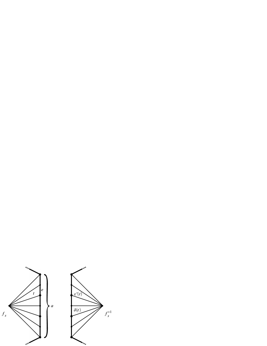
The proof is an adaptation of the arguments for the analogous results in [2] and [3]. Suppose is a face of and is an edge of in . First suppose that is a positive edge. Let be the initial vertex of relative to , let be the terminal vertex of relative to , and let be the edge of preceding in . Let be the vertex of . The image of in has a vertex corresponding to , and this vertex is in a chain of faces; the first face is the image of , the last face is the image of and all of the other faces are digons which are the images of links of vertices of that are not vertices of . Similarly, if is a negative edge, is the terminal vertex of relative to , is the initial vertex of relative to , and is the edge of following in , then the vertex corresponding to in the image of in is in a chain of faces joining the images of and . So in each case, in the dual of there is a segment subdivided into edges which joins the duals of the images of and .
We next need to see how these segments fit together. We suppose for convenience that is a positive edge. Let be the edge of that precedes in and let be the edge of that follows in . If is also a positive edge, then in the dual of there is a face containing a pair of adjacent segments, subdivided into and edges. A similar statement holds if is a positive edge. If is a negative edge, then the edge of preceding in is a sticker, and is the same as the edge of following in . This sticker is the edge of the previous paragraph for both and . So in the dual of the segments corresponding to and are adjacent in some face. If is a negative edge, then the terminal subedge of in and the initial subedge of in are equivalent to a sticker in the face , and so there is a sticker in the dual of between the segments corresponding to and . A similar analysis holds if is a negative edge.
This implies that in the dual of there is a face corresponding to that is cellularly homeomorphic to the face corresponding to in . This correspondence between faces of and faces of the dual of respects adjacency of faces. So the dual of is cellularly homeomorphic to . It follows as in [2] that this homeomorphism reverses orientation.
∎
4. Heegaard diagrams for bitwist manifolds
Let be a bitwist manifold, let be the corresponding subdivision of , and let be the corresponding bitwisted face-pairing on . As in [3, Section 4], one can construct the edge pairing surface of . For each face in , there is a CW structure on a closed disk such that i) has a single 2-cell whose interior is the interior of , ii) there is a continuous cellular map whose restriction to each open cell in a homeomorphism, and iii) there is a continuous cellular map whose restriction to each open cell is a homeomorphism. (And also and are compatible with respect to the face-pairing.) Let be the quotient of the union of the 1-skeleton of and the finite union of the complexes , one for each pair , under the equivalence relation generated by the identifications of with and with for . Then is an orientable closed surface, and the dual cap subdivision of is the edge pairing surface . (See [3, Section 3] for the definition of the dual cap subdivision. The dual cap subdivision of a 2-complex is obtained from its barycentric subdivision by removing the edges joining vertices to barycenters of faces.) Edges of that are contained in or disjoint from are called vertical, and the other edges of are called diagonal. Edges of that are not contained in edges of are called meridian edges, and edges of contained in edges of are called nonmeridian edges.
Theorem 4.1.
Let be a bitwist manifold, and let be the edge pairing surface for the associated bitwisted face pairing. The union of the vertical meridian edges is a basis of meridian curves for , and the union of the diagonal meridian edges is a basis of meridian curves for . Furthermore is a Heegaard diagram for .
Proof.
Since is a manifold with a single vertex, this follows immediately from [3, Theorem 4.2.1].
∎
Figure 8 shows the union of and for the example from Section 2, where is the triangle , is the triangle , and the two sides of the stickers have been identified.

As in [3], the surface can also be decomposed into edge cycle cylinders. The only difference from the construction in [3] is that if is a face of and is either a positive original edge which is preceded by a sticker or a negative original edge that is followed by a sticker, then the sticker is included with that edge in the construction of the edge cycle cylinder. For example, Figure 9 shows, for the example from Section 2, the edge cycle cylinders. Figure 10 shows, for the same example, the edge cycle cylinders with the stickers pushed back to be horizontal edges. Note that, in this view, vertical meridian edges are drawn vertically and diagonal meridian edges are drawn diagonally. This view makes the effect of adding the stickers more apparent. When a diagonal meridian edge crosses a sticker, it changes direction. This reflects the difference in directions of twists corresponding to edge cycles with positive multipliers and edge cycles with negative multipliers.


Let be an edge cycle cylinder, where as in Figure 10 we have pushed the stickers back to be horizontal. Let (resp. ) be a minimal union of vertical (resp. diagonal) meridian edges that joins the two horizontal ends of , chosen so that . Let be a simple closed curve in that separates the ends of , and let , where is the edge cycle associated to . Then is isotopic rel endpoints to , where is a Dehn twist along . Furthermore, as one repeats this construction for the other edge cycle cylinders, the directions of the Dehn twists can all be chosen consistently with respect to an orientation of .
Theorem 4.2.
Let be a bitwist manifold, let be the edge pairing surface for the associated bitwisted face pairing, and let be the vertical meridian curves as in Theorem 4.1. Let be the edge cycles of . For each let be the edge cycle cylinder associated to and let be a Dehn twist along a simple closed curve in which separates the ends of . We choose the ’s so that they twist in consistent directions with respect to a fixed orientation of . Let . Then is a Heegaard diagram for .
Proof.
This follows immediately from Theorem 4.1 and the discussion in the paragraph before the statement of the theorem.
∎
The construction of corridor complex links for bitwist 3-manifolds is the same as their construction in [3, Section 6] for twisted face-pairing manifolds, though the framings change because of the signs of the multipliers. We first recall the construction of corridor complex links.
Suppose is a faceted 3-ball, is an orientation-reversing face-pairing on , and mul is a multiplier function for . Let be the associated bitwist 3-manifold. We form a corridor complex for as follows. We choose a pair and of faces in that are matched by , and choose an edge-path arc in the 1-skeleton of that joins a corner of to its image under in . We then split this edge-path to a thin corridor. This gives a new cell structure on in which the old faces and have been joined by the corridor into a single face. We do this successively for all of the face pairs of , and call the resulting cell structure on the corridor complex .
We next describe a link in in terms of its projection to . For each face of there is an unknotted component of that lies in one of the old faces that are part of that face; we call this component a face component. Next consider one of the old faces that contains a face component. Each edge of that old face corresponds to an edge of the corresponding face in the corridor complex. For each such edge , contains an arc which enters the old face from the barycenter of the edge, crosses under the face component in the old face, crosses over the face component, goes through the corridor, and ends at the barycenter of the edge . These arcs are constructed so that they have no self-crossings or intersections with other such arcs from that face. We construct these arcs for each face of the corridor complex. Suppose is one of the original edges in . If has not been split in the construction of the corridor complex, then at the barycenter of we have the ends of the arcs from the two faces that contain (or from the face that meets with multiplicity two). If has been split in the construction of the corridor complex, then we join the ends of the two corresponding arcs by an arc that goes under the arcs in the corridor. The union of all of these arcs is a finite set of components of that are called edge components. Each edge component crosses exactly those edges of which correspond to an edge cycle of . The corridor complex link is the union of the face components and the edge components. We call a corridor complex link for . A corridor complex link for the example from Section 2 is shown in Figure 11.

Theorem 4.3.
Let be a bitwist 3-manifold, and let be the corresponding corridor complex link. Define a framing on by giving each face component framing and giving the edge component corresponding to an edge cycle the framing plus the blackboard framing of the edge component. Then Dehn surgery on the framed link yields .
Proof.
This follows easily from the proofs of [3, Theorem 6.2.2] and [3, Theorem 6.1.2]. The proof of [3, Theorem 6.2.2] goes through in this greater generality until the last paragraph, when it refers to [3, Theorem 6.1.2]. The statement and proof of [3, Theorem 6.1.2] go through in this greater generality.
∎
5. Generalizing framings of corridor complex links
In this section we develop some of the machinery needed for the proof of Theorem 6.2. We first discuss some well-known techniques for changing framed surgery descriptions of 3-manifolds. We then show that, in a sense made precise in Theorem 5.2.1, connected sums of corridor complex links are corridor complex links. Theorem 5.3.1, that connected sums of bitwist manifolds are bitwist manifolds, follows easily. We next consider a special family of face-pairings called reflection face-pairings, and use them to show that every lens space is a twisted face-pairing 3-manifold. This allows us to prove Theorem 5.6.1, which states that if is a complex corridor link, then for any choices of framings for the edge components we still get a bitwist manifold by framed surgery.
5.1. Dehn surgery preliminaries
We collect some well-known facts about Dehn surgery which will be used later.
We first discuss Rolfsen twists. They appear on page 162 of [5], they appear in Sections 16.4, 16.5 and 19.4 of [7] as Fenn-Rourke moves, and they appear in Section 9.H of [8]. For this let be a link in framed by the elements of . Let be an unknotted component of . Then is contained in a closed solid torus , which is the complement in of a regular neighborhood of . Let be a right hand Dehn twist of . Let . Let be the link gotten from by applying to . We frame as follows. If the -framing of is , then the -framing of is . If is a component of other than with framing , then the image of in has framing , where is the linking number of and after orienting and arbitrarily. When , we say that is obtained from by performing a Rolfsen twist about . In general we obtain by performing Rolfsen twists about . We are interested in Rolfsen twists because the manifold obtained by Dehn surgery on is homeomorphic to the manifold obtained by Dehn surgery on .
We next discuss slam-dunks. These appear on page 163 of [5]. Let be a framed link in . Suppose that one component of is a meridian of another component and that is contained in a topological ball in which meets no components of other than and . Suppose that the framing of is and that the framing of is . Let be the framed link obtained from by deleting and changing the framing of to . We say that is obtained from by performing the slam-dunk which removes . The manifold obtained by Dehn surgery on is homeomorphic to the manifold obtained by Dehn surgery on .
5.2. Connected sums of corridor complex links
Here we establish the fact that the links obtained from the corridor construction are closed under the operation of connected sum in a certain restricted sense.
We begin with two faceted 3-balls and . For let be an orientation-reversing face-pairing on with multiplier function , and let . For let be the link corresponding to as in Theorem 4.3. For , let be an edge component of and let be an edge of which lies in the -edge cycle corresponding to . We assume that either has distinct vertices or has distinct vertices. Let be the faceted 3-ball obtained from by replacing with a digon for . See Figure 12. Because either has distinct vertices or has distinct vertices, we obtain a faceted 3-ball from and by cellularly identifying and . We refer to as a connected sum of and along and . The face-pairings and induce a face-pairing on . Except for choices to be made involving corridors along either or , the corridor constructions for and which give rise to and induce a corridor construction for , which gives rise to an unframed link . The isotopy type of is uniquely determined by , and the identification of and . It is easy to see that is a connected sum of and which joins and . We summarize this paragraph in the following theorem.

Theorem 5.2.1.
Let and be faceted 3-balls with orientation-reversing face-pairings and . Let and be corresponding unframed corridor complex links. Let be an edge component of , and let be an edge component of . Let be an edge of which lies in the -edge cycle corresponding to , and let be an edge of which lies in the -edge cycle corresponding to . Suppose that either has distinct vertices or has distinct vertices. Let be a connected sum of and along and , and let be the corresponding connected sum of and which joins and . Then is an unframed corridor complex link associated to the orientation-reversing face-pairing on induced by and .
Proof.
This is clear from the previous paragraph.
∎
Suppose and are faceted 3-balls. For let be an orientation-reversing face-pairing on and let be a multiplier function for . Let be an edge in and let be an edge in such that . Then the multiplier functions and induce a multiplier function for the face-pairing induced by and on the connected sum of and along and .
5.3. Connected sums of bitwist manifolds
Theorem 5.3.1.
The connected sum of two bitwist manifolds is a bitwist manifold.
Proof.
Let be the faceted 3-ball with just two faces which are degenerate pentagons as in Figure 13. Let be the face-pairing on which fixes the edge common to the two faces, and let mul be the multiplier function for indicated in Figure 13. Figure 14 shows a corridor complex and a corridor complex framed link for and mul.


Now let and be faceted 3-balls with face-pairings and multiplier functions which give rise to bitwist manifolds and . We choose one of the two edges of in the -edge cycle with multiplier , and we form a connected sum of and along this edge and any edge of . Next we choose one of the two edges of in the -edge cycle with multiplier . This edge corresponds to an edge of . We form a connected sum of and along this edge and any edge of . Theorem 5.2.1 easily implies that we obtain a twisted face-pairing manifold which is the connected sum of , , and a manifold which is obtained by Dehn surgery on a framed link which consists of two simply linked unknots with framings 0 and 1. This third connected summand is the 3-sphere. Thus is the connected sum of and .
This proves Theorem 5.3.1.
∎
5.4. Reflection face-pairings
We next consider face-pairings of a very special sort. We assume that our model faceted 3-ball can be identified with the closed unit ball in so that the following holds. The intersection of the unit sphere with the -plane is a union of edges of and the model face-pairing on is given by reflection in the -plane. In other words, we have cell structures on both the northern and southern hemispheres of the unit sphere in , and the face-pairing maps of the model face-pairing are given by the map , which is therefore a cellular automorphism of . In this case we call a reflection faceted 3-ball, and we call a reflection face-pairing. Using the identification of with the closed unit ball in , we speak of the equator of and the northern and southern hemispheres of .
Let be a reflection faceted 3-ball with reflection face-pairing and multiplier function mul. As in Figure 15, we can describe , , and mul using a diagram which consists of a cellular decomposition of a closed disk together with a nonzero integer for every edge. We view this closed disk as the northern hemisphere of . Hence we have the cellular decomposition of the northern hemisphere of , which therefore determines the cellular decomposition of the southern hemisphere of , and the integer attached to the edge is . We sometimes allow ourselves the liberty of attaching 0 to an edge instead of a nonzero integer. Attaching 0 to an edge means that every edge in the corresponding -edge cycle collapses to a vertex.
Let be a reflection faceted 3-ball with reflection face-pairing . Suppose given a multiplier function mul for , and let be the associated bitwist manifold. Theorem 4.3 describes a framed link in the 3-sphere such that Dehn surgery on this framed link gives . In this paragraph we describe another framed link in such that Dehn surgery on also gives . We construct as follows. We identify with the closed unit ball in as in the definition of reflection faceted 3-ball. For every edge of the northern hemisphere of we choose an open topological ball such that is a topological disk which meets and is disjoint from every edge of other than . We assume that such topological balls corresponding to distinct edges are disjoint. For every face of the northern hemisphere of we construct an unknot in the interior of such that if is an edge of , then meets . These unknots are all components of with framings 0. We call these components of face components. Let . Every edge of in the northern hemisphere also gives a component of , called an edge component, as follows. Let be an edge in the equator of contained in the face of the northern hemisphere. The -edge cycle of is just . We define to be a meridian of contained in with framing . Now let be an edge of the northern hemisphere of not contained in the equator. Let and be the faces of which contain . Let be a point of separated by from , and let be a point of separated by from . The -edge cycle of is . We define to be an unknot in with framing such that is a properly embedded arc in joining and . This defines .
Example 5.4.1.


Theorem 5.4.2.
Let be a reflection faceted 3-ball with reflection face-pairing . Suppose given a multiplier function for , and let be the associated bitwist manifold. Let be the framed link in constructed above. Then Dehn surgery on gives .
Proof.
Since is amphicheiral, multiplying all framings by does not change the resulting manifold. So we may assume that . We show how to adapt [3, Theorem 6.1.2] to the present situation.
We construct a handlebody as follows. We still identify with the closed unit ball in . Let be the topological ball which is the closure in of . We construct by attaching handles to as follows. Let and be faces of paired by . Then and are joined by a vertical circular cylinder. We attach such a cylinder to . Doing this for every pair of faces of yields our handlebody . It is clear that the closure in of is also a handlebody. We identify the components of with curves in in a straightforward way.
As in [3, Theorem 6.1.2], let be the edge pairing surface for the bitwisted face-pairing , let be the vertical meridian curves of and let be core curves for the edge cycle cylinders. Then there exists a homeomorphism such that is the face component of corresponding to , this face component being a meridian of , for every . We also have that the edge components of are parallel copies of . The framing determined by of every edge component of is 0. Just as in the proof of Theorem 4.3, the statement and proof of [3, Theorem 6.1.2] go through in this greater generality. So Dehn surgery on gives .
∎
5.5. Lens spaces
In this subsection we show that every lens space is a twisted face-pairing manifold. We will use this in the proof of Theorem 5.6.1.
We begin by defining the notion of a scallop. A scallop is a reflection faceted 3-ball (defined in Section 5.4) whose northern hemisphere has a cell structure essentially as indicated in Figure 17. More precisely, every vertex of a scallop lies on the equator of , contains a vertex such that every edge of not contained in the equator of joins with another vertex, and every vertex of other than is joined with by at least one edge. So the northern hemisphere of a scallop might consist of just a monogon. Otherwise it is subdivided into digons and triangles, in which case it has at least two digons, but it may have arbitrarily many digons.

Theorem 5.5.1.
Let be a scallop with faces in its northern hemisphere. Let be a reflection face-pairing on , let mul be a multiplier function for , and let . Suppose that , , and mul are given by the diagram in Figure 18, where , , and for . (If a multiplier is 0, then the corresponding edge in Figure 18 collapses to a vertex of .) Define integers so that if and if , then , , and for . Then there exist relatively prime positive integers such that is homeomorphic to the lens space , where
(It is possible that , in which case we obtain the 3-sphere.) Furthermore, given relatively prime positive integers and with , then there exists a unique sequence of integers as above such that the above continued fraction equals .

Proof.
Theorem 5.4.2 implies that is given by Dehn surgery on the framed link in Figure 19, where for convenience we have chosen . We repeat that if for some , then the corresponding edge in Figure 18 collapses to a vertex of . In this case the corresponding component of the link in Figure 19 is to be removed. This is consistent with the fact that any component with framing may be removed from a framed link without changing the resulting manifold. We next use Kirby calculus to simplify the framed link in Figure 19. For every we perform the slam-dunk which removes the component with framing . In doing this, the component linked with the given component acquires the framing . We next perform a Rolfsen twist about every component shown in Figure 19 with framing . Every such component is then removed, and 1 is added to the framing of the components linked with it. The resulting framed link is shown in Figure 20. It follows from page 272 of [8] or page 108 of [7] or just by iterating slam-dunks that is the lens space as stated in Theorem 5.5.1.


The uniqueness statement is well known. For this, first note that if , then is an arbitrary positive integer. If , then are arbitrary integers with for . Given and , we calculate by modifying the division algorithm usually used to calculate continued fractions. Instead of taking the greatest integer less than or equal to our given number, we take the least integer greater than or equal to our given number. The details are left to the reader.
This proves Theorem 5.5.1.
∎
Corollary 5.5.2.
Every lens space is a twisted face-pairing manifold.
5.6. Changing the framings
Suppose given an orientation-reversing face pairing on a faceted 3-ball . In Section 4 we construct a corridor complex link by means of link projections. The face components of correspond to the face-pairs of , and the edge components of correspond to the edge cycles of . Given the extra information of a multiplier function mul, we define framings on the components of . We define the framing of each face component to be 0. If is an edge component, then we define the framing of to be the blackboard framing of plus , where is the edge cycle corresponding to . By Theorem 4.3, performing Dehn surgery on with this framing obtains our bitwist manifold . The following theorem states that if we redefine the framing of by replacing each framing of an edge component by an arbitrary rational number, then Dehn surgery on still obtains a bitwist manifold (usually constructed from a different faceted 3-ball).
Theorem 5.6.1.
Let be an unframed corridor complex link. We frame as follows. Let be a component of . If is a face component, then we define the framing of to be 0. If is an edge component, then we define the framing of to be an arbitrary rational number. Then Dehn surgery on with this framing obtains a bitwist manifold.
Proof.
Let be a faceted 3-ball and let be an orientation-reversing face pairing on such that is a corridor complex link for . Let be the edge cycles, and let be the corresponding edge components of . For , let be the blackboard framing of and let such that is the framing on . Let .
Suppose given . If , then we define the multiplier of to be . If , we in effect change the framing of by “attaching a scallop” to our model faceted 3-ball, proceeding as follows.
Suppose that and . Let , and let be positive integers with if such that . As in Theorem 5.5.1, define by if and, if , , , and for . Let be the reflection faceted 3-ball shown in Figure 21, and let be the associated reflection face-paring. Define the multiplier of to be , and define the multiplier function on as indicated in Figure 21.

Now suppose that and . Let , and let be positive integers with if such that . As in Theorem 5.5.1, define by if and, if , , , and for . Let be the reflection faceted 3-ball shown in Figure 22, and let be the associated reflection face-paring. Define the multiplier of to be , and define the multiplier function on as indicated in Figure 22.

We now construct the faceted 3-ball and orientation-reversing face-pairing by repeated connect sums of with the faceted 3-balls for which . For each , we do this via an edge in the edge cycle corresponding to and the edge in which is immediately to the left of the top vertex in Figure 21 or 22. Since the multipliers are compatible on edge cycles that are amalgamated, they define a multiplier function for .
We next construct a framed corridor complex link for . If and , then the link shown in Figure 23 is a framed link for as in Figure 19. This framed link is in fact isotopic to a framed corridor complex link for . If and , then one gets a framed corridor complex link from the link in Figure 23 by multiplying the framing of each component by . By repeated applications of Theorem 5.2.1, one gets a framed corridor complex link for .
Suppose and . Figure 24 shows part of corresponding to . As in the proof of Theorem 5.5.1, we can simplify this to obtain the framed link in Figure 25. Again as in the proof of Theorem 5.5.1, by performing slam-dunks, we may reduce to the framed link in Figure 26. A similar argument holds if and , except that the framing of the meridian component is instead of .


Finally, one performs a slam dunk for each . If , then the framing of becomes
If , then we have . So Dehn surgery on the framed link is a bitwist manifold.
∎
6. Realizing 3-manifolds as bitwist manifolds
In this section we show that every closed connected orientable 3-manifold is a bitwist manifold.
Let be a braid with strands. Following [7], we consider the strands of as joining the points and in , . The closure of is a link in obtained by joining each and by an arc such that the projections of these arcs on the -plane are disjoint from each other and from the projection of onto the -plane. By a generalized closure, we only assume that the endpoints are joined by arcs whose projections are disjoint from each other and from the projection of . This agrees with the definition of closure given in [6], but is more restrictive than that because we are not allowing any more crossings in the projection.
Lemma 6.1.
Every link is a generalized closure of a pure braid.
Proof.
Let be a link in , and let be the projection onto the third coordinate. Then can be isotoped so that, for some integer , the height function on has local maxima, which lie in and local minima, which lie in . Furthermore, we can assume that intersects the -plane in the points , , intersects the plane in the points , , and all crossings of the projection of onto the -plane lie in . (This follows, for example, from Alexander’s theorem, which states that can be represented as the closure of an -strand braid.) For convenience, we call the components of the strands of , we call the components of the tops of , and we call the components of the bottoms of . We first isotope to a link so that there is a strand of joining and and so that there is a top of joining and . This can be done by sliding tops past each other and possibly introducing a crossing in the projection of one top to change the order of its endpoints in the projection. If the strand of descending from ends at , then we repeat this process starting with the strand rising from . Otherwise, by sliding bottoms of past each other and possibly adding a crossing in the projection of one bottom of , we can isotope to a link such that there is a strand of joining and , there is a top of joining and , there is a strand of joining and , and there is a bottom of joining and . One next considers the strand rising from . One can continue this process to isotope to a generalized closure of a pure braid with strands.
∎
We next consider generators for the pure braid group. Let be the pure braid group of isotopy classes of -stranded pure braids. Given , let be the pure braid obtained by doing a full twist on the collection of strands from the to the . Then (if the directions of twisting are chosen properly) is a pure braid for which the strand goes in front of the strands, , and then behind the strands, . Since the elements , , generate the pure braid group, the elements , , generate the pure braid group.
Theorem 6.2.
Every closed connected orientable 3-manifold is a bitwist 3-manifold.
Proof.
Suppose is a closed connected orientable 3-manifold. By the Dehn-Lickorish theorem, can be obtained by Dehn surgery on a framed link . By Theorem 5.3.1 we can assume that is not a split link. By Lemma 6.1, is a generalized closure of a pure braid . We write in terms of the generators . We now view our projection of as lying in the plane . We view the braid as lying in a rectangle , with its strands joining the top and the bottom. The generators of lie in subrectangles which stack together to give the rectangle . Choose such a subrectangle corresponding to a generator of . See Figure 27.a). Then is a full twist on a set of consecutive strands of the braid in . Let be a subrectangle of which contains only the consecutive strands that are twisted in . We next attach a rectangular block to so that the bottom of the block is on . The side of the block facing the top of is the front of the block, and the side of the block facing the bottom of is the back of the block. We replace the strands of that are twisted by parallel strands that go over the front of the block, along the top of the block, and then back down the back of the block. We also drill out a hole in the block that goes through the sides. See Figure 27.b). In effect, we have added a handle to the surface, and have replaced by a trivial braid which goes over the handle. We also choose a circle for the boundary of the block’s hole, and we choose a meridian for the handle. We expand the meridian slightly so that it links the arcs that go over the handle and the circle in the boundary of the hole. See Figure 27.c). We choose framing for the meridian, and framing (depending on the direction of twist of the generator) for the circle in the boundary of the hole. We shrink the block slightly so that blocks corresponding to different subrectangles are disjoint. Doing this for each generator while maintaining the framings of the components of gives a framed link . Let be the surface obtained from the 2-sphere by adding a handle as described above for each generator of .
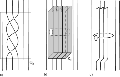
If we perform a slam-dunk on each circle along the boundary of a hole, then the effect on is to delete those circles and to change the framing on each of the meridian circles to . If we now perform a Rolfsen twist along each of the meridian circles, then we recover the original link , but with framings changed by sums and differences of squares of linking numbers of the meridian curves and the components of . Hence if we change the framings on by adding an appropriate integer to each of the components of , we get a framed link such that is obtained from the 3-sphere by surgery on . By Theorem 5.6.1, to prove Theorem 6.2 it suffices to prove that is a corridor complex link whose face components are the meridians.
To get a face pairing, we cut open the surface along the meridians. If there are meridians, the result is a 2-sphere with paired holes and disjoint arcs joining their boundaries. We attach a disk to every hole to obtain a 2-sphere . Since is not a split link, the connected components of the complement in of the union of the arcs and closed disks are all simply connected. The link in Figure 28 gives rise to the surface with curves in Figure 29 (which is taken from [3]). Figure 30 shows the result of cutting open and attaching disks. We fatten each arc to a quadrilateral, foliated by arcs parallel to the core arc, so that adjacent quadrilaterals touch on the boundaries of the disks. See, for example, Figure 31. We now collapse to a point each leaf in a quadrilateral and the closure of each region in the complement of the union of the paired disks and foliated quadrilaterals. By Moore’s theorem the quotient space is a 2-sphere, with a cell structure that consists of a vertex for each collapsed complementary region, an edge for each collapsed foliated quadrilateral, and a face for each of the paired disks. We define a face-pairing on the quotient space in a straightforward way. This defines a face-pairing for a faceted 3-ball whose boundary is the 2-sphere . For the example above, this is shown in Figure 32. By construction, is a corridor complex link for .
∎


References
- [1] J. W. Cannon, W. J. Floyd, and W. R. Parry, Introduction to twisted face-pairings, Math. Res. Lett. 7 (2000), 477–491.
- [2] J. W. Cannon, W. J. Floyd, and W. R. Parry, Twisted face-pairing 3-manifolds, Trans. Amer. Math. Soc. 354 (2002), 2369–2397.
- [3] J. W. Cannon, W. J. Floyd, and W. R. Parry, Heegaard diagrams and surgery descriptions for twisted face-pairing 3-manifolds, Algebr. Geom. Topol. 3 (2003), 234–285 (electronic).
- [4] N. M. Dunfield and W. P. Thurston, Finite covers of random 3-manifolds, Invent. Math. 166 (2006), 457–521.
- [5] R. E. Gompf and A. I. Stipsicz, 4-Manifolds and Kirby Calculus, Graduate Studies in Math., Vol. 20, Amer. Math. Soc., Providence, 1999.
- [6] A. Kawauchi, A Survey of Knot Theory, Birkhäuser Verlag, Basel-Boston-Berlin, 1996.
- [7] V. V. Prasolov and A. B. Sossinsky, Knots, Links, Braids and 3-Manifolds, Amer. Math. Soc., Providence, 1997.
- [8] D. Rolfsen, Knots and Links, Math. Lecture Series 7, Publish or Perish, Wilmington, 1976.