Fair and Efficient TCP Access in the IEEE 802.11 Infrastructure Basic Service Set ***† This work is supported by the Center for Pervasive Communications and Computing, and by National Science Foundation under Grant No. 0434928. Any opinions, findings, and conclusions or recommendations expressed in this material are those of authors and do not necessarily reflect the view of the National Science Foundation.†
Abstract
When the stations in an IEEE 802.11 infrastructure Basic Service Set (BSS) employ Transmission Control Protocol (TCP) in the transport layer, this exacerbates per-flow unfair access which is a direct result of uplink/downlink bandwidth asymmetry in the BSS. We propose a novel and simple analytical model to approximately calculate the per-flow TCP congestion window limit that provides fair and efficient TCP access in a heterogeneous wired-wireless scenario. The proposed analysis is unique in that it considers the effects of varying number of uplink and downlink TCP flows, differing Round Trip Times (RTTs) among TCP connections, and the use of delayed TCP Acknowledgment (ACK) mechanism. Motivated by the findings of this analysis, we design a link layer access control block to be employed only at the Access Point (AP) in order to resolve the unfair access problem. The novel and simple idea of the proposed link layer access control block is employing a congestion control and filtering algorithm on TCP ACK packets of uplink flows, thereby prioritizing the access of TCP data packets of downlink flows at the AP. Via simulations, we show that short- and long-term fair access can be provisioned with the introduction of the proposed link layer access control block to the protocol stack of the AP while improving channel utilization and access delay.
I Introduction
In the IEEE 802.11 Wireless Local Area Networks (WLANs), the Medium Access Control (MAC) layer employs the Distributed Coordination Function (DCF) which is a contention-based channel access scheme [1]. The DCF adopts a Carrier Sense Multiple Access with Collision Avoidance (CSMA/CA) scheme using binary exponential backoff procedure. In DCF, the wireless stations, using all equal contention parameters, have equal opportunity to access the channel. Over a sufficiently long interval, this results in station-based fair access which can also be referred as MAC layer fair access. On the other hand, per-station MAC layer fair access does not simply translate into achieving per-flow transport layer fair access in the commonly deployed infrastructure Basic Service Set (BSS), where an Access Point (AP) serves as a gateway between the wired and wireless domains. Since the AP has the same access priority with the wireless stations, an approximately equal bandwidth that an uplink 802.11 station may get is shared among all downlink traffic. This results in a considerable asymmetry between per-flow uplink and downlink bandwidth.
The network traffic is currently dominated by data traffic mainly using Transmission Control Protocol (TCP) in the transport layer. TCP employs a reliable bi-directional communication scheme. The TCP receiver returns TCP ACK packets to the TCP transmitter in order to confirm the successful reception of the data packets. In the case of multiple uplink and downlink flows in the WLAN, returning TCP ACK packets of upstream TCP data are queued at the AP together with the downstream TCP data packets. When the bandwidth asymmetry in the forward and reverse path builds up the queue in the AP, the dropped packets impair the TCP flow and congestion control mechanisms which assume equal transmission rate both in the forward and the reverse path [2]. As will be described in more detail in Section II-B, unfair bandwidth allocation is observed between not only uplink and downlink TCP flows but also individual uplink TCP flows.
A solution for resolving the unfair access problem in the 802.11 BSS for TCP is limiting the TCP packet source rate for all flows such that no packet drops occur at the AP. This simply translates into limiting the maximum congestion window size of each TCP congestion. In this paper, we propose a simple analytical method to calculate the TCP congestion window limit that prevents packet drops from the AP queue. The proposed analysis shows that this window limit can be approximated by a simple linear function of the bandwidth of the 802.11 WLAN, the number of unlink and downlink flows, the wired link delay of the TCP connection, the MAC buffer size of the AP, and the number of TCP data packets each TCP ACK packet acknowledges. The proposed analysis is generic so that it considers varying number of uplink and downlink TCP flows, the use of delayed TCP ACK algorithm, and varying Round Trip Times (RTTs) among TCP connections. Via simulations, we show that the analytically calculated congestion window setting provides fair access and high channel utilization. As we will also describe, the proposed analysis framework can also be used for buffer sizing at the AP in order to provision fair TCP access.
Motivated by the findings of the proposed analysis and pointing out the potential practical limitations of implementation, we also design a novel link layer access control block to be employed at the AP. The control block manages the limited AP bandwidth intelligently by prioritizing the access of the TCP data packets of downlink flows over the TCP ACK packets of uplink flows. This is achieved by employing a congestion control and filtering algorithm on the TCP ACK packets of uplink flows. The specific algorithm parameters are quantified based on the measured average downlink data transmission rate. We test the performance of the protocol stack enhanced with the proposed access control block in terms of transport layer fairness and throughput via simulations. The simulation results show that fairness and high channel utilization can be maintained in a wide range of scenarios.
The rest of this paper is organized as follows. We illustrate the TCP unfairness problem and provide a brief literature review on the subject in Section II. Section III describes the proposed analytical method to calculate the TCP congestion window limit that prevents packet drops from the AP queue and provides per-flow fair access in the WLAN. Section IV describes the proposed link layer access control block which uses ACK congestion control and filtering for fair access provisioning and evaluates its performance. We provide our concluding remarks in Section V.
II Background
II-A TCP Fairness
The congestion avoidance mechanism adopted in TCP can be characterized by an Additive Increase Multiplicative Decrease (AIMD) algorithm [3]. In the congestion avoidance phase, the congestion window is increased by one at every RTT and is decreased by half (multiplicative decrease) when a packet loss is detected.
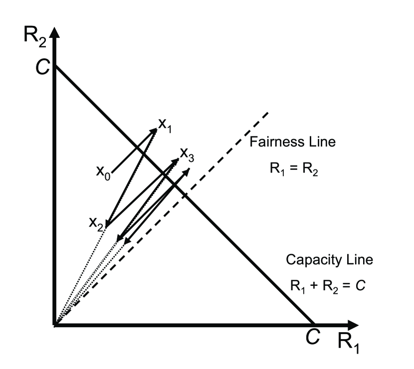
Consider a simple scenario where two flows share a single bottleneck link whose capacity is and they have the same RTT. Assume that both flows are operating in congestion avoidance phase. Let denote the throughput of TCP flowi, .
In Fig. 1, x- and y-axis denote the throughput each flow achieves. Fig. 1 also shows the system capacity limit and the fair throughput lines. Initially, suppose that the values of congestion windows for both flows are such that the throughput pair is achieved as shown by point in Fig. 1. Note that the process described below is independent of where this initial point lies. Since , packet losses rarely occur and both flows increase their congestion windows in an additive increase manner. This increase corresponds to the line in Fig. 1 which connects point to point . As both flows increase their congestion windows in the same rate, the slope of this line is 1/2. At point , since , packet losses occur. On detecting the packet loss, both flows decrease their congestion windows in a multiplicative manner; to point , . This process of alternating increases and decreases continues. But, eventually, the point reaches the fair throughput line and stays always on this line. The fluctuation along this line continues without converging to (0.5C, 0.5C). Therefore, the AIMD algorithm can provide fair bandwidth sharing at the expense of oscillations in the throughput.
The AIMD algorithm can be represented as the following generalized form.
| (1) |
where denotes the congestion window value at the transmission round, , and . For TCP, the additive increase and the multiplicative decrease factors, and in (1), are set to 1 and 0.5, respectively, as described previously. A higher value of increases the convergence rate to the fair throughput. Similarly, a higher value of reduces the oscillations in the throughput after fair share is achieved.
If our assumption that all the flows have the same RTT does not hold, the AIMD algorithm cannot assure fairness. A flow with smaller RTT updates its congestion window quickly and tends to get more bandwidth compared to a flow with larger RTT. Thus, the TCP congestion control shows unfairness among flows with different RTTs.
II-B TCP Unfairness in the 802.11 WLAN
In the 802.11 WLAN, a bandwidth asymmetry exists between contending upload and download flows. This is due to the fact that the MAC layer contention parameters are all equal for the AP and the stations. If stations and an AP are always contending for the access to the wireless channel (saturation222Saturation is the limit reached by the system when each station always has a packet to transmit. Conversely, in nonsaturation, the (nonsaturated) stations experience idle times since they sometimes have no packet to send.), each host ends up having approximately share of the total transmit opportunities over a long time interval. This results in of the transmissions being in the uplink, while only of the transmissions belong to the downlink flows.
This bandwidth asymmetry in the forward and reverse path may build up the AP queue resulting in packet drops. As previously stated, upstream TCP ACKs and downstream TCP data are queued at the AP together. Any TCP data packet that is dropped from the AP buffer is retransmitted by the TCP sender following a timeout or the reception of duplicate ACKs. Conversely, any received TCP ACK can cumulatively acknowledge all the data packets sent before the data packet for which the ACK is intended for, i.e., a consequent TCP ACK can compensate for the loss of the previous TCP ACK. When the packet loss is severe in the AP buffer, the downstream flows will experience frequent timeouts thus congestion window size decreases, resulting in significantly low throughput. On the other hand, due to the cumulative property of the TCP ACK mechanism, upstream flows with large congestion windows will not experience such frequent timeouts. In the latter case, it is a low probability that many consecutive TCP ACK losses occur for the same flow. Conversely, the upstream flows with small congestion windows (fewer packets currently on flight) may also experience timeouts and decrease their congestion windows even more. Therefore, a number of upstream flows may starve in terms of throughput while some other upstream flows enjoy a high throughput. In summary, the uplink/downlink bandwidth asymmetry creates a congestion at the AP buffer which results in unfair TCP access.
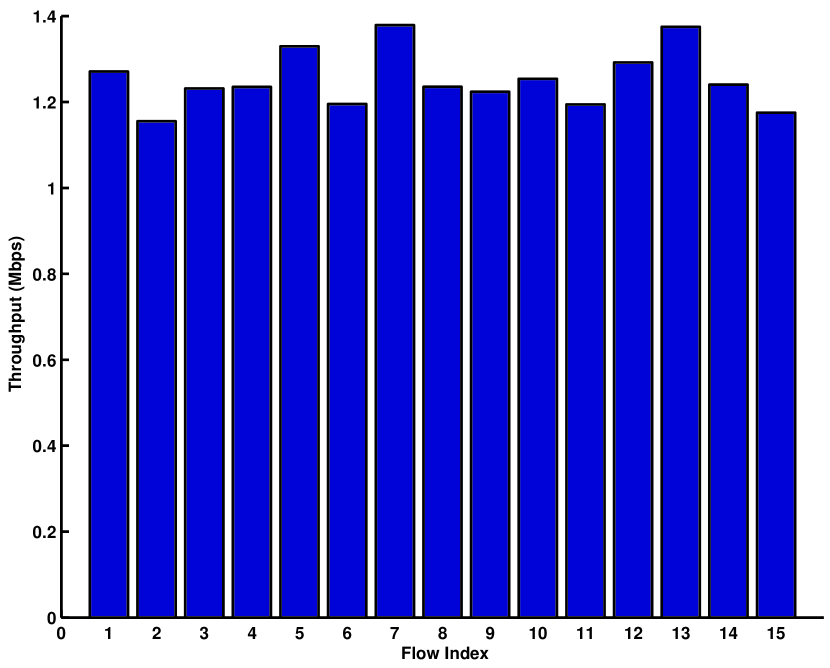
In the first set of experiments, we show that the AIMD congestion avoidance algorithm of TCP leads to fair access when the bandwidth asymmetry problem between the forward and backward links does not exist. We consider a scenario consisting of 15 downlink TCP connections. Each connection is initiated between a separate wireless station and a separate wired station where an AP is the gateway between the WLAN and the wired network. Each station runs a File Transfer Protocol (FTP) session over TCP. Each station uses 802.11g PHY layer with physical layer (PHY) data rate set to 54 Mbps while the wired link data rate is 100 Mbps. The default DCF MAC parameters are used [1]. The AP buffer size is 100 packets. The receiver advertised congestion window limits are set to 42 packets for each flow. Note that the scale on the buffer size and TCP congestion window limit is inherited from [14]. Although the practical limits may be larger, the unfairness problem exists as long as the ratio of the buffer size to the congestion window limit is not arbitrarily large (which is not the case in practice). The packet size is 1500 bytes for all flows.
Fig. 2 shows the average throughput for each downlink TCP connection. The results show that the unfair access problem does not exist if there are no coexisting uplink connections (which limit the forward link bandwidth for downlink connections due to 802.11 uplink/downlink bandwidth asymmetry as described previously). The results illustrate the fair behavior of TCP’s AIMD congestion avoidance algorithm.
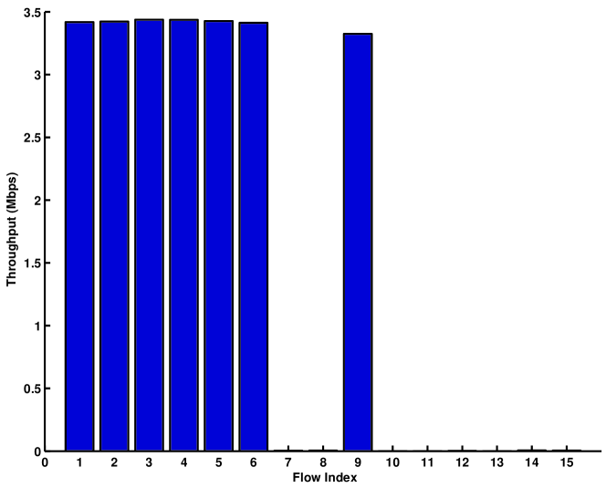
When a similar experiment is repeated for the scenario consisting of only uplink TCP connections, the outcome is very different. Fig. 3 shows the average throughput for each uplink TCP connection a scenario consisting of 15 uplink TCP connections. The results illustrate the unfairness in the throughput achieved by the uplink FTP flows when the backward link bandwidth for TCP ACKs is limited. Eight of the TCP flows starve in terms of throughput as a result of frequent ACK packet losses in the backward link at the AP buffer. As described previously in this section, an ACK packet drop at the AP buffer more likely results in a congestion window decrease when the flow has a small congestion window (i.e., a new connection, or a connection recovering from a recent timeout, etc.). Conversely, a flow with a higher congestion window size may not be affected because of the cumulative ACK feature of TCP.
As the comparison of Fig. 2 and Fig. 3 clearly shows, the cumulative nature of TCP ACKs affects the fair share of the bandwidth significantly, when the bandwidth asymmetry in between the forward and backward links exists.
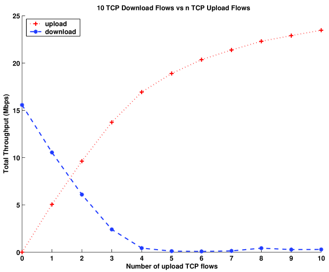
In the second set of experiments, we show the uplink/downlink bandwidth asymmetry for DCF and how this is exacerbated if TCP is employed. We use the same simulation parameters as in the previous experiment. Fig. 4 shows the total TCP throughput in the downlink and the uplink when there are 10 download TCP connections and the number of upload TCP connections is varied from 0 to 10. The unfairness problem between upstream and downstream TCP flows is evident from the results. For example, in the case of 2 upload connections, 10 download TCP connections share a total bandwidth of 6.09 Mbps, while 2 upload TCP connections enjoy a larger total bandwidth of 9.62 Mbps. As the number of upload connections increases, the download TCP connections are almost shut down.
II-C Literature Overview
The studies in the literature on the unfair access problem in the 802.11 WLAN can mainly be classified into two.
The first group mainly proposes access parameter differentiation between the AP and the stations to combat the problem. Distributed algorithms for achieving MAC layer fairness in 802.11 WLANs are proposed in [4], [5]. Several studies propose using the traffic category-based MAC prioritization schemes of IEEE 802.11e standard [6] mainly designed for Quality-of-Service (QoS) provisioning for uplink/downlink direction-based differentiation in order to improve fairness and channel utilization [7, 8, 9, 10, 11]. Algorithms that study enhancements on the backoff procedure for fairness provisioning are proposed in [12, 13]. Although MAC parameter differentiation, adaptation, and backoff procedure enhancements can be effective in fair access provisioning, the 802.11 hardware (Network Interface Cards (NICs), APs, etc.) without these capabilities is still widely deployed. Therefore, in this paper, we focus on techniques that do not require any changes in the 802.11 standard or in the non-AP stations and can directly be implemented via simple software modules in the AP protocol stack.
The second group focuses on designing higher layer solutions such as employing queue management, packet filtering schemes, etc., especially for TCP. The TCP uplink and downlink asymmetry problem in the IEEE 802.11 infrastructure BSS is first studied in [14]. The proposed solution of [14] is to manipulate advertised receiver windows of the TCP packets at the AP. In this paper, we propose a simple analytical model to calculate the congestion window limit of TCP flows for the generic case of delayed TCP ACK schemes and varying RTTs among TCP connections. The results of the proposed analysis can be used in the same way as proposed in [14] for fair and efficient access provisioning. Per-flow queueing [15] and per-direction queueing [16] algorithms where distinct queues access the medium with different probabilities are designed for fair access provisioning. A rate-limiter block which filters data packets both in the uplink and the downlink using instantaneous WLAN bandwidth estimations is proposed in [17]. Differing from all of these techniques, in our previous work, we proposed using congestion control and filtering techniques on top of the MAC queue to solve the TCP uplink unfairness problem [18]. The work presented in this paper proposes a novel congestion control and filtering technique which also considers the TCP downlink traffic. Note that since TCP downlink traffic load is expected to be larger than the uplink traffic load, this enhancement is vital for a practical implementation.
An extensive body of work exists relating to the impact of asymmetric paths on TCP performance [19, 20] in the wired link context. The effects of ACK congestion control on the performance of an asymmetric network are analyzed in [21] for wired scenarios consisting of only one or two simultaneous flows. The effects of forward and backward link bandwidth asymmetry have been analyzed in [22] for a wired scenario consisting only one flow. Similar effects are also observed in practical broadband satellite networks [23]. The effects of delayed acknowledgements and byte counting on TCP performance are studied in [24]. Several schemes are analyzed in [25] for improving the performance of two-way TCP traffic over asymmetric links where the bandwidths in two dimensions differ substantially. The ACK compression phenomenon that occurs due to the dynamics of two-way traffic using the same buffer is presented in [26]. In this paper, we design a novel ACK congestion control and filtering algorithm to be implemented as a link layer access control block in the protocol stack at an 802.11 AP. The congestion control and filtering algorithm is unique in that the parameters of the algorithm are quantified according to the TCP access characteristics in an 802.11 infrastructure BSS.
III TCP Fairness Analysis
The TCP unfairness problem originating from the uplink/downlink access asymmetry can be resolved if packet drops at the AP buffer are prevented such as in the unrealistic case of infinitely long AP queue. In this case, congestion windows of all TCP flows whether in the downlink or uplink reach up to the receiver advertised congestion window limit and stay at this value. This results in fair access in opposed to the fact that the access is asymmetric in the 802.11 infrastructure BSS as described in Section II-B. As the infinitely long queue assumption is unrealistic, the exact same result of no packet drops can be achieved if TCP senders are throttled by limiting the number of packets in flight, i.e., the TCP congestion windows are assigned regarding the available AP bandwidth in the downlink. In this section, we propose a simple and novel analytical model to calculate the maximum congestion window limit of each TCP flow that prevents packet losses at the AP buffer, therefore provides fair and efficient TCP access in the BSS.
Each random access system exhibits cyclic behavior. The cycle time is defined as the average duration in which an arbitrary tagged station successfully transmits one packet on average. Our analytical method for calculating the TCP congestion window limit that achieves fair and efficient access is based on the cycle time analysis previously proposed for 802.11 MAC performance modeling [27],[28]. The simple cycle time analysis assesses the asymptotic performance of the DCF accurately (when each contending AC always has a packet in service). We use the approach in [27] to derive the explicit mathematical expression for the average DCF cycle time when necessary. In Section III-B, we will describe the necessary extensions to employ the cycle time analysis in the proposed analysis. Due to space limititations, the reader is referred to [27],[28] for details on the derivation of cycle time.
We consider a typical network topology where a TCP connection is initiated between a wireless station and a wired station either in the downlink or the uplink of the WLAN. The WLAN traffic is relayed to the wired network through the AP and vice versa. Let Round Trip Time (RTT) denote the average length of the interval from the time a TCP data packet is generated until the corresponding TCP ACK packet arrives. RTT is composed of three main components as follows.
-
•
Wired Link Delay (): The flow-specific average propagation delay of the packet between the AP and the wired node.
-
•
Queueing Delay (): The average delay experienced by a packet at the wireless station buffer until it reaches to the head of the queue. Note that due to the unequal traffic load at the AP and the stations, and may highly differ.
-
•
Wireless Medium Access Delay (): The average access delay experienced by a packet from the time it reaches to the head of the MAC queue until the transmission is completed successfully.
Then, RTT is calculated as follows333RTT is calculated as in (2) irrespective of the direction of the TCP connection. On the other hand, specific values of and depend on the packet size, the number of contending stations, etc. Therefore, RTT of an uplink connection may differ from RTT of a downlink connection..
| (2) |
For the first part of the analysis, each TCP data packet is assumed to be acknowledged by a TCP ACK packet where this assumption is later released and the delayed TCP ACK algorithm is considered.
We claim that if the system is to be stabilized at a point such that no packet drops occur at the AP queue, then the following conditions should hold.
-
•
All the non-AP stations are in nonsaturated condition.
Let’s assume a station has packets (TCP data or ACK) in its queue. A new packet is generated only if the station receives packets (TCP ACK or data) from the AP (as a result of ACK-oriented rate control of TCP). Let users to be active. Every station (including the AP) sends one packet successfully every cycle time [27]. In the stable case, while the tagged station sends packets every cycle time, it receives only one packet. Note that the AP also sends packets during cycle times, but on the average, of these packets are destined to the stations other than the tagged one. Therefore, after cycle times, the tagged stations queue size will drop down to . Since , the tagged stations queue will get empty eventually. A new packet will only be created when the AP sends a TCP packet to the tagged station which will be served before it receives another packet (on average). This proves that all the non-AP stations are in nonsaturated condition if no packet losses occur at the AP.
-
•
The AP contends with at most one station at a time on average.
Following the previous claim, a non-AP station (which is nonsaturated) can have a packet ready for transmission if the AP has previously sent a packet to the station. There may be transient cases where the instantaneous number of active stations may become larger than 1. On the other hand, as we have previously shown, when , the queue at any non-AP station eventually empties. If we assume the transient duration being very short, the number actively contending stations on average is one. Therefore, at each DCF cycle time, the AP and a distinct station will transmit a packet successfully.
We define as the duration of the average cycle time during which the AP sends an arbitrary packet (TCP data or ACK) successfully. We will derive in Section III-B. Let the average duration between two successful packet transmissions of an arbitrary flow at the AP (or at the non-AP station) be . Assuming there are and upload and download TCP connections respectively, we make the following approximation based on our claims that the AP contends with one station on average and the TCP access will be fair if no packet drops are observed at the AP buffer
| (3) |
As it will be shown by comparing with simulation results in Section III-E, the approximation in (3) leads to analytically correct results.
Then, the throughput of each station (whether it is running an uplink or a downlink TCP connection) is limited by (in terms of packets per second). We can also write the TCP throughput using , where we define as the TCP congestion window limit for a TCP connection. Following our previous claims, (the stations are nonsaturated), (we consider the limiting case when the AP buffer is full, but no packet drop is observed), and (the AP contends with one station on average), where is the buffer size of the AP MAC queue. Using , we find
| (4) |
Note that is an indication of the bandwidth at the bottleneck (at the AP). If the data rate exceeds this bandwidth, the excess data will be queued at the AP, eventually overflowing the AP buffer. We calculate considering a full AP buffer, therefore, is the maximum congestion window limit for a TCP connection that prevents the packet drops at the AP queue of size .
We can make following observations from (4).
-
•
is a function of . Therefore, is flow-specific and varies among connections with different .
-
•
The first term is the effective number of packets that are in flight in the wired link for any flow, while the second term is the number of packets that are in the AP buffer for the same flow.
III-A Delayed TCP Acknowledgements
In the delayed TCP ACK mechanism, the TCP receiver acknowledges every TCP data packets (). A typical value (widely used in practice) is .
The use of delayed TCP ACK mechanism changes the system dynamics. On the other hand, we still employ our assumption that the AP contends one station at a time on the average to calculate . As will be shown by comparison with simulation results in Section III-E, this assumption still leads to analytically accurate results.
We update (3) and (4) accordingly for delayed TCP acknowledgments. Let the average duration between two successful packet transmissions of the flow at the non-AP station be when delayed TCP acknowledgment mechanism is used. Each uplink flow completes the successful transmission of packets in an interval of average length . When the access is fair, the AP transmits data packets for each downlink flow (i.e., a total of ), and one ACK packet for each uplink flow (i.e., a total of ACK packets) during the same interval. Then,
| (5) |
| (6) |
III-B Calculating
We are interested in the case when there are two active (saturated) stations (as the AP contends with one station at a time). The average cycle time in this scenario can easily be calculated using the model in [27]. In our case, the AP sends the TCP ACK packets of the uplink TCP connections and the TCP data packets of the downlink TCP connections which contend with the TCP ACK packets of the downlink TCP connections and the TCP data packets of the uplink connections that are generated at the stations. Note that the cycle time varies according to the packet size of contending stations. Then,
| (7) |
where is the set of different types of packets, is the probability that the AP is sending a packet of type , is the probability that the non-AP station is sending a packet of type , and is the average cycle time when one station is using a packet of type and the other is using a packet type of . We differentiate between the data and the ACK packets because the size of the packets thus the cycle time duration depends on the packet type.
Using simple probability theory, we can calculate and as follows
| (8) |
| (9) |
III-C Fair Congestion Window Assignment (FCWA)
A control block located at the AP can modify the advertised receiver window field of the ACK packets that are all relayed through with the value calculated using the proposed model. Therefore, we call this procedure Fair Congestion Window Assignment (FCWA). The analysis requires accurate estimations on and . The control block may distinguish among TCP connections via the IP addresses and the ports they use. An averaging algorithm can be used to calculate the average time that passes between sending a data (ACK) packet into the wired link and receiving the ACK (data) packet which generated by the reception of the former packet (which is ). The TCP header of consecutive ACK packets may be parsed to figure out the value of . It is also worth to note that although the analytical calculation uses a simple cycle time method in calculating and , the AP may use a measurement-based technique rather than the model-based technique used in this paper.
III-D Buffer Sizing
The proposed analysis can also directly be used for buffer sizing purposes. The 802.11 vendors may use the proposed method with statistics of TCP connections and WLAN traffic to decide on a good size of AP buffer that would provide fair TCP access.
| (10) |
III-E Performance Evaluation
We validate the analytical results obtained from the proposed model via comparing them with the simulation results obtained from ns-2 [29]. We obtained via simulations in such a way that increasing the TCP congestion window limit of TCP connections by one results in a packet loss ratio larger than at the AP buffer.
As previously stated, the network topology is such that each wireless station initiates a connection with a wired station and where the traffic is relayed to/from the wired network through the AP. The TCP traffic uses a File Transfer Protocol (FTP) agent which models bulk data transfer. TCP NewReno with its default parameters in ns-2 is used. All the stations have 802.11g PHY [30] with 54 Mbps and 6 Mbps as the data and the basic rate respectively. The wired link data rate is 100 Mbps. The default DCF MAC parameters are used [1]. The packet size is 1500 bytes for all flows. The MAC buffer size at the stations and the AP is set to 100 packets.
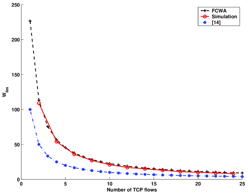
In the first set of experiments, we set the wired link delay of each connection to 50 ms. Each TCP data packet is acknowledged by an ACK packet (). In Fig. 5, we compare the estimation of (4) on the congestion window limit with the values obtained from the simulation results and the proposed method of [14] for increasing number of TCP connections. The number of upload flows is equal to the number of download flows. As Fig. 5 implies, the analytical results for FCWA and the simulation results are well in accordance. The analysis in [14] calculates the congestion window limit by and underestimates the actual fair TCP congestion window limit.
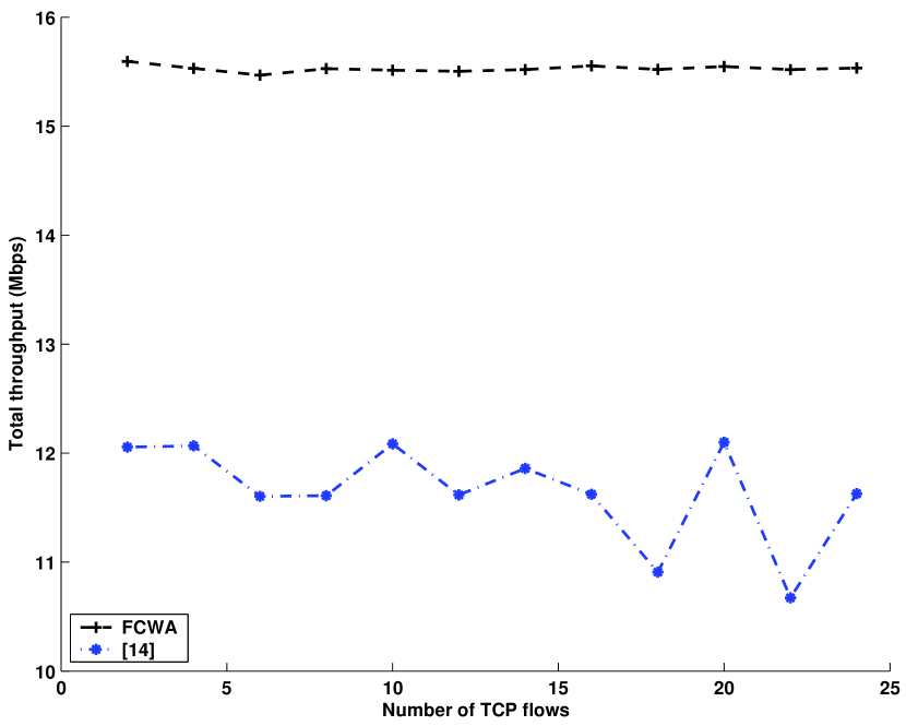
The total throughput of the system when the TCP connections employ analytically calculated congestion window limits in simulation for increasing number of TCP connections is shown in Fig. 6. As the comparison with [14] reveals, the congestion window limits calculated via FCWA result in approximately 35% - 50% higher channel utilization for the specific scenario. Although the corresponding results are not displayed, both methods achieve perfect fairness in terms of per-connection FTP throughput (Jain’s fairness index [31], where 1 shows perfect fairness).
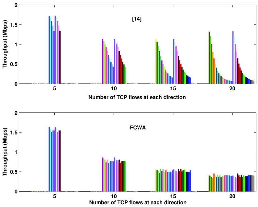
In the second set of experiments, we consider a scenario where wired link delays () among TCP connections differ. First TCP connection has a 1 ms wired link delay, and connection has ms larger wired link delay than connection. Fig. 7 shows the individual throughput for each TCP connection for FCWA and [14] for 4 different scenarios. In Fig. 7, for any scenario, the first half are upload flows and the rest are download flows. As the results present, the congestion window limits calculated by the proposed model maintains fair access even in the case of varying wired link delays. On the other hand, the method proposed in [14] fails to do so.
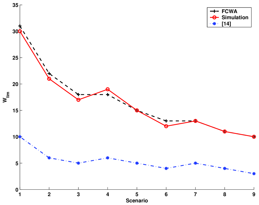
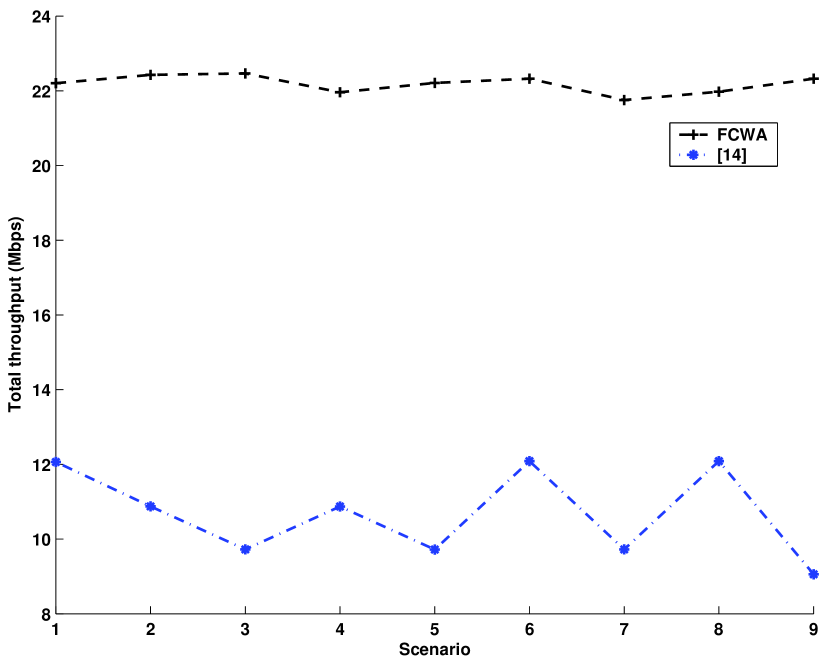
In the third set of experiments, we consider a scenario where the TCP connections use the delayed ACK mechanism with . We consider 9 different scenarios where in each scenario the number of uplink and downlink TCP connections varies. In the first three scenarios, the number of downlink flows is set to 5 and the number of uplink flows is varied among 5, 10, and 15, respectively. Varying the number of uplink flows in the same range, the next three scenarios use 10, and the following three scenarios use 15 downlink flows. In Fig. 8, we compare the estimation of (6) on the congestion window limit with the values obtained from the simulation results and the proposed method of [14]. The analytical results for the proposed model and the simulation results are well in accordance.The total throughput of the system when the TCP connections employ the analytically calculated congestion window limits is shown in Fig. 9. As the comparison with [14] reveals, the congestion window limits calculated via our method result in approximately 90% - 105% higher channel utilization. Although the corresponding results are not presented, the congestion window limits calculated by both the proposed method and the method of [14] achieve perfectly fair resource allocation in terms of throughput (Jain’s fairness index, ). On the other hand, the proposed FCWA method results in a significantly higher channel utilization.
IV Link Layer Access Control Block
As illustrated in Section II-B, unfair access problem originates from the uplink/downlink bandwidth asymmetry in the 802.11 BSS. As our analysis in Section III shows, fair access can be achieved if the congestion window limits of the downlink and the uplink TCP sources are set regarding the network bandwidth so that no packet drops occur at the AP buffer. Actually, for the default DCF scenario when only downlink flows are present, the data packet drops at the AP buffer implicitly throttles the downlink TCP sources effectively (i.e., TCP access is fair among downlink flows in this case as also we present in [32] via simulations). Conversely, the coexistence of uplink flows shuts down the downlink as some uplink flows are fortunate enough to reach a high congestion window by making use of the cumulative property of TCP ACKs. The TCP ACKs of uplink flows occupy most of the AP buffer which results in data packet drops for downlink flows.
These observations motivate the approach of our novel idea: Prioritize TCP data packets of downlink flows over TCP ACK packets of uplink flows at the AP MAC buffer. We design a novel link layer access control block which employs an ACK Congestion Control and Filtering (ACCF) scheme. The proposed ACCF scheme delays the TCP ACK packets of uplink flows (using a separate control block buffer) regarding the measured average packet interarrival time of the downlink TCP data packets. In other words, the downlink data to uplink ACK prioritization ratio is quantified by means of estimating what the uplink ACK transmission rate should be for the given average downlink TCP data transmission rate. The rationale behind the proposed method is sending the TCP ACKs of uplink connections only as often as the TCP data of downlink connections are sent.
The proposed ACCF algorithm uses the cumulative property of TCP ACKs by employing ACK filtering. If another ACK packet of flow is received while there is an ACK packet of flow in the control block buffer, the previous ACK in the buffer is replaced with the new one. Our rationale behind introducing ACK filtering is to reduce the number of ACK packets transmitted by the AP. This creates more room in the AP buffer for TCP data packets of downlink flows (which in turn decreases TCP data packet loss ratio). Moreover, filtering ACK packets also slows the growth rate of TCP congestion windows of uplink flows (since the TCP senders receive less frequent ACK packets) which further limits the share of the uplink bandwidth.
We define the following notation for the description of the algorithm provided in the sequel. Let be the current number of accumulated ACKs for flow in the access control block buffer. Let denote the total time that has passed since the last TCP ACK for flow has been sent to the MAC queue. Let be a constant weighing factor and be a variable weighing factor which is a function of . Let be the measured average packet interarrival time for flow 444 denotes the average TCP data packet interarrival time if flow is a downlink TCP flow and the average TCP ACK packet interarrival time if flow is an uplink TCP flow. can be calculated by employing simple averaging methods (such as exponential moving averaging that we have employed for uplink measurements in [18]) on periodic measurements results.. Let be the average downlink data interarrival duration which we use on deciding how frequent the ACKs of uplink flows should be sent down to the MAC queue for transmission. We calculate by taking the mean of of the downlink flows with where is a constant. Note that this averaging calculation excludes the TCP sources with packet interarrivals higher than a threshold (as quantified by ) in order to prevent slow downlink flows limiting the frequency of uplink ACKs, therefore the uplink bandwidth unnecessarily.
According to the proposed ACCF algorithm, the TCP ACKs are scheduled for transmission (sent down to the MAC queue) such that the average per-flow ACK rate does not exceed the average per-flow TCP downlink packet rate. Using this idea, we quantify the control queue buffering time for each ACK packet of uplink flow as . The rationale behind this equation is as follows.
-
•
We consider the cumulative number of ACK packets that the currently buffered ACK packet represents. The transmission of an accumulated ACK packet is expected to trigger the generation of data packets in the uplink. Therefore, any accumulated TCP ACK packet is delayed until that many TCP downlink data transmissions can be made on average ().
-
•
If a few consecutive timeouts are experienced when the TCP congestion window is small, the uplink TCP flow may hardly recover, and consequently may suffer from low throughput (as we also observed via simulations). Therefore, we introduce an adaptive weighing factor in the minimum buffering duration. We use the value of as an indication of the current size of the TCP congestion window of the corresponding flow. The value of is set smaller than 1 when is smaller than a threshold, . The idea is to prevent longer delays at the control block buffer thus possible timeouts at the TCP agent at the station if the uplink TCP connection is expected to have a small instantaneous congestion window (e.g., a recently initiated TCP connection).
-
•
We substract from in order to make the duration of the interval between two consecutive ACKs sent down to the MAC buffer approximately equal to (in the case ).
As we have also observed via simulations, the ACK filtering scheme makes the ACK arrivals to the AP queue bursty [2]. For an arbitrary uplink flow, this behavior corresponds to alternating idle times with no packet arrivals and active times consisting of a bunch of highly frequent ACK arrivals to the AP queue. This bursty behavior may result in (probably when the corresponding idle duration is long), therefore , especially for the first few ACK arrivals at the AP queue following an idle time for the corresponding flow. Note that the case of actually translates into the case of the ACK being already due for transmission. In this case, our design takes one of the two alternative actions regarding the value of as follows.
-
•
: This serves as an indication of the last ACK pass to the MAC queue having been done probably within the previous burst. Although the ACK transmission is due (), an immediate pass to the MAC queue punishes uplink throughput unnecessarily as (which is an indication of average data transmission interval for uplink flow ) is much larger than . In this case, the ACK packet of flow is delayed for the duration equal to in the control block queue (counting on the high probability of further ACK arrivals in the current burst). Our intuition behind the calculation of is the possibility of the next ACK of the same flow arriving possibly in an average interarrival time . We also introduce the constant weighing factor in order to compensate for the potential variance of the instantaneous ACK interarrival time. A new ACK arrival will probably decrease taking it closer to .
-
•
If , the relaying ACK packet is sent down to the MAC queue as the ACK is already due for transmission and is close to .
As previously stated, if a new TCP ACK packet arrives before the timer that is initially set to (or ) at the arrival of previous ACK expires, the new ACK replaces the previously buffered ACK. The link layer access control block parses the TCP header to calculate and restarts the timer with the new (or ) for the accumulated ACK. When the timer expires, the TCP ACK is sent down to the MAC queue and both and are reset to 0.
ACK filtering may slow down the congestion window growth rate, negatively impact the performance during loss recovery and slow start, and increase the round trip time [21]. On the other hand, since our idea is trying to slow down uplink TCP flows in order to prioritize downlink TCP flows, most of these issues do not negatively affect fairness and overall channel utilization. Still, the proposed algorithm does not filter the TCP ACKs with flags set such as duplicate ACKs which are directly enqueued to the MAC queue.
The proposed ACCF algorithm introduces a number of configurable variables. As pointed out in Section IV-B, we decided the values for these variables through extensive simulations.
IV-A Fairness Measure
Most of the studies in the literature quantify the fairness by employing Jain’s fairness index [31] or providing the ratio of the throughput achieved by individual or all flows in the specific directions. On the other hand, such measures have the implicit assumption of each flow or station demanding asymptotically high bandwidth (i.e., in saturation and having always a packet ready for transmission). As these measures quantify, a perfectly fair access translates into each flow or station receiving an equal bandwidth. On the other hand, in a practical scenario of flows with finite and different bandwidth requirements (i.e., some stations in nonsaturation and experiencing frequent idle times with no packets to transmit), these measures cannot directly be used to quantify the fairness of the system.
We define the fair access in a scenario where flows with different bandwidth requirements coexist as follows.
-
•
The flows with total bandwidth requirement lower than the fair per-flow channel capacity in the specific direction receive the necessary bandwidth.
-
•
The flows with total bandwidth requirement higher than the fair per-flow channel capacity receive an equal bandwidth.
In order to quantify fair access, we propose to use the MAC queue packet loss rate (a packet loss rate of 0 for all flows corresponds to fair access) for the latter together with the comparison on channel access rate (equal channel access rate corresponds to fair access) for the former. Note that the latter can employ Jain’s fairness index, , which is defined in [31] as follows: if there are concurrent connections in the network and the throughput achieved by connection is equal to , , then
| (11) |
IV-B Performance Evaluation
We implemented the proposed link layer control access block employing ACCF in ns-2 [29]. The network topology and the stated parameters in III-E are used. The TCP traffic uses either a File Transfer Protocol (FTP) agent, which models bulk data transfer or a Telnel agent, which simulates the behavior of a user with a terminal emulator or web browser. Unless otherwise stated, flows are considered to be lasting through the simulation duration and called long-lived in the sequel. On the other hand, in some experiments, we also use short-lived TCP flows which consist of 31 packets and leave the system after all the data is transferred. The receiver advertised congestion window limits are set to 42 packets for each flow. Note that the scale on the buffer size and TCP congestion window limit is inherited from [14]. Although the practical limits may be larger, the unfairness problem exists as long as the ratio of the buffer size to the congestion window limit is not arbitrarily large (which is not the case in practice). We found , , , and to be appropriate through extensive simulations. The simulation duration is 350 ms.
We investigate the system performance when wired link delays () differ among TCP connections. The wired link delay of the first upload or download TCP connection is always set to 10 ms. Then, any newly generated upload or download TCP connection has a wired link delay of 2 ms larger than the previous one in the same direction.
The Basic Scenario
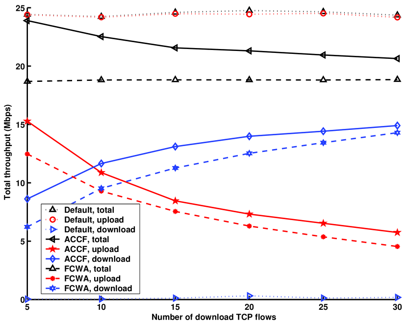
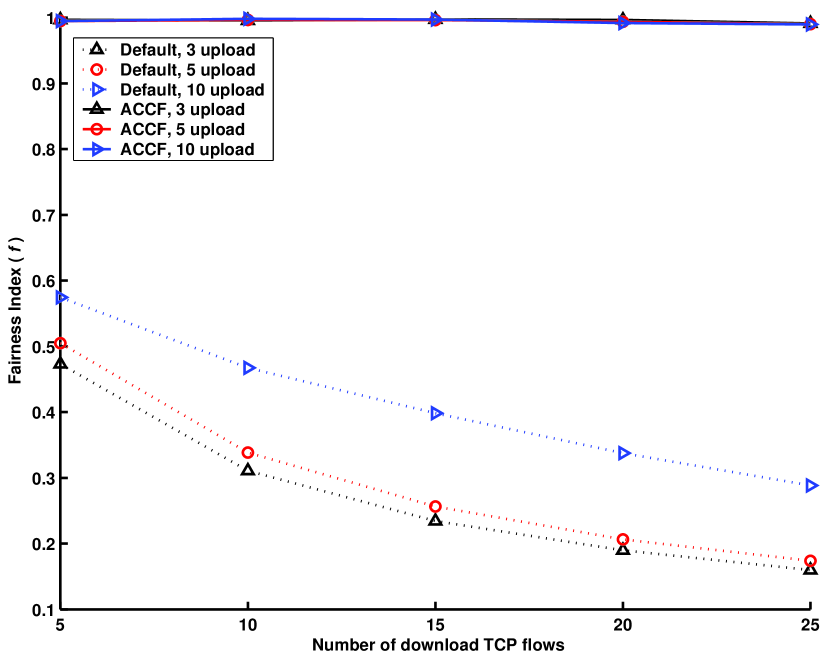
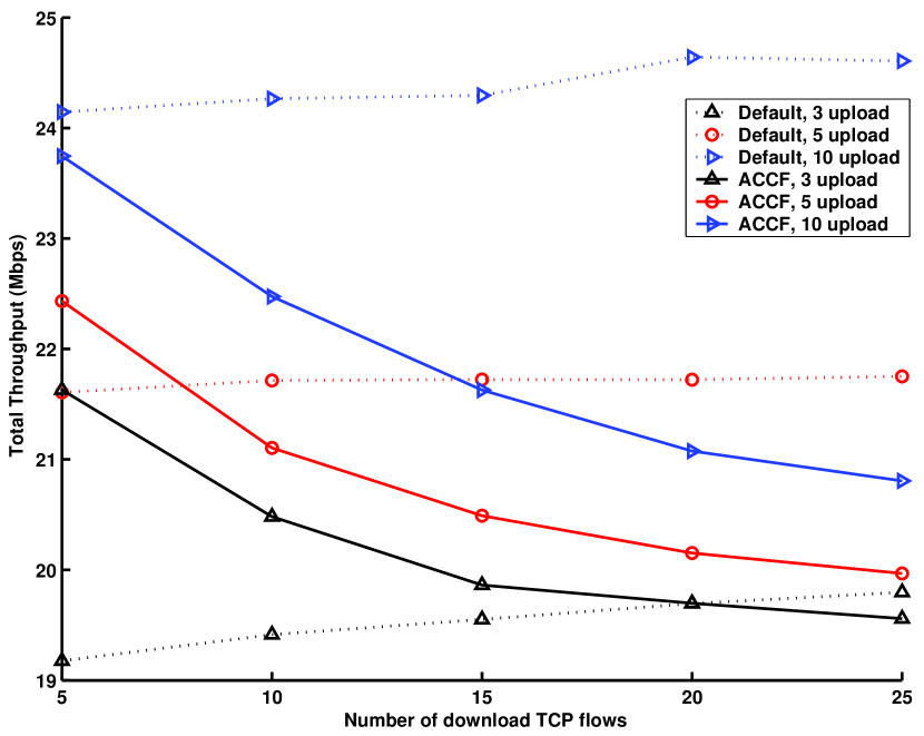
In the first set of experiments, we generate 3, 5, or 10 upload FTP connections and vary the number of download FTP connections from 5 to 30. The wireless channel is assumed to be errorless.
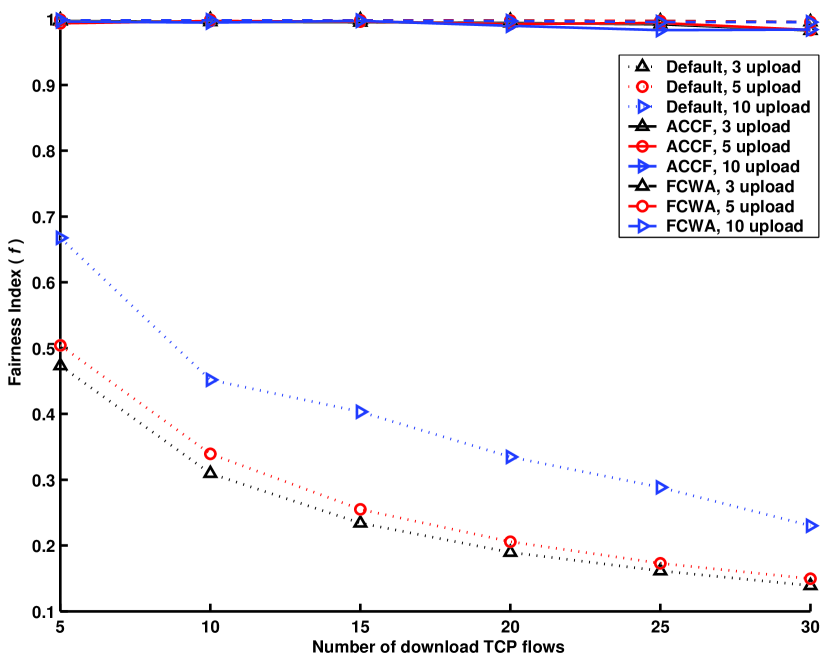
Fig. 10 shows the fairness index among all connections. We compare the default DCF results with the results obtained when the AP employs the proposed i) FCWA or ii) ACCF. As the results imply, with the introduction of any of the proposed control blocks at the AP, an almost perfect fair resource allocation can be achieved in both cases.
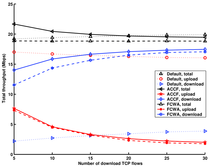
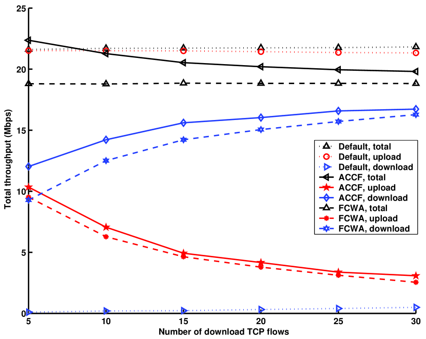
In Fig. 11, Fig. 12, and Fig. 13, we plot the uplink, the downlink, and the total TCP throughput in the infrastructure BSS, when there are 3, 5, and 10 upload TCP connections, respectively. As the results show, using the proposed ACCF scheme, the downlink flows (which starve in the default DCF case) can achieve reasonable throughput. If we employ FCWA instead, the total throughput observed is slightly lower. In this case, the proposed ACCF scheme makes use of the ACK filtering scheme to achieve a higher channel utilization. The comparison with the performance of the default DCF algorithm implies that the proposed methods do not sacrifice channel utilization while providing fair access.
Delayed TCP ACKs
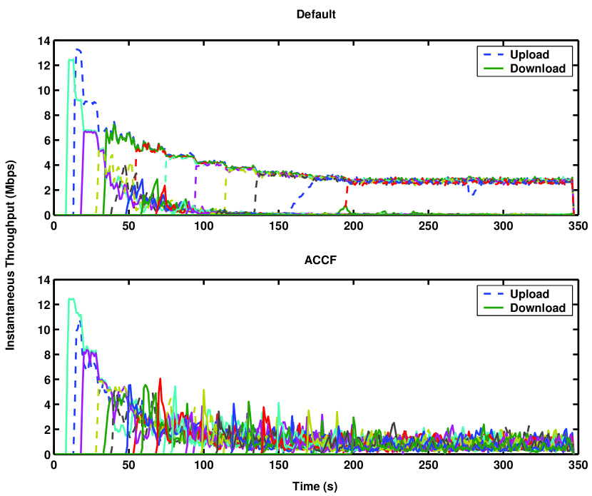
In the second set of experiments, we use a scenario when TCP connections use the delayed TCP ACK mechanism ().
We start download and upload FTP connections in 10 s and 20 s intervals, respectively. Fig. 14 shows the instantaneous throughput for individual TCP flows over simulation duration. As the results imply, in the default case, TCP download connections starve in terms of throughput as the number of TCP upload connections increase. In the meantime, some upload flows experience long delays in starting and achieving high throughput while some do not. On the other hand, using the proposed ACCF scheme, all uplink and downlink TCP flows enjoy fair access. The results are important in showing the proposed algorithm’s effectiveness even when the delayed TCP ACK mechanism is used.
Wireless Channel Errors
In the third set of experiments, we assume the wireless channel to be an Additive White Gaussian Noise (AWGN) channel. On top of the energy-based PHY model of ns-2, we implemented a BER-based PHY model according to the framework presented in [33] using the way of realization in [34]. Our model considers the channel noise power in Signal-to-Noise Ratio (SNR). We set wireless channel noise levels such that each station experience a finite data packet error rate (PER). We repeat the tests for AWGN channel SNR values when PER is 0.001 or 0.01. We only present the results on fairness index for the case when PER is 0.01, since the results slightly differ and a similar discussion holds for the case when PER is 0.001.
As in the first set of experiments, we generate 3, 5, or 10 upload TCP connections and vary the number of download TCP connections from 5 to 30. Fig. 15 shows that the proposed ACCF scheme provides fair access. The performance of ACCF is resilient to wireless channel errors, i.e., fair access is preserved even when there are errors in the wireless channel. As shown in Fig. 16, the throughput drops slightly when compared to errorless wireless channel case due to the MAC retransmissions. Still, high channel utilization maintained. DCF has slightly higher channel utilization at the expense of fair access.
Varying source packet rates among TCP connections
In the forth set of experiments, we test the performance when half of the stations use the FTP agent, while the other half use the Telnet agent with packet rates between 150 Kbps and 550 Kbps.
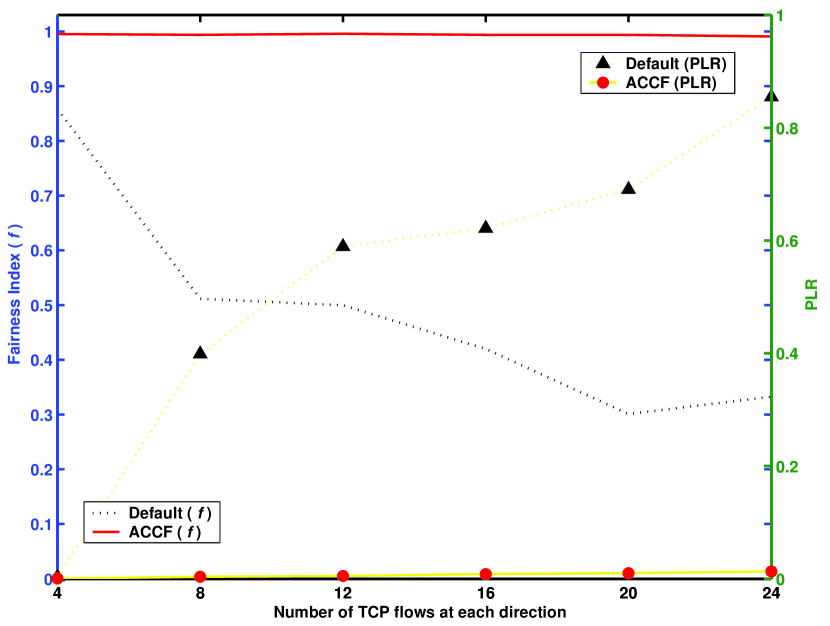
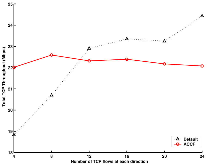
Fig. 17 and Fig. 18 compares the performance in terms of fair access and total throughput for default DCF and ACCF for increasing number of TCP stations in each direction, respectively. In, Fig. 17, the right y-axis denotes the fairness index, , among the FTP (saturated) flows, while the left y-axis denotes the average Packet Loss Rate (PLR) for Telnet (nonsaturated) flows. As the results present, the proposed ACCF scheme can provide fair access (i.e., and ) irrespective of the number of stations. As Fig. 18 shows, high channel utilization is also maintained.
Short-lived TCP flows
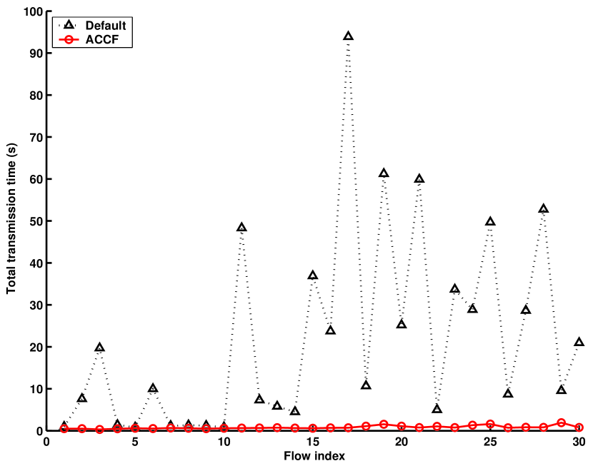
In the fifth set of experiments, we test the performance in terms of short-term fairness. First, we generate 5 uplink and 10 downlink long-lived FTP flows. Then, 15 short-lived uplink and downlink FTP flows are generated with 5 s intervals consecutively. Fig.19 shows the total transmission duration for individual short-lived FTP flows for the proposed ACCF algorithm and the default DCF. Note that the flow indices from 1 to 15 represent uplink FTP flows while flow indices from 16 to 30 represent downlink FTP flows. As the results imply, the short-lived file transfer can be completed in a significantly shorter time when the proposed algorithm is used. We can conclude that the proposed ACCF algorithm is short-term fair. Although not explicitly presented, most of the downlink connections experience connection timeouts and even cannot complete the whole transaction within the simulation duration for the default case.
Varying TCP Congestion Windows among Connections
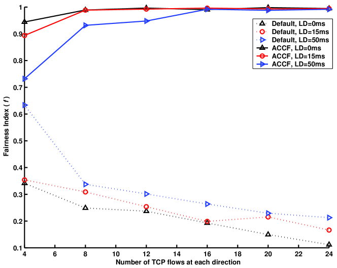
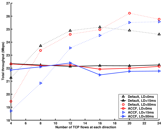
In the sixth set of experiments, we generate TCP connections with receiver advertised congestion window sizes of 12, 20, 42, or 84. We vary the number of FTP connections from 4 to 24 and the wired link delay from 0 to 50 ms. For each scenario, the number of flows using a specific congestion window size is uniformly distributed among the connections (i.e., when there are 12 upload and 12 download TCP flows, 3 of the upload/download TCP connections use the congestion window size W, where W is selected from the set ). The wireless channel is assumed to be errorless. The TCP delayed ACK mechanism is enabled.
Fig. 20 shows the fairness index among all connections. We compare the default DCF results with the results obtained when the AP employs the proposed ACCF. As the results imply, with the introduction of the proposed control block at the AP, a better fair resource allocation can be achieved. However, a perfect fairness is not observed when the link delay is larger and the number of flows is smaller. In these cases, the bandwidth-delay product is larger than the receiver advertised TCP congestion window size for connections with small congestion windows. As a result, the throughput is limited by the congestion window itself, not by the network bandwidth.
In Fig. 21, we plot the total TCP throughput. As the results show, the default DCF has higher channel utilization than ACCF. On the other hand, this comes at the expense of fair access as shown in Fig. 20. Although not explicitly shown in Fig. 21, all TCP downlink flows are shut down when default DCF is employed (see Section II-B). In this case, the shared channel can mainly be utilized by data packets of uplink TCP connections. In a fair scenario, as for ACCF, the TCP ACKs of downlink connections sharing the channel are considerably higher in number than the default DCF. As MAC efficiency decreases when packets of shorter length access the channel, ACCF channel utilization efficiency is slightly lower than DCF. The difference is more notable for higher number of flows, since the AP, which is the main source of short TCP ACK packet transmissions for the default DCF, has a smaller share of the bandwidth.
V Conclusion
In this paper, we focused on unfair TCP access problem in an IEEE 802.11 infrastructure BSS. We have presented a novel and simple analytical model to calculate the TCP congestion window limit that provides fair TCP access in a wired/wireless scenario. The key contribution of this study is that the proposed analytical model considers varying wired link delays among connections, varying number of uplink and downlink connections, and the use of delayed ACK mechanism. Via simulations, we have shown that the congestion window limits calculated via the proposed analysis (FCWA) provides fair TCP access and high channel utilization. The same model can also be used to decide on the required AP buffer size for fair TCP access given the TCP congestion window limits used by the connections. The cycle time analysis can be extended for IEEE 802.11e WLANs [6] as in [28], therefore the analysis in this paper can also be extended for the case when MAC parameter differentiation is used.
We have also designed a novel link layer access control block for the AP that provides fair TCP access in an 802.11 infrastructure BSS. Our simple idea for resolving the unfairness problem in the WLAN is prioritizing TCP data packets of uplink flows over TCP ACK packets of uplink flows at the AP. This idea originates from the main finding of the proposed analytical model which shows that fair access can be achieved by throttling TCP traffic (i.e., limiting congestion windows). The proposed link layer access control block employs an ACK congestion control and filtering (ACCF) algorithm. The proposed ACCF algorithm is unique in that the specific algorithm parameters are based on the measured average data transmission rate at the AP. Via simulations, we show that fair resource allocation for uplink and downlink TCP flows can be provided in a wide range of practical scenarios when the proposed ACCF method is used. A key insight that can be obtained from this study is that fair and efficient TCP access in a WLAN can simply be achieved by intelligently scheduling TCP ACK transmissions at the AP. As an attractive feature, ACCF does not require any changes in the 802.11 standard, nor any enhancement at the stations.
References
- [1] IEEE Standard 802.11: Wireless LAN medium access control (MAC) and physical layer (PHY) specifications, IEEE 802.11 Std., 1999.
- [2] H. Balakrishnan, V. Padmanabhan, and R. H. Katz, “The Effects of Asymmetry on TCP Performance,” ACM Baltzer Mobile Networks and Applications (MONET), 1999.
- [3] D. Chiu and R. Jain, “Analysis of the Increase/Decrease Algorithms for Congestion Avoidance in Computer Networks,” Journal of Computer Networks and ISDN, pp. 1–14, June 1989.
- [4] N. H. Vaidya, P. Bahl, and S. Gupta, “Distributed Fair Scheduling in a Wireless LAN,” in Proc. ACM Mobicom ’00, August 2000.
- [5] T. Nandagopal, T. Kim, X. Gao, and V. Bharghavan, “Achieving MAC Layer Fairness in Wireless Packet Networks,” in Proc. ACM Mobicom ’00, August 2000.
- [6] IEEE Standard 802.11: Wireless LAN medium access control (MAC) and physical layer (PHY) specifications: Medium access control (MAC) Quality of Service (QoS) Enhancements, IEEE 802.11e Std., 2005.
- [7] C. Casetti and C. F. Chiasserini, “Improving Fairness and Throughput for Voice Traffic in 802.11e EDCA,” in Proc. IEEE PIMRC ’04, September 2004.
- [8] D. J. Leith, P. Clifford, D. Malone, and A. Ng, “TCP Fairness in 802.11e WLANs,” IEEE Commun. Lett., pp. 964–966, November 2005.
- [9] J. Freitag, N. L. S. da Fonseca, and J. F. de Rezende, “Tuning of 802.11e Network Parameters,” IEEE Commun. Lett., pp. 611–613, August 2006.
- [10] I. Tinnirello and S. Choi, “Efficiency Analysis of Burst Transmissions with Block ACK in Contention-Based 802.11e WLANs,” in Proc. IEEE ICC ’05, May 2005.
- [11] F. Keceli, I. Inan, and E. Ayanoglu, “Weighted Fair Uplink/Downlink Access Provisioning in IEEE 802.11e WLANs,” in IEEE ICC ’08, Beijing, China, May 2008.
- [12] S. W. Kim, B.-S. Kim, and Y. Fang, “Downlink and Uplink Resource Allocation in IEEE 802.11 Wireless LANs,” IEEE Trans. Veh. Technol., pp. 320–327, January 2005.
- [13] J. Jeong, S. Choi, and C.-K. Kim, “Achieving Weighted Fairness between Uplink and Downlink in IEEE 802.11 DCF-based WLANs,” in Proc. IEEE QSHINE ’05, August 2005.
- [14] S. Pilosof, R. Ramjee, D. Raz, Y. Shavitt, and P. Sinha, “Understanding TCP Fairness over Wireless LAN,” in Proc. IEEE Infocom ’03, April 2003.
- [15] Y. Wu, Z. Niu, and J. Zheng, “Study of the TCP Upstream/Downstream Unfairness Issue with Per-flow Queueing over Infrastructure-mode WLANs,” Wireless Commun. and Mobile Comp., pp. 459–471, June 2005.
- [16] J. Ha and C.-H. Choi, “TCP Fairness for Uplink and Downlink Flows in WLANs,” in Proc. IEEE Globecom ’06, November 2006.
- [17] N. Blefari-Melazzi, A. Detti, I. Habib, A. Ordine, and S. Salsano, “TCP Fairness Issues in IEEE 802.11 Networks: Problem Analysis and Solutions Based on Rate Control,” IEEE Trans. Wireless Commun., pp. 1346–1355, April 2007.
- [18] F. Keceli, I. Inan, and E. Ayanoglu, “TCP ACK Congestion Control and Filtering for Fairness Provision in the Uplink of IEEE 802.11 Infrastructure Basic Service Set,” in Proc. IEEE ICC ’07, June 2007.
- [19] “RFC3449 - TCP Performance Implications of Network Path Asymmetry,” 2002.
- [20] “RFC2760 - Ongoing TCP Research Related to Satellites,” 2000.
- [21] H. Balakrishnan, V. N. Padmanabhan, and R. H. Katz, “The Effects of Asymmetry on TCP Performance,” in Proc. ACM/IEEE MobiCom ’97, November 1997.
- [22] T. V. Lakshman, U. Madhow, and B. Suter, “Window-based Error Recovery and Flow Control with a Slow Acknowledgement Channel: A Study of TCP/IP Performance,” in Proc. IEEE Infocom ’97, April 1997.
- [23] G. Fairhurst, N. K. G. Samaraweera, M. Sooriyabandara, H. Harun, K. Hodson, and R. Donadio, “Performance Issues in Asymmetric TCP Service Provision using Broadband Satellite,” IEE Proc. Commun., pp. 95–99, 2001.
- [24] M. Allman, “On the Generation and Use of TCP Acknowledgements,” ACM Comp. Comm. Review, October 1998.
- [25] L. Kalampouskas, A. Varma, and K. K. Ramakrishnan, “Improving TCP Throughput over Two-Way Asymmetric Links: Analysis and Solutions,” in Proc. ACM Sigmetrics ’98, 1998.
- [26] L. Zhang, S. Shenker, and D. D. Clark, “Observations on the Dyanmics of a Congestion Control Algorithm: The Effects of Two-Way Traffic,” ACM Comp. Comm. Review, pp. 133–147, 1991.
- [27] K. Medepalli and F. A. Tobagi, “Throughput Analysis of IEEE 802.11 Wireless LANs using an Average Cycle Time Approach,” in Proc. IEEE Globecom ’05, November 2005.
- [28] I. Inan, F. Keceli, and E. Ayanoglu, “Performance Analysis of the IEEE 802.11e Enhanced Distributed Coordination Function using Cycle Time Approach,” in Proc. IEEE Globecom ’07, November 2007.
- [29] (2006) The Network Simulator, ns-2. [Online]. Available: http://www.isi.edu/nsnam/ns
- [30] IEEE Standard 802.11: Wireless LAN medium access control (MAC) and physical layer (PHY) specifications: Further Higher Data Rate Extension in the 2.4 GHz Band, IEEE 802.11g Std., 2003.
- [31] R. Jain, The Art of Computer Systems Performance Analysis: Techniques for Experimental Design, Measurement, Simulation, and Modeling. John Wiley and Sons, 1991.
- [32] F. Keceli, I. Inan, and E. Ayanoglu, “Fair TCP Access Provisioning in the IEEE 802.11 Infrastructure Basic Service Set,” Tech. Rep., May 2008.
- [33] D. Qijao and S. Choi, “Goodput Enhancement of IEEE 802.11a Wireless LAN via Link Adaptation,” in Proc. IEEE ICC ’01, June 2001.
- [34] M. Lacage. (2006) Ns-2 802.11 Support. INRIA Sophia Antipolis. France. [Online]. Available: http://spoutnik.inria.fr/code/ns-2