Also at ]Taras Shevchenko National University of Kiev, Ukraine.
Scattering of backward spin waves in a one-dimensional magnonic crystal
Abstract
Scattering of backward volume magnetostatic spin waves from a one-dimensional magnonic crystal, realized by a grating of shallow grooves etched into the surface of an yttrium-iron garnet film, was experimentally studied. Rejection frequency bands were clearly observed. The rejection efficiency and the frequency width of the rejection bands increase with increasing groove depth. A theoretical model based on the analogy of a spin-wave film-waveguide with a microwave transmission line was used to interpret the obtained experimental results.
pacs:
75.50.Gg, 75.30.Ds, 75.40.GbArtificial media with periodic lateral variation of their magnetic properties, so-called magnonic crystals, are the magnetic analogue to photonic and sonic crystals and are suitable for operation in the microwave frequency range. Spectra of spin-wave excitations in magnonic crystals are considerably modified with respect to uniform media and exhibit features such as full band gaps BH Kolodin , where spin waves are not allowed to propagate. Due to the wide tunability of their characteristic properties magnonic crystals offer excellent potential for the investigation of linear and nonlinear spin-wave dynamics MC review .
Both ferromagnetic and ferrite MC review media can be artificially structured for fabrication of magnonic crystals of different dimensionality.
We have chosen a single-crystal ferrite film of yttrium iron garnet (YIG) as the magnetic material because of the extremely small magnetic relaxation. Furthermore, we have focused on one-dimensional magnonic crystals because they allow for operation at only one eigenmode of the film. The latter is determined by the angle between the wave propagation direction and the external magnetic field orientation. Previously, only the surface magnetostatic waves (wave propagation direction is perpendicular to the magnetic field applied in the film plane) and forward magnetostatic waves (external field is oriented perpendicular to the film plane) were studied in magnonic crystals MC review ; MC skyes ; MC MSSW ; MC FVMSW . However, nowadays special attention is focused on spin waves of backward type, so-called backward volume magnetostatic waves (BVMSW), due to their special benefits both for research on nonlinear spin-wave dynamics bulet ; reversal momentum and application convolver ; logic . Here we present experimental and theoretical results on scattering of BVMSW from a structure with periodic changes of the film thickness.
To fabricate the magnonic crystal a 5.5 m-thick YIG film was used which was epitaxially grown along the (111) crystallographic axis. Hot orthophosphoric acid etching and photolithography was used to prepare the grooves. The lithography was based on a standard photoresist AZ 5214E baked by UV irradiation which is stable against hot 160 oC orthophosphoric acid. The mask had parallel lines m in width and spaced 270 m from each other, so the lattice constant was m. The groves were perpendicularly oriented with respect to the spin-wave propagation direction. In order to study the dependence of crystal characteristics on the groove depth the grooves were etched in 100 nm steps from 100 nm to 1 m. The grooves depth was controlled by the etching time and measured using a profilometer. Anisotropic chemical etching caused by the YIG crystallographic structure was observed: the speed of etching parallel to the film plane was approximately ten times larger than in the perpendicular direction, so the final groove depth profile along the direction of wave propagation had a trapezoidal shape.
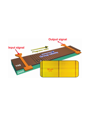
Two microstrip antennae placed 8 mm apart from each other on each side of the magnonic crystal area were used to excite and receive the dipolar spin waves, see Fig. 1. A bias magnetic field of 1845 Oe was applied in the plane of the YIG film stripe along its length and parallel to the direction of spin-wave propagation. Thus the conditions for backward volume magnetostatic wave (BVMSW) propagation are given. The microwave signal power was equal to 1 mW to avoid any non-linear processes.
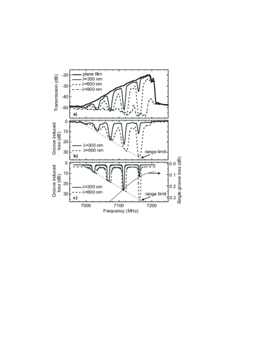
The experimental BVMSW transmission characteristics for the unstructured film as well as for magnonic crystals with = 300, 600 and 900 nm are shown in Fig. 2(a). Figure 2(b) demonstrates groove structure induced losses calculated as a difference between the transmission characteristics for the unstructured and structured films. The dotted straight line indicates the limit of the dynamic range of the experimental setup.
From Fig. 2(b) one sees that the grooves as shallow as 300 nm result in the appearance of a set of rejection bands (or transmission gaps), where spin-wave transmission is highly reduced. According to the condition for Bragg reflection, higher-order rejection bands correspond to larger spin-wave wave numbers. In the case of BVMSW the latter corresponds to lower frequencies. From the depths and the frequency widths of the gaps one sees that the efficiency of the rejection increases with increase in the order of Bragg reflection. This suggests that BVMSW with smaller wavelengths are more sensitive to the introduced inhomogeneities.
Both Fig. 2(a) and 2(b) demonstrate that an increase in leads to an increase in the rejection efficiency and in . A small frequency shift of the minima of transmission towards higher frequencies is observed, as well as an increase in insertion losses in the transmission (i.e. allowed) bands. For nm the insertion loss in the whole spin-wave band is so important that almost no spin-wave propagation is observed (see Fig. 2(a)).
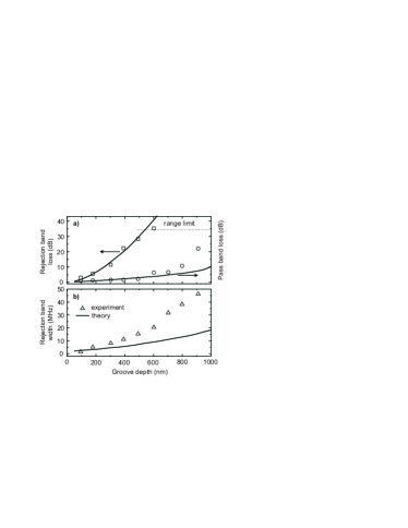
The points in Fig. 3 represent the insertion loss (upper panel) and the frequency width measured for the first transmission gap (the central frequency of the gap is 7160 MHz). This rejection band was chosen because of its largest experimental dynamic range. From Fig. 3(a) one sees that the difference in insertion loss for transmission and rejection bands can reach 30 dB for =0.5 m. With increase in the groove depth the rejected power exceeds the dynamic range of the experimental setup, and the transmission loss cannot be measured. The observed frequency shift of the minimum of transmission with increase in was 10-20 MHz. The maximum rejection band width was almost 50 MHz.
A theoretical description of the scattering of dipole spin waves from inhomogeneities is given by a singular integral equation , where is the dynamic magnetization, is the microwave field of the input antenna, is the tensor of microwave magnetic susceptibility which depends on the spin wave carrier frequency and the magnetic parameters of the film, is the Green’s function of dipole magnetic field, and is the radius vector. The integration is over the volume of the magnetic structure, thus the inhomogeneity of film thickness is taken into account. The quasi-1D dipole field guslienko of the lowest BVMSW thickness mode decays at the distance of a few film thicknesses. Therefore, as the width of the grooves is much smaller than , most of the distance between the consecutive grooves the spin wave travels as an eigenmode of a continuous film of thickness . For these sections the integral equation reduces to a simple formula (see Eq. (50) in kostylev ) which shows that between the grooves the transmitted and reflected waves only accumulate phase and decay (due to intrinsic magnetic damping). Thus, in order to describe formation of stop bands one has to consider scattering of a BVMSW from just one groove. The effect of a set of the grooves is obtained by cascading the structure periods using matrices of scattering T-parameters and taking interference effects into account.
Therefore in this work instead of solving the singular integral equation we considered the magnonic crystal as a periodical sequence of sections of regular transmission lines with different propagation constants (different spin-wave wave numbers) for the same carrier frequency. We neglect the fact that the groove edges are oblique and consider the groove cross-section as a rectangle with the same depth and having the same area. The T-matrix for a section of unstructured film of the length has diagonal components only: , where is the spin-wave wavenumber in the unstructured film, is the rate of spin-wave spatial damping, is the gyromagnetic ratio, is the ferromagnetic resonance linewidth, and is the spin-wave group velocity. Similarly, the T-matrix for a regular spin-wave film waveguide with the thickness is ; , where is the spin-wave damping rate for the groove. Here we used the fact that the BVMSW dispersion law for small wave numbers is practically linear, therefore the spin-wave wave number in the grooves is . To describe the increase in the loss in the pass bands with increase in the groove depth we introduce an empirical parameter which accounts for larger contribution of two-magnon scattering processes in the areas which underwent anisotropic etching etching . Then the damping rate in the grooves can be expressed as .
There are reflections from the junctions of the consecutive sections. The T-matrix for the front edge of the groove is and that for the rear edge is . Therefore the T-matrix for one period of the structure is, as follows: . To obtain the T-matrix for the whole groove sequence on has to raise to the -th power. The reflection coefficient for a junction of two sections of regular waveguides is . Following transm line , the transmission coefficient through the junction is . Then one obtains: ; and ; .
Now one has to specify the form of the reflection coefficient . Here we use the analogy of the change in the film waveguiding properties to a change of characteristic impedance of a microwave transmission line kalinikos . We assume that the change of the characteristic impedance of a spin-wave waveguide because of change of YIG-film thickness is due to change of the film effective inductance. Then the characteristic impedance is linearly proportional to the propagation constant (to the spin-wave wave number in our case), and from Eq. (3) in transm line we arrive at a formula for the reflection coefficient for the wave incident onto the edge of the groove from the unstructured section of the film: .
For the wave incident onto the same junction in the reverse direction which has been already taken into account in the expressions for the T-matrices above. The phenomenological parameter is introduced in this formula to account for eventual factors not taken into account in this simplistic model.
The results of our numerical computation of in the 20-th power are shown in Fig. 2(c) and Fig. 3. One sees that this model is in qualitative agreement with all the tendencies we see in the experiment. In particular, it shows the observed increase in the rejection efficiency with increase in , and the correct behavior of all characteristics of the rejection bands as functions of groove depth .
The formation of transmission gaps is due to multiple reflections from edges of all grooves which form partial standing waves in the space between the grooves. The strength of these reflections is entirely determined by transmission and reflection of a single groove. The latter is shown (in a suitable scale) in Fig. 2(c) for = 300 nm by a dash-dotted continuous line. One sees that the peaks of rejection for the 20-grove structure follow this line. However, the quantitative agreement of this model is poor, unless one introduces a value of considerably larger than 1 (in our calculation ). In particular, for , when the reflection from a grove edge is entirely due to transformation of wavenumber, the model considerably underestimates the depth of transmission gaps. This suggests that other effects such as transformation of modal distribution of dynamic magnetization and eventual generation of other thickness modes (and, possibly, back-transformation) through 2-wave scattering processes give significant contributions to .
In conclusion, in this work we experimentally demonstrated that in the BVMSW configuration a one-dimensional magnonic crystal showed excellent spin-wave signal rejection of more than 30 dB. The width of the rejection bands exceeded the values for the other spin-wave configurations MC review ; MC skyes ; MC MSSW ; MC FVMSW , and could be controlled by the groove depth. A simple model was proposed which is in qualitative agreement with the experimental results.
Financial support by the DFG SE 1771/1-1, Australian Research Council, and the University of Western Australia is acknowledged. Special acknowledgments to Dr. Sandra Wolff and the Nano+Bio Center, TU Kaiserslautern.
References
- (1) P.A. Kolodin and B. Hillebrands, J. Magn. Magn. Mater. 161, 199 (1996).
- (2) K.W. Reed, J.M. Owens, R.L. Carter, Circ. Syst. Signal Process. 4, 157 (1985).
- (3) C.G. Skyes, J.D. Adam, and J.H. Collins, Appl. Phys. Lett. 29, 388 (1976).
- (4) J.P. Parekh and H.S. Tuan, Appl. Phys. Lett. 30, 667 (1977).
- (5) J.P. Parekh and H.S. Tuan, IEEE Trans. Microwave Theory Tech. MTT-26, 1039 (1978).
- (6) A.A. Serga, B. Hillebrands, S.O. Demokritov, A.N. Slavin, P. Wierzbicki, V. Vasyuchka, O. Dzyapko, and A. Chumak, Phys. Rev. Lett. 94, 167202 (2005)
- (7) S.O. Demokritov, A.A. Serga, V.E. Demidov, B. Hillebrands, M. Kostylev, B.A. Kalinikos, Nature 426, 159 (2003)
- (8) Yu.V. Kobljanskyj, G.A. Melkov, A.A. Serga, V.S. Tiberkevich, A.N. Slavin, Appl. Phys. Lett. 81, 1645 (2002)
- (9) M.P.Kostylev, A.A.Serga, T.Schneider, B.Leven, B.Hillebrands, Appl. Phys. Lett. 87, 153501 (2005)
- (10) K.Yu. Guslienko, S.O. Demokritov, B. Hillebrands, and A.N. Slavin, Phys. Rev. B 66, 132402 (2002).
- (11) M.P. Kostylev, A.A. Serga, T. Schneider, T. Neumann, B. Leven, B. Hillebrands, and R.L. Stamps, Phys. Rev. B 76, 184419 (2007)
- (12) J. Basterfield, J. Phys. D: Appl. Phys. 2, 1159 (1969).
- (13) W. Berry, IEEE Trans. Microwave Theory Tech. MTT-34, 80 (1986).
- (14) B.A. Kalinikos, private communication.