Electrical generation of pure spin currents in a two-dimensional electron gas
Abstract
Pure spin currents are measured in micron-wide channels of GaAs two-dimensional electron gas (2DEG). Spins are injected and detected using quantum point contacts, which become spin polarized at high magnetic field. High sensitivity to the spin signal is achieved in a nonlocal measurement geometry, which dramatically reduces spurious signals associated with charge currents. Measured spin relaxation lengths range from 30m to 50m, much longer than has been reported in GaAs 2DEG’s. The technique developed here provides a flexible tool for the study of spin polarization and spin dynamics in mesoscopic structures defined in 2D semiconductor systems.
pacs:
73.23.-b 72.25-bInterest in the physics of spin in solid state devices is driven both by the technological promise of spin electronics, and by the insights that may be gained by using spin currents as a probe into interacting electron systems.Wolf et al. (2001); Zutic et al. (2004) Optical spin current measurements have advanced our understanding of spin relaxation, accumulation and separation via spin-orbit interaction in a variety of bulk semiconductors and quantum wells.Kikkawa et al. (1997); Kato et al. (2004); Crooker et al. (2005); Sih et al. (2005, 2006); Holleitner et al. (2006); Weber et al. (2007); Meier et al. (2007) Spin currents can also be generated and detected electrically using spin-selective contacts, enabling straightforward integration into circuits where device geometry and spin parameters are controlled by gates.Johnson and Silsbee (1985); Jedema et al. (2001); Potok et al. (2002); Folk et al. (2003); Rokhinson et al. (2004); Valenzuela and Tinkham (2006); Tombros et al. (2007); Koop et al. (2008)
Devices defined by electrostatic gates in GaAs/AlGaAs two-dimensional electron gases (2DEG’s) display an extraordinary variety of spin-related phenomena, showing promise for quantum dot-based quantum information processing, coherent spin rotations mediated by spin-orbit interaction, even the possibility of spontaneous spin polarization in quantum point contacts.Nowack et al. (2007); Thomas et al. (1996) These structures are typically studied using direct measurements of the charge currents passing through them.Folk et al. (2003); Hanson et al. (2004); Rokhinson et al. (2004) The sensitivity to spin properties can be greatly enhanced by measuring pure spin currents resulting from spin-resolved charge transport, but such measurements have not yet been integrated with gate-defined mesoscopic devices.Johnson and Silsbee (1985)
In this Letter, we present electrical measurements of pure spin currents in micron-wide channels of a GaAs 2DEG using one-dimensional constrictions known as quantum point contacts (QPC’s) as injectors and detectors.van Wees et al. (1988); Wharam et al. (1988) The ability to change the channel geometry in-situ using gate voltages enabled an accurate measurement of spin relaxation length even for small contact polarizations. The relaxation lengths observed in this work, , are significantly longer than the values typically reported in GaAs 2DEG’s because spin-orbit mediated relaxation was suppressed by the external magnetic field.Miller et al. (2003); Ivchenko (1973); Duckheim and Loss (2007) The temperature- and field-dependences of the spin current polarization were used to extract a Lande g-factor in the QPC’s, , that is enhanced compared to in the bulk.Thomas et al. (1996) An advantage of this polarization-based g-factor measurement is that it does not depend on the interpretation of QPC conductance features.
Pure spin currents are generated electrically through a sequence of two processes. First, charge is injected across a spin-selective barrier, creating a higher population of one spin. Next, the nonequilibrium spin population that accumulates outside of the injector diffuses towards a large electrically floating reservoir with spins in equilibrium. Experimental realizations of this technique often rely on ferromagnetic contacts,Johnson and Silsbee (1985); Jedema et al. (2001); Valenzuela and Tinkham (2006); Lou et al. (2007) but injection from ferromagnets into GaAs 2DEG’s remains a challenge. QPC’s in Tesla-scale magnetic fields are a natural alternative because they are defined within the 2DEG itself.van Wees et al. (1988); Wharam et al. (1988) In contrast to ferromagnets, the polarization axis of a QPC is aligned with the external magnetic field so no Hanle precession of spin currents is expected.
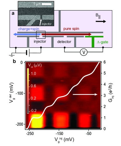
Figure 1(a) shows a schematic of the measurement. A voltage, , is applied across a spin-selective injector QPC driving polarized current, , into the center of a long channel. The spin population that accumulates above the injector diffuses toward the large 2DEG reservoirs at the left and right ends of the channel. All charge current flows to the electrical ground at the left end of the channel; pure spin current flows to the right. The detector QPC, located a distance to the right of the injector, measures the nonlocal voltage, , due to spin accumulation generated by the pure spin current.
The devices were defined using electrostatic gates on the surface of a [001] GaAs/AlGaAs heterostructure. The 2DEG was 110 nm below the surface, with electron density and mobility measured at . The data in this paper are from three channels, each along the [110] crystal axis, with lithographic width and length . The injector and detector spacing ranged from . Lock-in measurements in a dilution refrigerator were performed in magnetic fields, , applied along the channel axis. To avoid trajectories dominated by skipping orbits, the out-of-plane component, , was kept under , ensuring that the cyclotron radius was greater than the channel width. The effective sheet resistance in the channel, , depended on cooldown conditions. The resistance increased by 10-20% from to .
Gate voltages control QPC conductance, , and polarization, . is quantized in units of at high magnetic field, as spin-resolved one-dimensional subbands are added one by one. The first () plateau corresponds to fully polarized transmission, , as only a single spin-up subband is allowed through the QPC (). The second () plateau corresponds to unpolarized transmission, (one spin-up and one spin-down subband); the third corresponds to (two spin-up and one spin-down subband), etc.
Nonlocal signals measured at high magnetic field had a characteristic signature of spin currents, see Fig.1(b). Positive voltages indicating a non-equilibrium spin population above the detector were observed when both contacts were spin-selective, i.e. when both were tuned to odd conductance plateaus (, = , , etc.). The voltage was near zero when both the detector and the injector were set to even plateaus (, = , , etc.). A small negative voltage was often observed when only the injector or only the detector was polarized (e.g., [, ] or [, ]). The origins of the negative signal are currently under investigation.
The spin signal depends in general on a combination of diffusion, spin relaxation, and contact polarization. The expected magnitude of the nonlocal voltage can be calculated from a 1D diffusion equation with boundary conditions of equilibrium polarization at the left and right ends of the channel (distances and from the injector), and including spin relaxation characterized by length :
| (1) |
where is the channel width.
One way to measure spin relaxation length is to compare across several detectors at different positions along the channel. But this technique relies on identical detector polarizations—not necessarily the case for QPC’s at intermediate values of and finite temperature. The flexibility of the gate-defined geometry enabled a measurement of spin relaxation length that was independent of and .
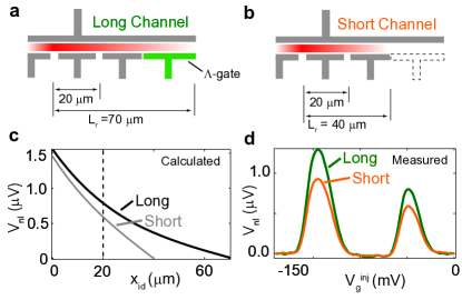
The bottom wall of the channel to the right of the detector was defined by two gates, see Fig.1(a). Undepleting the -gate shortens the right side of the channel, bringing the right-hand equilibrium spin reservoir closer to the detector (Figs.2(a),(b)) and causing a faster drop in the spin-up chemical potential along the channel (Fig.2(c)). If the spin current has relaxed before reaching the -gate, the effect of undepleting the -gate is negligible. But for a channel with , the nonlocal signal decreases when the -gate is undepleted (Fig.2(d)), and can be extracted from the ratio of the signals for long and short channels using Eq.(1). Different channels and different cooldowns gave values of that ranged from to , and were independent of field and temperature from and .
The primary cause of spin relaxation in high-mobility GaAs 2DEG’s is a trajectory-dependent effective magnetic field, , arising from spin-orbit interaction.Dyakonov and Perel (1972) Spin relaxation by this mechanism is, in general, suppressed in a large external magnetic field, .Ivchenko (1973); Duckheim and Loss (2007) Monte Carlo simulations of spin dynamics due to a spin-orbit field were made using the channel geometry from this work and considering a range of spin-orbit parameters.Lüscher et al. (unpublished) [110]-oriented spins relax due to the component of along the [1̄10] axis; the simulations suggest an upper limit [1̄10]1.5T in order to find over the field range . In contrast to the experimental results, the simulations also show to be strongly dependent on the external field, rising to greater than at . Other spin relaxation mechanisms may limit the measured and account for the discrepancy.Elliott (1954)
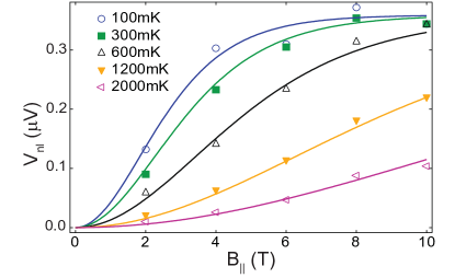
Spin current measurements can be used to quantify spin-selective transmission of the injector and detector. A simple model of a QPC is a saddle point potential barrier that couples two leads with thermally-broadened Fermi distributions and Zeeman-split spin populations. In general, QPC polarization approaches when Zeeman energy is much larger than both thermal broadening and tunnel broadening . Polarization results from different spin-resolved conductances: , with subband cutoff energy and transmission . The evolution of the spin signal in magnetic field and temperature (Fig.3) is consistent with a constant relaxation length and QPC polarization that would be expected from the saddle point model with g-factor and tunnel broadening (Fig.3). Similar g-factors were found for all devices. Enhanced g-factors extracted from conductance signatures (rather than QPC polarization) have previously been ascribed to stronger exchange interaction at low density.Thomas et al. (1996)
Nonlocal voltages unrelated to spin accumulation were also observed. Fluctuations due to quantum interference were superimposed on the spin signal, but were within experimental noise for or .Skocpol et al. (1987) Joule and Peltier heating of the channel by the injected current gave rise to a temperature difference across the detector, , that led to thermoelectric contributions to the nonlocal voltage.Molenkamp et al. (1990, 1992) Signals due to Joule heating did not interfere with the spin signal because they appeared at the second harmonic () of the lock-in excitation, , where is the thermopower of the detector QPC.
In contrast to Joule heating, Peltier heating appears at the first harmonic () of the excitation: , and was more difficult to distinguish from the spin signal. An identifying characteristic of the spin signal was its magnetic field dependence: the spin component was significantly larger than the thermoelectric voltage for , but the distinction was ambiguous at lower fields. A nonlocal signal that remained clearly visible down to zero field in the experiment motivated a more careful analysis of the thermoelectric contribution.
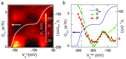
Figure 4(a) illustrates the similarity between spin and thermal signatures at low magnetic field (cf. Fig.1(b)). QPC thermopower is zero on conductance plateaus, but finite at the transitions between plateaus as well as on the so-called 0.7 structure that is commonly observed at low field.Molenkamp et al. (1990); Thomas et al. (1996); Appleyard et al. (2000) Finite thermopower for injector and detector near the steps in conductance gives rise to a Peltier signal in a checkerboard pattern that is reminiscent of the spin signal. The thermoelectric origin of the signal in Fig.4(a) is supported by a comparison of the zero-field signals at and (Fig.4(b)). The signal is proportional to Joule heating by the injected current and to the thermopower of the detector, and serves as a fingerprint of thermal effects. The signal shows a nearly identical gate voltage dependence to the signal, suggesting that it is also thermal. The signal can be used to extract the thermoelectric sensitivity of the detector QPC to heating: at the first detector conductance step. Assuming that the signal is due entirely to Peltier heating through the injector, the magnitude of the signal at the first injector and detector conductance steps implies at , consistent with previous measurements.Molenkamp et al. (1990, 1992); Appleyard et al. (1998)
Spin selectivity of QPC’s at zero magnetic field has been linked to 0.7 structure in earlier experiments.Thomas et al. (1996); Rokhinson et al. (2006) The analysis above shows that the data in Fig.4(a) may be explained without invoking a spontaneous spin polarization. It does not rule out a small additional contribution due to spin, but no direct evidence for zero-field spin polarization was observed. For example, Hanle precession due to milliTesla-scale external fields would have been expected if the polarization axes of the QPC’s were fixed by an intrinsic broken symmetry. If the polarization axes were not fixed, an increase in the signal might have been expected as uncorrelated axes were aligned by a small external magnetic field. To look for these effects, small fields were applied along [110] and [1̄10], but no change in the signal was observed up to several hundred milliTesla, where conventional QPC polarization sets in.
In conclusion, pure spin currents travel for tens of microns in micron-wide channels of 2DEG, and provide a valuable probe of spin relaxation and spin polarization in mesoscopic structures. In the future, spin-orbit anisotropy in GaAs 2DEGs will be explored by rotating the channel axis and the direction of the external in-plane magnetic field.
Acknowledgements: The authors thank M. Duckheim, J.C. Egues, D. Loss, S. Lüscher, and G. Usaj for valuable discussions. Work at UBC supported by NSERC, CFI, and CIFAR. W.W. acknowledges financial support by the Deutsche Forschungsgemeinschaft (DFG) in the framework of the program “Halbleiter-Spintronik” (SPP 1285).
References
- Wolf et al. (2001) S. A. Wolf et al., Science 294, 1488 (2001).
- Zutic et al. (2004) I. Zutic, J. Fabian, and S. Das Sarma, Rev.Mod.Phys. 76, 323 (2004).
- Kikkawa et al. (1997) J. M. Kikkawa et al., Science 277, 1284 (1997).
- Kato et al. (2004) Y. K. Kato et al., Science 306, 1910 (2004).
- Crooker et al. (2005) S. A. Crooker et al., Science 309, 2191 (2005).
- Sih et al. (2005) V. Sih et al., Nat. Physics 1, 31 (2005).
- Sih et al. (2006) V. Sih et al., Phys.Rev. Lett. 97, (2006).
- Holleitner et al. (2006) A. W. Holleitner et al., Phys. Rev. Lett. 97, (2006).
- Weber et al. (2007) C. P. Weber et al., Phys. Rev. Lett. 98, (2007).
- Meier et al. (2007) L. Meier et al., Nat. Phys. 3, 650 (2007).
- Johnson and Silsbee (1985) M. Johnson and R. H. Silsbee, Phys. Rev. Lett. 55, 1790 (1985).
- Jedema et al. (2001) F. J. Jedema, A. T. Filip, and B. J. van Wees, Nature 410, 345 (2001).
- Potok et al. (2002) R. M. Potok et al., Phys. Rev. Lett. 89, (2002).
- Folk et al. (2003) J. A. Folk et al., Science 299, 679 (2003).
- Rokhinson et al. (2004) L. P. Rokhinson et al., Phys. Rev. Lett. 93, (2004).
- Valenzuela and Tinkham (2006) S. O. Valenzuela and M. Tinkham, Nature 442, 176 (2006).
- Tombros et al. (2007) N. Tombros et al., Nature 448, 571 (2007).
- Koop et al. (2008) E. Koop et al., arXiv:0801.2699 (2008).
- Nowack et al. (2007) K. C. Nowack et al., Science 318, 1430 (2007).
- Thomas et al. (1996) K. J. Thomas et al., Phys. Rev. Lett. 77, 135 (1996).
- Hanson et al. (2004) R. Hanson et al., Phys. Rev. B 60, R241304 (2004).
- van Wees et al. (1988) B. J. van Wees et al., Phys. Rev. Lett. 60, 848 (1988).
- Wharam et al. (1988) D. A. Wharam et al., Journ. of Phys. C-Solid State Phys. 21, L209 (1988).
- Miller et al. (2003) J. B. Miller et al., Phys. Rev. Lett. 90, (2003).
- Ivchenko (1973) E. L. Ivchenko, Fiz. Tverd. Tela. 15, 1566 (1973).
- Duckheim and Loss (2007) M. Duckheim and D. Loss, Physical Review B 75, (2007).
- Lou et al. (2007) X. H. Lou et al., Nat.Phys. 3, 197 (2007).
- Dyakonov and Perel (1972) M. I. Dyakonov and V. I. Perel, Sov. Phys. Solid State 13, 3023 (1972).
- Lüscher et al. (unpublished) S. Lüscher, S. M. Frolov, and J. A. Folk (unpublished).
- Elliott (1954) R. Elliott, Phys. Rev. 96, 226 (1954).
- Skocpol et al. (1987) W. J. Skocpol et al., Phys. Rev. Lett. 58, 2347 (1987).
- Molenkamp et al. (1990) L. W. Molenkamp et al., Phys.Rev.Lett. 65, 1052 (1990).
- Molenkamp et al. (1992) L. W. Molenkamp et al., Phys.Rev.Lett. 68, 3765 (1992).
- Appleyard et al. (2000) N. J. Appleyard et al., Phys. Rev. B 62, R16275 (2000).
- Appleyard et al. (1998) N. J. Appleyard et al., Phys.Rev.Lett. 81, 3491 (1998).
- Rokhinson et al. (2006) L. P. Rokhinson, L. N. Pfeiffer, and K. W. West, Phys. Rev. Lett. 96, (2006).