Transient electric fields in laser plasmas observed by proton streak deflectometry
Abstract
A novel proton imaging technique was applied which allows a
continuous temporal record of electric fields within a time window
of several nanoseconds. This ”proton streak deflectometry” was
used to investigate transient electric fields of intense ( W/cm2) laser irradiated foils. We found out that
these fields with an absolute peak of up to V/m extend over
millimeter lateral extension and decay at nanosecond duration.
Hence, they last much longer than the ( ps) laser
excitation, and extend much beyond the laser irradiation focus.
The following article has been submitted to Applied
Physics Letters. After it is published, it will be found at
http://apl.aip.org/.
Laser proton acceleration is a rapidly emerging field with yet unknown potential for beam specifications and applications. The typical properties of the generated proton and ion beams are picosecond emission, low longitudinal and transversal emittance and in many cases a broad and continuous kinetic energy distribution Hatchett et al. (2000); Borghesi et al. (2004, 2003); Romagnani et al. (2005); Toncian et al. (2006). These properties are almost exclusively determined by the geoemtrical and temporal structure of the accelerating electric field, created by the laser accelerated electrons. In this context the recently observed phenomenon of transient electric fields with large lateral extension (of the order of millimeters) has gained considerable attention Toncian et al. (2006). Such extension exceeds the initial laser spot size considerably, hence, the phenomenon of lateral electron transport McKenna et al. (2007) needs to be investigated for the complete understanding of transient field geometries.
We employ a modified and extended version of the recently developed method of proton beam deflectometry Borghesi et al. (2003) and demonstrate this in a similar experiment to Romagnani et al. (2005) with lower laser irradiance. If the proton beam is detected with a velocity dispersive detector (e.g. a magnetic spectrometer) the influence of the transient fields on the protons can be traced back in time because protons with a specific energy arrive at the object to probe at a definite time. Thus the velocity dependent detection of such a proton beam can be named as ”proton streak deflectometry”. The advantage of this method is the possibility of continuous recording of transient fields on a ps time scale. In the presented experiments the selected time window was about several nanoseconds with a time resolution of about 30 ps.
In this work a proton beam streak technique is applied for the first time to investigate the electric fields occurring at the rear side of a laser irradiated thin metal foil. Two synchronized high intensity laser at the Max-Born-Institute were employed for the experiment. A high intensity ( W/cm2) 40 fs Ti:Sapphire laser (CPA1) was used to produce the proton beam by irradiating aluminium foils targets of 12 m thickness which are naturally covered with a water and hydro-carbon contamination layer serving as a proton source. The second laser, a Nd:glass laser (CPA2), was used to produce a second plasma which is to be probed. This laser provides 1.5 ps laser pulses at a peak power of about 5 TW and is synchronized to the CPA1 laser with an accuracy of about 3 ps. The set-up of the experiment and the spectrometer are depicted in Fig. 1.
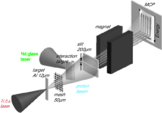
The interaction target, a curved aluminium foil of 12 m thickness, was mounted as a stripe of about 8-10 mm width and bent with a radius of about 5 mm. The CPA2 laser irradiated the concave side and the proton beam probed the rear of the target at 90∘ to the target normal at the CPA2 interaction point. The axis of the interaction target was at a distance of 40 mm from the proton beam source. A mesh with a spacing of 50.8 m intersected the beam at a distance of 30 mm from the source. Two imaging set-ups were employed: one with an entrance slit of 200 m width to the magnetic spectrometer (set-up 1) and one in which the entrance slit and the magnet were removed (set-up 2). The slit to the spectrometer was placed on-axis to the Nd:glass laser interaction point with an accuracy of . The magnification of the interaction area was 16 fold in set-up 1 and 14 fold in set-up 2. The MCP detector Schreiber et al. (2006) and the phosphorous screen were gated in time in order to select protons with a suitable time of flight (e.g. an applied 4 ns gating selected protons with (1.4 - 2) MeV). The gating allowed us to take snapshots in a way that is similar to the detection with film stacks Borghesi et al. (2003); Romagnani et al. (2005) where protons of the same energy are all stopped in the same layer which is almost exclusively exposed by these protons.
The transient field is generated at the rear side of a laser-irradiated foil and hence the proton deflection relates to the field strength which depends on the intensity of the incident laser pulse. Along the x-axis the protons are dispersed according to the velocity (energy) which determines the arrival time of the probe pulse at the interaction target. In order to trace the proton deflection perpendicular to the dispersion direction the proton beam is intersected by a mesh. Each beamlet corresponds to a small part of the proton beam which passes the interaction target at a defined distance and its deflection can be projected to the detector. This is possible due to the transverse laminarity of our proton beam having an emittance value of 5 mm mrad (method cf. Borghesi et al. (2004)) for proton energy above 1 MeV. Fig. 2 (a)
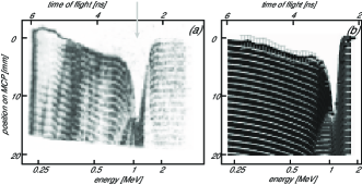
shows the ”streaked” deflection of the proton traces when the CPA2 pulse irradiates the interaction target at intensities of W/cm2 (2.3 J pulse energy). In Fig. 2 (a) the sharp high energy cut-off of the protons sets the maximum energy and the minimum is set by the MCP gating. Both lasers are synchronized such, that the growth and the decay of the deflecting field can be observed.
We analyzed our measurement with an analytical model. The model is based on an empirical construction of two electrical fields which change in space and time in order to explain the measured proton beam deflection. As to be discussed in the following the parameters suggest that these two fields can be associated with an accelerated ion front Romagnani et al. (2005) and a background charge Beg et al. (2004). Intensity and energy of the laser are used to deduce an energetic electron population which propagates through the target, spreads on the rear side and accounts for the field generation. The proton ray-tracing is calculated in 3D geometry and the final result is presented in Fig.2 B. Additionally to the simulation result extracted deflection data are inserted. The size of the error bars is caused by shot to shot fluctuations of the proton beam pointing Schreiber et al. (2006) which occur at energies below 0.8 MeV. The variation of the pointing has been calculated from 10 shots using CPA1 only.
As the experimental results suggest we calculate the deflection with electric fields directed along the y-axis (cf. Fig. 1). Without the entrance slit and the magnet (set-up 2), two-dimensional snapshots of the deflected proton beam show that the proton beam is diverted along the y- axis because the grid-lines along y almost appear undistorted whereas the grid-lines along the x-axis are shifted and compressed along y and thus no longer visible. Furthermore we rely on the assumption that magnetic fields which accompany an electron sheath are in first order circular, with a symmetry axis parallel to the target normal. Hence the action to the proton beam, traversing the magnetic field perpendicular to its axis in a symmetrical ideal case can be neglected.
The strong field component (Field 1) - a field front which decays while propagating - causes a strong deflection of protons passing the 2nd target near by and a decreasing deflection of protons passing the 2nd target at larger distance. This feature is visible at the rising edges and the maximum deflection (peak) of the proton traces in the experiment (cf. Fig. 2 (a)) and in the model traces in Fig. 2 (b). The weaker field component (Field 2) - a coulomb field produced by the charge on the cylinder surface - shifts the proton traces regardless to their incoming original position on y-axis by a similar value gerthsen (1995). This is visible at the lower energetic part of the experimental traces as shown in Fig. 2 A and in the model traces in Fig. 2 (b). The combination of both describes the whole recorded experimental picture. Taking the fluctuations into account the determination of the strength of Field 1 and Field 2 is subjected to an error of about 7 and 20 , respectively. The identified properties of Field 1 are similar to those fields which occur during an ion front expansion. The 2D grid picture supports the occurrence of two different fields: In the color coded picture the yellow line is an area of an enhanced proton number density caused by Field 1 while the shift and blurring of the target edge can be attributed to Field 2.
Field 1 was constructed by modelling a one dimensional plasma expansion into vacuum according to Romagnani et al. (2005) and Mora (2003). Spatially, the electric field shows a plateau region which is followed by an exponential rise up to the peak at the front and then decays as ( where l is the field scale length and r is the distance to the ion front. The field front moves away from the target surface while the electric field in the plateau region decays as ( whereas at the peak and the subsequent region the field decays as (where is the decay time). Field 2 is the field of a charged cylinder and it is supposed to be shielded by the charge cloud accompanying the field front and thus to influence only particles between the target surface and the front. The electrons involved in the plasma expansion, assumed by the scaling law given in fuchs (2006) with a temperature of roughly 100 keV and carrying about 7.5 of the focused laser energy MS1995 (1995), spread over the rear side of the target with a Gaussian density distribution of about 6 mm FWHM. From the experimental 2D spatially resolved pictures (cf. Fig. LABEL:fig3) it is visible that the distribution extends over several mm. Correspondingly the simulation of the traces shows that smaller or lager distributions can not account for the observed deflection function. The field scale length (l) was supposed to be 100 m, similar to Romagnani et al. (2005). The following parameters could be also fitted to the experimental data: the decay time (3 ps) of Field 1, the front propagation velocity ( m/s), the maximum charge density (Field 2) on the target surface ( C/m2), the linear grow within 10 ps and the exponential decay time (600 ps) of the target charge. At t = 0 Field 1 dominates and peaks at the target surface at about V/m.
In summary we have demonstrated a novel imaging method, ”proton streak deflectometry”, which allows measurements of the real-time dynamics of transient intense fields in laser plasma interactions. In particular we have investigated transient fields on the rear of a laser irradiated metal foil which are responsible for the process of laser proton acceleration. The observed streak images were qualitatively explained by the temporal and 1D-spatial development of two electric fields arising from charge-up and charge compensation at a nanosecond timescale, and ion front propagation at a timescale of several hundreds of picoseconds. From that we conclude that we observed effects of energetic electron generation and extended lateral transport which leads to transient electric fields ( V/m) with mm lateral extension. Acknowledgement: This work was partly supported by DFG - Sonderforschungsbereich Transregio TR18 and GRK 1203.
- Hatchett et al. (2000) S. P. Hatchett, C. G. Brown, T. E. Cowan, E. A. Henry, J. S. Johnson, M. H. Key, J. A. Koch, A. B. Langdon, B. F. Lasinski, R. W. Lee, A. J. Mackinnon, D. M. Pennington,, M. D. Perry, T. W. Phillips,, M. Roth, T. C. Sangster,, M. S. Singh, R. A. Snavely, M. A. Stoyer, S. C. Wilks, K. Yasuike, Phys. Plasmas 7, 2076 (2000).
- Borghesi et al. (2004) M. Borghesi, A. J. Mackinnon, D. H. Campbell, D. G. Hicks, S. Kar, P. K. Patel, D. Price, L. Romagnani, A. Schiavi, O. Willi, Phys. Rev. Lett. 92, 055003 (2004).
- Borghesi et al. (2003) M. Borghesi, L. Romagnani, A. Schiavi, D. H. Campbell, M. G. Haines, O. Willi, A. J. Mackinnon, M. Galimberti, L. Gizzi, R. J. Clarke, S. Hawkes, Appl. Phys. Lett. 82, 1529 (2003).
- Romagnani et al. (2005) L. Romagnani, J. Fuchs, M. Borghesi, P. Antici, P. Audebert, F. Ceccherini, T. Cowan, T. Grismayer, S. Kar, A. Macchi, P. Mora, G. Pretzler, A. Schiavi, T. Toncian, O. Willi, Phys. Rev. Lett. 95, 195001 (2005).
- Toncian et al. (2006) T. Toncian, M. Borghesi, J. Fuchs, E. d’Humieres, P. Antici, P. Audebert, E. Brambrink, C. A. Cecchetti, A. Pipahl, L. Romagnani, O. Willi, Science 312, 410 (2006).
- McKenna et al. (2007) P. McKenna, D. C. Carroll, R. J. Clarke, R. G. Evans, K. W. D. Ledingham, F. Lindau, O. Lundh, T. McCanny, D. Neely, A. P. L.Robinson, L. Robson, P. T. Simpson, C. G. Wahlstrom, M. Zepf, Phys. Rev. Lett. 98, 145001 (2007).
- Schreiber et al. (2006) J. Schreiber, S. Ter Avetisyan, E. Risse, M. P. Kalachnikov, P. V. Nickles, W. Sandner, D. Schramm, U. Habs, J. Witte, M. Schnurer, Phys. Plasmas 13, 033111 (2006).
- Beg et al. (2004) F. N. Beg, M. S. Wei, A. E. Dangor, A. Gopal, M. Tatarakis, K. Krushelnick, P. Gibbon, E. L. Clark, R. G. Evans, K. L. Lancaster, P. A. Norreys, K. W. D. Ledingham, P. McKenna, M. Zepf, Appl. Phys. Lett. 84, 2766 (2004).
- gerthsen (1995) P. H. Vogel, Gerthsen Physik, (Springer, Berlin-Heidelberg-New York, 1995), 18. edition ,p. 1074-1075.
- Mora (2003) P. Mora, Phys. Rev. Lett. 90, 185002 (2003).
- fuchs (2006) J. Fuchs, P. Antici, E d’Humieres, E. Lefebvre, M. Borghesi, E. Brambrink, C. A. Cecchetti, M. Kaluza, V. Malka, M. Manclossi, S. Meyroneinc, P. Mora, J. Schreiber, T. Toncian, H. Pepin, R. Audebert, Nature Physics 2, 48-54 (2006).
- (12) M. Schnürer, M. P. Kalachnikov, P. V. Nickles, W. Sandner, Th. Schlegel, W. Sandner, N. Demchenko, R. Nolte, P. Ambrosi, Phys. Plasmas 2, 3106-3110 (1995).