On the Properties of Plastic Ablators in Laser-Driven Material Dynamics Experiments
Abstract
Radiation hydrodynamics simulations were used to study the effect of plastic ablators in laser-driven shock experiments. The sensitivity to composition and equation of state was found to be 5-10% in ablation pressure. As was found for metals, a laser pulse of constant irradiance gave a pressure history which decreased by several percent per nanosecond. The pressure history could be made more constant by adjusting the irradiance history. The impedance mismatch with the sample gave an increase in the pressure transmitted into the sample, for a reduction of several tens of percent in the duration of the peak load applied to the sample, and structured the release history by adding a release step to a pressure close to the ablation pressure. Algebraic relations were found between the laser pulse duration, the ablator thickness, and the duration of the peak pressure applied to the sample, involving quantities calculated from the equations of state of the ablator and sample using shock dynamics.
pacs:
07.35.+k, 52.38.Mf, 47.40.Nm, 79.20.DsI Introduction
Studies of the properties and response of matter under extreme conditions rely increasingly on lasers to induce dynamic loading by ablation. Compared with the canonical technique of impact-induced shocks, laser ablation is more convenient for studying phenomena on shorter time scales (nanoseconds rather than microseconds), for investigating the properties of single crystals and the basic microstructural processes, and for developing new diagnostics. However, laser ablation has potential disadvantages including uncertainties in loading history, spatial variations in irradiance from speckles or the overall intensity envelope, and the possibility of heating the sample under investigation by hot electrons or Bremsstrahlung x-rays. A thorough understanding of the processes of ablative loading is necessary to assure that the response of the sample can be distinguished from phenomena associated with the ablation process.
In many experiments, dynamic loading can be induced by ablation of the sample material itself. Previous studies have demonstrated that spatial variations and preheat were negligible, for ablatively-generated shocks from 100 MPa to 1 TPa in elements Swift_elements_04 and compounds Swift_alloys_04 , and for ramp compression Swift_lice_05 . In other experiments, it is highly desirable to use the laser energy to ablate a well-controlled layer of a different material, in contact with the sample. Advantages of a separate ablator include the ability to restrict multi-electron-volt ablation temperatures to elements of low atomic number irrespective of the sample material, reducing the risk of generating hard x-rays; smoothing of small-scale spatial variations by beam dispersion, radiation transport, and mechanical equilibration within the ablation plasma; and the ability to use a single ablator of known plasma properties for experiments on less well-understood sample materials. A current interest in dynamic loading experiments is the use of x-ray diffraction to study the sample material in the compressed state Remington06 . With ramp compression, the material of highest compression is closest to the ablation surface, so it is desirable to pass the x-rays in and out through the ablator and the ablation plume. It is thus particularly desirable to restrict the ablator to elements of low atomic number, dissimilar to the sample. When the sample material is ablated directly, heat conduction from the plasma and re-condensation of ablated material at the end of the laser pulse can lead to material with a locally different microstructure Peralta05 , an added complication when interpreting the microstructure of recovered samples. A dissimilar ablator acts as a palliative in this case. By appropriate choice of material, an ablator may also increase the efficiency of conversion of laser energy to pressure in the sample.
An ablator layer can however complicate dynamic loading experiments. The time at which the load is first applied to the sample depends on the ablator thickness and the laser irradiance. The mechanical impedance mismatch between the ablator and the sample causes wave interactions, leading to multiple waves in the sample which must be discriminated from the response of the sample. If the composition and properties of the ablator material are not adequately known, it introduces additional uncertainty in the experiments.
Plastics are attractive ablator materials as they are stable to handle and readily available with compositions of low atomic number, such as polystyrene (C8H8)n and polyparaxylylene-N (parylene-N) (C8H8)n, and polyethene (C2H4)n. Deposition and coating techniques exist which can produce layers of uniform and well-characterized thickness Powell66 ; Mattox98 . Polystyrene and parylene-N ablators have been used as a coating for glass spheres in inertial confinement fusion experiments. Previous studies have investigated the properties of the ablation plasma including two dimensional effects in planar targets Grun81 , and have investigated the generation and mitigation of preheat in the sample Delettrez90 ; Colvin05 . Significant discrepancies have been identified between pressures inferred from experiments and predicted in radiation hydrodynamics simulations Delettrez90 . Parylene layers have been used in material dynamics experiments at lower irradiances, again with some discrepancy between simulation and experiment Hawreliak06 .
Here we present studies of the behavior of plastic ablators under conditions relevant to shock physics and material dynamics experiments, including sensitivities to uncertainties in the composition or equation of state of the ablator, and wave interactions caused by the impedance mismatch with the sample. The effect of wave interactions is presented in a form convenient for the design of laser-driven shock experiments.
II Radiation hydrodynamics simulations
The response of a plastic layer to intense laser irradiance, and the effect of the impedance mismatch between the plastic and a denser sample material behind, were investigated using numerical simulations. Laser-matter interaction is non-linear and time-dependent, so spatially-resolved radiation hydrodynamics is needed to integrate the coupled radiation transport and continuum dynamics equations forward in time. In the regime of interest, laser ablation and dynamic loading can be simulated accurately by assuming three temperature hydrodynamics (ions, electrons, and radiation), including thermal conduction and radiation diffusion, and calculating the absorption of the laser energy in the expanding plasma cloud through the electrical conductivity Swift_elements_04 . Thermal conduction and radiation diffusion are necessary only near the ablated surface of the plastic: the bulk of the ablator and the sample behind are affected only by the hydrodynamics.
Material dynamics experiments are designed to apply a simple loading history to the sample: ideally close to one-dimensional in space, i.e. with a time-dependence that is independent of position over a region of the sample surface. Experiments are usually designed so that edge effects, two- or three-dimensional dependencies in the loading history, do not affect some portion of the sample for long enough for the one-dimensional response to be measured. We therefore use one-dimensional radiation hydrodynamics, and estimate the size of the region affected by the edges.
Radiation hydrodynamics is the simultaneous solution of the continuum dynamics, heat conduction, and radiation transport equations Mihalas84 ; LASNEX . Using the Lagrangian frame of reference, in which time derivatives are expressed along characteristics moving locally with the material, the equations of continuum dynamics are
| (1) | |||||
| (2) | |||||
| (3) |
where is time, the mass density, the particle velocity, the pressure, and the specific internal energy. These equations are closed by a mechanical equation of state (EOS) . Each equation may also have a source term; here, heat conduction and radiation transport provide source terms in the velocity and energy equations. Heat conduction and radiation transport involve temperatures for the ions , electrons , and radiation field . In the regime of interest, laser and thermal radiation couples principally to the electrons, which equilibrate with the ions according to a compression- and temperature-dependent rate . A thermal EOS relates to ; in practice we used an EOS of the form , using as one of the state parameters and calculating and when needed in the hydrodynamics. The equation of heat conduction is
| (4) |
where is the thermal conductivity. Radiation transport was calculated for an equilibrium radiation distribution (represented by a single radiation temperature field ) The equation of single-temperature radiation diffusion is
| (5) |
where , and are frequency-averaged absorption and scattering coefficients, is the integrated power in the Planck distribution at , the radiation flux
| (6) |
is the Stefan-Boltzmann constant, and is the speed of light. The absorption coefficient was approximated as the Rosseland mean opacity, and the emission coefficient as the Planck mean opacity. The transport and deposition of incident laser energy was calculated as the attenuation of a free-propagating flux, using the electrical conductivity to calculate the attenuation, with energy deposited as heating of the electrons.
In our context, radiation hydrodynamics is an initial value problem, where the material fields and are specified over a region at some time , time-dependent boundary conditions are specified for the continuum or and radiation flux , and the continuum and radiation fields are integrated for .
Simulations were performed using the HYADES radiation hydrocode, version 01.05.11 HYADES . This hydrocode used a one-dimensional (1D) Lagrangian finite-difference discretization of the material and leapfrog time integration, with shock waves stabilized using artificial viscosity. The radiation flux limiter was set to 0.03 of the free stream value - a common choice for simulations of this type Dendy93 .
III Properties of plastic ablators
The ablation properties of plastic coatings were investigated by radiation hydrodynamics simulations as described above, to predict the relationship between irradiance and pressure, ablation rates, and the sensitivity to composition of the plastic.
The properties of the plastic were represented through models for its pressure-volume-energy equation of state (EOS), its conductivities, and its opacity. Wide-ranging EOS were taken from the SESAME database SESAME . Opacities for radiation diffusion were also taken from SESAME. Conductivities for laser deposition and heat conduction were calculated using the Thomas-Fermi ionization model HYADES ; Zeldovich66 ; this was found previously to be accurate for direct drive shock simulations on samples of a wide range of atomic numbers Swift_elements_04 . A significant difficulty with parylene-N is the only EOS model available was constructed by density scaling from an EOS for parylene-C, which was fitted to shock Hugoniot data at 300-600 GPa with an uncertainty 10% Young07 ; Rothman02 . In parylene-C, one H is substituted by Cl, and density scaling will not necessarily capture the different chemical behavior. To investigate the uncertainty in pressures predicted in ablative loading experiments, the sensitivity to EOS and opacity was investigated by performing simulations for parylene-C and parylene-D, in which an additional H atom is substituted by Cl, and also for polystyrene, which has the same composition as parylene-N though a different molecular structure. The molecular structure should become unimportant once the plastic has been converted to plasma. The models for parylene-D (SESAME tables 7770 and 17770) Johnson-Lyon91 were developed earlier and have been used more commonly in radiation hydrodynamics simulations, so these models were used for the studies of general ablation behavior described next.
To allow a fine spatial resolution of the surface to be ablated, without requiring the same resolution in the bulk of the plastic where it remains solid, the material was discretized with geometrically-expanding cells. The expansion factor between successive cells was around 1-5%: small enough to avoid inaccuracy in the hydrodynamic equations. The smallest cell, at the surface where ablation starts, was chosen to have an initial size in the few nanometer range. Numerical convergence with respect to spatial resolution was tested by performing simulations with 200 or 300 zones, with an expansion ratio of 2.5% or 2.0% respectively, giving zone widths of around 9.0 or 2.6 nm at the ablation surface. The ablation pressure was around 5% higher in the finer-mesh simulations, indicating an adequate level of mesh convergence. The finer mesh was used for all subsequent simulations.
For the ablation rate and pressure study, the plastic was chosen to be 50 m thick, and the laser pulse was 10 ns long with constant irradiance. To avoid numerical oscillations, the irradiance was taken to rise from and fall to zero over 0.1 ns, which is typical of the laser systems used for the material dynamics experiments of interest here. The critical surface of the plasma was predicted to remain within a few micrometers of the initial position of the ablator, so the plasma plume should be essentially 1D. Release and cooling at late times would be faster than predicted using 1D simulations, because of lateral expansion.
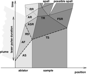
In the simulations, the surface of the plastic was heated to plasma conditions rapidly after the start of the laser pulse. The plasma then absorbed the incident laser energy, forming a nearly steady state plume close to the plastic. The plasma pressure and reaction to plasma flow induced an elevated pressure in the remaining condensed-phase plastic, driving a shock wave. As was found previously Swift_elements_04 ; Swift_alloys_04 , a laser pulse of constant irradiance did not induce a constant driving pressure in the condensed region. Instead, there was an initial spike of pressure tens of percent higher, decaying rapidly to a more constant sustained pressure. This sustained pressure typically decreased by a few percent during the laser pulse. The EOS used exhibited simple, concave behavior, so the decaying pressure in the spike and the plateau was able to catch up and erode the higher pressure states ahead, reducing the shock pressure monotonically as it propagated through the material.111In an optimized shock-loading experiment, the pulse shape of the laser is adjusted to induce a more constant pressure history. Constant irradiance histories are considered here for simplicity. After the end of the pulse, the ablation pressure fell rapidly, and a rarefaction wave propagated into the shocked material, releasing the pressure. For the thickness and pulse duration chosen, and over the irradiance range considered, the shock reached the rear surface of the plastic before the rarefaction caught up, so a second rarefaction wave from the rear surface also propagated into the material. (Fig. 1)

Temperatures in the ablation plume were predicted to be of order 10-100 eV. The mass density and time scales were low enough that conductive heating of the condensed-phase ablator was not significant. (Fig. 2)

The relationship between irradiance and ablation pressure was investigated by performing simulations with the same 10 ns laser pulse duration, and varying the irradiance between 0.1 and 100 PW/m2.222Irradiances are commonly expressed in the non-SI unit of GW/cm2; 1 PW/m2=100 GW/cm2. The sustained pressure following the initial peak was represented well by a power law in irradiance :
| (7) |
The fitting uncertainty in the parameters is 1.5%, and the uncertainty in the irradiance-pressure values is around 5%, because of temporal variations in the pressure. This result is consistent with previous studies on elemental metals Swift_elements_04 , though the exponent here is larger, and the irradiance-pressure relation is better reproduced by the power law fit despite covering a wider range of irradiance. The exponent is consistent with experimental and calculational results obtained for polystyrene Grun81 , and the prefactor is similar to the value implied by these results. The exponent is also consistent with more recent simulation results for parylene Colvin05 .
In this regime of irradiance, laser and thermal radiation penetrates the material much more slowly than the shock wave passes through, so there is a region of compressed material heated only by the passage of the shock between the ablation surface and the undisturbed material ahead of the shock. It is important to know the rate at which material is ablated, to ensure that the ablator is thick enough for a laser pulse of given irradiance and duration. The ablation rate was extracted from the simulations by observing the time of first outward motion of points in the material. For convenience in choosing a thickness of ablator, a Lagrangian ablation rate was calculated, i.e. with respect to the original position of the material. The ablation-supported shock compresses material before it is ablated, so the ablation rate, with respect to the instantaneously compressed material, is lower than the Lagrangian rate. For laser irradiances from 0.1 and 10 PW/m2, the ablation rates were fitted well by a straight line, indicating that a constant irradiance produces a constant ablation rate. At an irradiance of 100 PW/m2, the ablation rate decreased significantly over the 10 ns of the laser pulse. Ablation was predicted to continue at a similar rate for around 20% of the duration of the laser pulse after its end, because of retained heat in the ablation plume. After this time, the ablation rate decreased rapidly (Fig. 3). The individual ablation rates were reproduced accurately by the relation
| (8) |
valid for between 0.1 and 100 PW/m2. Above 10 PW/m2, this relation ceases to be valid over the full 10 ns investigated: at 100 PW/m2 it is valid for the first 1 ns. The fitting uncertainty in the parameters is 0.5%. Note that 1 km/s=1 m/ns. This result is similar to the results reported for the ablation of polystyrene Grun81 , though our simulations predict a larger prefactor. In the previous results, the depth of material ablated was inferred indirectly from measurements of the ablation plasma. 333In the previous work Grun81 , ‘ablation velocity’ referred to the speed of the expanding plasma, and not to the speed of the ablation front through the compressed ablator.

There is significant uncertainty in the EOS of matter, particularly in the warm dense matter regime of the ablation plume. The uncertainty is correspondingly greater for a material for which no specific EOS has been developed, as discussed above. It was found previously Swift_elements_04 ; Swift_alloys_04 that pressures induced in the condensed region were fairly insensitive to the details of the plasma EOS. The sensitivity was investigated here by performing equivalent sets of simulations using the EOS and opacity for parylene-C from the SESAME library: (tables 7771 and 17620) Johnson-Lyon91 , and also polystyrene (tables 7590 and 17593) Barnes-Lindstrom76 . The two parylene models gave the same ablation pressure to within 1-2%, and the shock speeds were almost identical. The polystyrene model gave a smaller initial pressure spike and a sustained pressure that was up to several percent lower, but with less of a decrease over the pulse duration and hence a slower decay as it propagated through the plastic. The shock speed in polystyrene was significantly different: slower at low pressures and faster at high pressures. These variations are all small compared with typical uncertainties in mean irradiance in laser ablation experiments. (Fig. 4.)
The sensitivity to ablator material was investigated further by performing equivalent simulations for polyethene (tables 7171 and 17171) Dowell82 . The ablation pressures were 5-10% lower than for parylene-D, but within 5% of polystyrene. The pressure profile was generally similar to that of polystyrene. (Fig. 4.)

For x-ray diffraction experiments, the timing of the x-ray pulse with respect to the shock-loading of the sample is particularly important. The effect of composition and EOS was significantly more sensitive than the ablation pressure (Fig. 5).

Experimentally, it has been found that some laser light may be transmitted through the plastic coating before the opaque plasma sheath forms, inducing earlier ablation of the sample material behind by a small amount of the laser energy. This early transmission was not predicted in the radiation hydrodynamics simulations, which (as is common) did not include an adequate model of the line opacity and breakdown of the plastic. A palliative is to deposit a thin, metal flashing on the surface of the plastic to prevent early transmission. A typical flashing is 100 nm of Al, though other metals have been used Delettrez90 . The Al layer potentially has an effect on the ablation pressure, apart from the palliative effect. This effect was predicted by performing simulations in which the first 100 nm of the plastic was replaced by Al. At 0.1 PW/m2, the presence of the Al increased the sustained ablation pressure by 10-15% and made it more constant, but introduced slight wave reverberations in the compressed ablator (Fig. 6). The difference was smaller at 1 PW/m2, and negligible at 10 PW/m2 and above.

There is also a potential effect from x-ray preheating of the sample, induced by K-shell radiation from the ablator or flashing. X-ray preheating is very sensitive to intensity variations in the laser beam, as x-ray yield is highly non-linear in laser irradiance Workman01 . The fluence of preheating x-rays is therefore very sensitive to the beam quality of the specific laser system, including any phase plate used to reduce large-scale intensity variations. The degree of x-ray heating also depends on the opacity of the sample material. Experimental evidence and theoretical predictions for x-ray preheating in such experiments is mixed: simulations have indicated that preheating may be significant in our regime of interest Colvin05 , but whereas experiments have shown little or no preheating Grun81 ; Swift_elements_04 ; Swift_alloys_04 ; Peralta05 . While preheating is a potential concern when the initial temperature of the sample is important, it has a much smaller effect on wave interactions caused by the presence of the ablator, so we do not consider it further in the present work.
At the end of the laser pulse, the pressure at the ablation surface drops rapidly as the ablation plume expands and cools. Until two-dimensional expansion takes effect, the pressure gradient in the ablation plume is inversely proportional to the pulse length, so the rate at which the pressure falls is inversely proportional to the pulse length.
IV Laser pulse shaping for constant ablation pressure
The ablation pressure can be made constant in time by adjusting the temporal shape of the laser pulse. Many, though not all, large laser systems allow the power history to be controlled, so a desired temporal shape can be delivered to some finite level of precision. On lasers with large numbers of beams but a simple shape from each (such as a constant power), a smooth temporal shape can be approximated by altering the energy and relative timing of the beams.
The principle of pulse shaping for constant ablation pressure was demonstrated for parylene-N ablators by performing simulations in which the laser irradiance was adjusted. These simulations were performed for a laser pulse where the time-dependent irradiance was represented in tabular form, with table entries at the start and end of the pulse of equal value for a constant irradiance. The procedure followed was first to adjust the irradiance at the end of the pulse, giving a linear ramp starting at the initial irradiance, and then to add extra points between the first and last and change their values to remove shorter time scale variations in pressure. The sustained ablation pressure was made constant by ramping the irradiance up in time, and the initial pressure spike was removed by reducing the irradiance early in time and following a more gentle approach to the main part of the pulse. This procedure was demonstrated previously for direct ablation of Be Luo05 . Calculationally, it was possible to make the induced pressure constant to any desired precision by adjusting the laser irradiance history (Fig. 7). For irradiances from 0.1 to 10 PW/m2, the ramp was 10-30% of the mean irradiance.

V Wave interactions with the sample
When the ablator is in contact with a sample, the impedance mismatch between the ablator and the sample lead to wave interactions which change the pressure history in the ablator and may lead to multiple waves in the sample. In most cases of interest, the sample has a higher shock impedance than the plastic ablator, so the ablation-induced shock reflects a shock from the interface between the ablator and the sample.
In this discussion of wave interactions, we consider a simplified situation where the laser irradiance history has been adjusted to give a constant drive pressure in the ablator, which will induce a constant initial shock pressure in the sample. Early in the laser pulse, an ablation-driven shock is induced, driving a transmitted shock in the sample and a reflected shock in the ablator. If the laser pulse is long enough, when the reflected shock reaches the ablation surface, double-shocked ablator material is then ablated, resulting in an ablation pressure that is slightly higher than before, but generally lower than the double-shocked pressure. The resulting ablation surface release wave propagates through the ablator and is transmitted into the sample, reflecting a further weak release wave back through the ablator. When the transmitted shock reaches the free surface of the sample, a release wave propagates backward into the sample. When the laser pulse ends, a strong release wave propagates through any remaining ablator and forward into the sample. Where the strong release waves interact, the sample material is subjected to tension, and spall may occur. (Figs 8 and 9.)

The impedance mismatch between most metals and plastics such as parylene and polyethene means that a given ablation pressure in the plastic induces a considerably higher pressure in a metal sample. The pressure enhancement was estimated for the plastic EOS used above and published EOS for Al and Cu, by finding the intersection between the secondary shock Hugoniot for a given initial shock state in the plastic and the principal Hugoniot in the metal in pressure-particle speed space. The EOS of Al was as above; that for Cu was SESAME table 3330. Shock Hugoniots and their intersections were found numerically Swift_genhug07 . Repeating this procedure for a range of ablation shock pressures, relations were found between the pressure in the plastic and the pressure in the metal (Fig. 10).

Radiation hydrodynamics simulations were performed to predict the integrated effect of ablative loading via a plastic ablator on the loading history experienced by the sample. As for the ablator-only simulations, a geometrically expanding spatial discretization was used. The sample was chosen to be 25 m thick. Simulations were performed for ablators 10 and 20 m thick, with Al flashing. The laser pulse was taken to be 3 ns long, with constant irradiance, which are specifications often used for material dynamics experiments at the Janus laser Hawreliak06 . With a laser pulse of constant irradiance, the pressure was predicted to decrease with time during the pulse, though the compression varied less. Simulations were performed for irradiances of 5, 10, 20, and 50 PW/m2. The peak pressure in the sample was in agreement with the impedance mismatch calculations, and decayed as the shock propagated through the sample. With a thicker ablator, the pressure in the sample was more constant. (Figs 11 to 13.)


For comparison, simulations of ablative loading of uncoated samples were performed. For a given irradiance, the pressure induced in the sample was significantly lower when ablated directly, though the duration of the period of high pressure was greater. Ablation of plastic was predicted to generate a slightly lower pressure than ablation of the metal sample, but the large impedance mismatch more than compensated for the reduced ablation pressure. With an ablator, the pressure fell more slowly at the end of the laser pulse. With an ablator, the pressure varied less during the initial shock, with a constant laser irradiance. The inclusion of the low density ablator increased the coupling of laser energy to the sample. (Figs 14 and 15.)


One way to think of the function of the ablator is that it converts laser energy into kinetic and potential energy in the moving, compressed ablator, which is then partly transferred to the sample. For a given irradiance, laser pulse length, and sample material, there is an optimum thickness for any ablator to maximize the duration of the peak shock pressure applied to the sample. The optimum thickness is such that the laser pulse ends when the reflected shock reaches the ablation surface. When the ablation rate is a constant in time, this relationship can usefully be expressed as an effective speed: microns of ablator per nanoseconds of laser pulse; this is a useful quantity when designing ablation experiments. The optimum relationship between thickness and pulse length depends on the sample material too, because the impedance mismatch affects the pressure of the reflected shock and therefore its transit time. It should be emphasized that this ‘ablator drive speed’ does not represent any individual physical wave speed: it is a composite of the initial ablator shock speed, the speed of the reflected shock through the pre-compressed ablator, and the ablation rate. If the laser pulse is the optimum length for the ablator thickness, or longer, then the duration of the higher pressure drive experienced by the sample at the interface with the ablator can be related to the duration of the laser pulse, as a load duration factor. If the laser pulse is longer than the optimum for a given ablator thickness, the principal pressure pulse applied to the sample does not become longer, but the sample pressure releases to the ablation pressure, and this lower pressure is sustained for longer. There is a minimum laser pulse duration for the peak pressure to reach the sample. If the laser pulse is longer than this, but shorter than the ablator thickness optimum, the duration of the pressure pulse at the sample varies proportionately from zero to the maximum.
The initial mass density of the ablator is . The ablation-driven shock travels at a speed and compresses the ablator to a mass density , ablating material at a rate with respect to the uncompressed ablator (the quantity calculated above) or of the compressed ablator. The shock reflected from the sample back through the ablator travels at a speed and compresses the ablator further to a mass density . In this state, the speed of sound is : this is the speed of the head of the ablation surface rarefaction. For an ablator of initial, uncompressed thickness , the transit time of the initial ablation shock is : this is the time that loading starts in the sample after the start of the laser pulse. The transit time of the reflected shock is
| (9) |
The optimum laser pulse length is , so the ablator drive speed is
| (10) |
The residual thickness of ablator when the reflected shock reaches the ablation surface is
| (11) |
so the transit time of the ablation surface release is
| (12) |
The time for which the initial pressure is applied to the sample is thus
| (13) |
so the load duration factor is
| (14) |
If the sound speed in the ablation shocked state is , traveling through the compressed ablator, the minimum pulse length for the peak pressure to reach the sample can be found by calculating the point in the ablator at which the head of a release wave at the end of the laser pulse would catch up with the ablation shock. The minimum time is proportional to the sample thickness, so an effective ‘catch-up speed’ can be defined for a given ablation pressure:
| (15) |
where , , and are all in the principal Hugoniot state for the ablator at the ablation pressure. For a given laser pulse duration , the maximum depth in the ablator before the ablation shock starts to decay is then . This calculation can also be used to calculate the maximum sample thickness for a supported shock in experiments where the sample itself is ablated Swift_maxthick_01 . For an ablator of given thickness , the minimum laser pulse duration . For laser pulse durations between this and , the duration of the peak pressure pulse applied to the sample is
| (16) |
As a planar loading or unloading wave propagates through a sample, release waves from the edge will usually erode the shocked region.444The exception is if ‘edge faking’ using an angled boundary with a material of higher shock impedance is present to give a perfect impedance match, which is difficult in general, and may reflect a shock or release if not designed correctly. The head of the release wave initiated by any lateral variation in the material or loading conditions is an expanding circle with respect to the shocked material (Fig. 16): a cylinder or torus in two-dimensional plane or axisymmetric geometry respectively. The lateral variation in a projectile impact experiment is the edge of the projectile on the impact surface; for laser ablation it is the edge of the focal spot – though unlike a projectile impact, the pressure does not release to zero because the ablation of laterally-released material may induce a pressure almost as high as that from the shock-compressed ablator. The speed of sound in the shocked region is greater than the shock speed, so the release wave erodes the shock. The hydrodynamic flow is self-similar, so the erosion of the shock by the release wave can be characterized by the angle at which the planar region of the shock is eroded. is often assumed to be , but this is not generally the case. As with the catch-up speed, these angles can be calculated given the sound speed on the principal Hugoniot , by considering the propagation of a disturbance from the edge of the planar shock region, traveling at , across material moving with the particle speed parallel with the shock, and the resulting speed of the disturbance as it moves across successive positions of the shock itself:
| (17) | |||||
| (18) |
An equivalent analysis has been used previously to measure the sound speed on the Hugoniot Zeldovich66 . For a circular laser spot of diameter , the diameter of the region of the sample initially subjected to the maximum shock pressure is
| (19) |
where is the thickness of the ablator. Subsequent release depends also on the sound and particle speed in the double-shocked ablator material. The same analysis, using the Hugoniot state in the sample, can be used to predict the lateral erosion of the shock in the sample itself. The edge release angle is important when designing experiments to study phenomena at the leading edge of the shock. For experiments on release from the shocked state, including tensile damage, an important design parameter is the scale rate at which lateral release propagates radially through the shocked material, .555The ratio may be greater or less than one. A steady shock is always subsonic with respect to the flow behind. However, with respect to the shocked material, the shock moves at , which does not exclude .

The ablator drive speed, load duration factor, catch-up speed, edge angle, and lateral release ratio were calculated using a generalized shock dynamics algorithm to determine the principal and secondary Hugoniot states Swift_genhug07 , using the same EOS as above (Figs 17 to 20). As was found previously for direct ablation of metals Swift_maxthick_01 , the catch-up speed exhibited a minimum value around the bulk modulus of the ablated material: at the minimum, the ablator thickness should be smallest for a given laser pulse duration. The ratio was greater than 3 for all relevant pressures, and rose past 10 for ablation pressures above 40 GPa: lateral release in the ablator may be a concern in experiments with thick ablators, though the pressure may not drop rapidly once release starts as it is sustained by the ablation. Radiation hydrodynamics simulations were performed of the integrated system, with consistent results for the duration of the peak shock state in the sample. It should be noted that these quantities depend on material properties in states significantly off the principal shock Hugoniot of the ablator. The hydrodynamic relations above are valid so long as radiation and charged particle transport are not significant within the compressed ablator or the sample. The radiation hydrodynamics simulations indicated that radiation transport is unlikely to be significant in this regime; they did not include electron transport. For ablatively driven experiments on a range of materials at a range of shock states, a wide range of off-Hugoniot states may be involved. These properties are often not known at all accurately from experimental measurements. It would be more efficient to use experimental measurements to validate and adjust wide-ranging theoretical models, rather than attempting to measure the properties of the ablator so generally. Experiments should include the principal Hugoniot of the ablator, and also off-Hugoniot states induced by, for example, reflected shocks from high-density samples. These data could be acquired using laser loading experiments with velocimetry measurements. Transparent samples would allow the velocity history to be measured at the interface. Whether transparent or opaque, the samples should be thick enough to prevent release waves from their free surface from perturbing the states inside the ablator, which would complicate the experiments. Measurements would include the amplitude and duration of the shock in the sample.


VI Conclusions
The sensitivity of ablation pressure in CH-based plastic ablators to uncertainties in equation of state or composition was predicted to be 5-10%, which is small compared with typical uncertainties in laser irradiance. A laser pulse of constant irradiance was predicted to induce an ablation pressure that decreased by several percent per nanosecond, but was significantly more constant than the pressure history induced by direct ablation of metal samples. A simple relationship between laser irradiance and shock pressure was deduced from the simulations, valid for irradiances from 0.1-100 PW/m2. Al flashing, used to prevent early-time shine-through, was predicted to make at most a few percent difference in loading history once dielectric breakdown had occurred, increasing the pressure and flattening the pressure history at lower irradiances. It was demonstrated that the irradiance history can be adjusted to produce a more constant pressure history.
The impedance mismatch between plastic ablators and metal samples induces a stronger transmitted shock in the sample, by a factor of around 1.8 for Al and 2.5 for Cu. The shock reflected into the ablator interacts with the ablation surface to produce a stepped pressure history in the sample, the pressure reducing to closer to the ablation pressure. This composite loading history should be taken into account when designing and interpreting material dynamics experiments. The shock pressure is applied to the sample for a significantly shorter time than the laser pulse duration, because the successive waves in the ablator are faster than the initial ablation-driven shock.
A compact method was found for representing the optimum ablator thickness for a given laser pulse duration (or vice versa), as an effective speed. A similar method was found to represent the relationship between the laser pulse duration and the duration of the initial, peak pressure pulse applied to the sample. These relations are helpful in the design and interpretation of ablatively driven shock experiments.
Acknowledgments
We would like to acknowledge the contributions of Jeff Colvin for comments and advice on radiation hydrodynamics simulations and the manuscript, David Young for providing the equation of state and comments for parylene-N, and Jon Larson for advice on HYADES simulations, and Flavien Lambert for comments on the manuscript. This work was performed in support of Laboratory-Directed Research and Development project 06-SI-004 (Principal Investigator: Hector Lorenzana), under the auspices of the U.S. Department of Energy under contracts W-7405-ENG-48 and DE-AC52-07NA27344.
References
- (1) D.C. Swift, T.E. Tierney IV, R.A. Kopp, and J.T. Gammel, Phys. Rev. E 69, 036406 (2004).
- (2) D.C. Swift, J.T. Gammel, and S.M. Clegg, Phys. Rev. E 69, 056401 (2004).
- (3) D.C. Swift and R.P. Johnson, Phys. Rev. E 71, 066401 (2005).
- (4) B.A. Remington, P. Allen, E.M. Bringa, J. Hawreliak, D. Ho, K.T. Lorenz, H. Lorenzana, J.M. McNaney, M.A. Meyers, S.W. Pollaine, K. Rosolankova, B. Sadik, M.S. Schneider, D. Swift, J. Wark, and B. Yaakobi, Mat. Sci. and Tech. 22, 4 (2006).
- (5) P. Peralta, D. Swift, E. Loomis, C.H. Lim, and K.J. McClellan, Met. and Mat. Trans. A 36, 6, 1459-1469 (2005).
- (6) C.F. Powell, J.H. Oxley, and J.M. Blocher Jr, “Vapor Deposition” (Wiley, New York, 1966).
- (7) D.M. Mattox, “Handbook of Physical Vapor Deposition (PVD) Processing” (Noyes, Bracknell, 1998).
- (8) J. Grun, R. Decoste, B.H. Ripin, and J. Gardner, Appl. Phys. Lett. 39, 7, pp 545-547 (1981).
- (9) J. Delettrez, D.K. Bradley, P.A. Jaanimagi, and C.P. Verdon, Phys. Rev. A 41, 10, 5583-5593 (1990).
- (10) J.D. Colvin and D.H. Kalantar, in M.D. Furnish, M. Elert, T.P. Russell, and C.T. White (Eds) Proc. American Physical Society Topical Conference on Shock Compression of Condensed Matter, held Baltimore, MD, 31 July - 5 August 2005, CP845 (American Institute of Physics, New York, 2006).
- (11) J. Hawreliak, J.D. Colvin, J.H. Eggert, D.H. Kalantar, H.E. Lorenzana, J.S. Stölken, H.M. Davies, T.C. Germann, B.L. Holian, K. Kadau, P.S. Lomdahl, A. Higginbotham, K. Rosolankova, J. Sheppard, and J.S. Wark, Phys. Rev. B 74, 184107 (2006).
- (12) D. Mihalas and B.W. Mihalas, “Foundations of Radiation Hydrodynamics” (Oxford, New York, 1984).
- (13) G.B. Zimmermann and W.L. Kruer, Comments Plas. Phys. 2 2, 51 (1975).
- (14) Documentation for HYADES computer program, version 01.05.11 (Cascade Applied Sciences Inc, Golden, Colorado, 1998).
- (15) R. Dendy, Plasma Physics, (Cambridge University Press, Cambridge, 1993).
- (16) K.S. Holian (Ed.), Los Alamos National Laboratory report LA-10160-MS (1984).
- (17) Ya.B. Zel’dovich and Yu.P. Raizer, Physics of shock waves and high temperature hydrodynamic phenomena, (Academic Press, New York, 1966).
- (18) D.A. Young (Lawrence Livermore National Laboratory), private communication, 2007.
- (19) S.D. Rothman, A.M. Evans, C.J. Horsfield, P. Graham, and B.R. Thomas, Phys. Plasmas 9, 5, pp 1721-1733 (2002).
- (20) J.D. Johnson and S. Lyon, unpublished.
- (21) J. Barnes and A. Lindstrom, unpublished.
- (22) F. Dowell, Los Alamos National Laboratory report no. LA-9564-MS (1982), unpublished.
- (23) J. Workman and G.A. Kyrala, Rev. Sci. Instrum. 72, 1, pp 678-681 (2001).
- (24) S.-N. Luo and D.C. Swift, Los Alamos National Laboratory report no. LA-UR-05-2575 (2005), unpublished.
- (25) D.C. Swift and J.G. Niemczura, Los Alamos National Laboratory report no. LA-UR-01-4541 (2001), unpublished.
- (26) D.C. Swift, Numerical solution of shock and ramp loading relations for general material properties, preprint arXiv:0704.0008.