Combined macro- and micro-rheometer for use with Langmuir monolayers
Abstract
A Langmuir monolayer trough that is equipped for simultaneous microrheology and standard rheology measurements has been constructed. The central elements are the trough itself with a full range of optical tools accessing the air-water interface from below the trough and a portable knife-edge torsion pendulum that can access the interface from above. The ability to simultaneously measure the mechanical response of Langmuir monolayers on very different length scales is an important step for our understanding of the mechanical response of two-dimensional viscoelastic networks.
pacs:
83.60.Df,68.08.-p,82.35.Pq 82.70.Gg,Soft-matter systems play critical roles both in technological applications and in biology. Most examples of soft matter are complex fluids, exhibiting both solid- and fluid-like responses. One of the challenges in soft-matter research is the quantitative understanding of such behavior. Complex dynamics are typically the result of complex structure spanning a range of length scales. Often, the large-scale response of the system depends in a non-trivial fashion on the interaction between mesoscopic structures in the system. The local response within one of these mesoscopic structures can be very different from the macroscopic response. For example, aqueous foam is composed of gas bubbles separated by liquid films. Measurements within a liquid film suggest the material is fluid. However, for applied stress below the yield stress, the macroscopic foam acts as a solid. Due to various additives, the liquid film itself may be viscoelastic, and the details of this “microscopic” response can, in turn, directly impact the details of the macroscopic behavior.
A system of great biological interest, for which length scales play an important role are semi-flexible polymer networks. Many structures in biology are composed of semi-flexible networks of protein filaments, such as the actin cytoskeleton, that are also connected with lipid membranes. The need to understand both the microscopic and macroscopic response of such a composite system provided much of the motivation for the apparatus we report on in this paper. The other motivation was the need to make measurements on a robust model system. For this, we have chosen to focus on Langmuir monolayers as a model for the lipid structures. Langmuir monolayers are single-molecule-thick layers of amphiphilic molecules at the air-water interface, and thereby resemble a half of a lipid bilayer which forms cell membranes. There exists a well-developed set of tools for studying their mechanical properties. This offers many advantages when pursuing mechanical studies, and it allows us to build on existing technology.
One can categorize the existing methods for measuring the viscoelastic properties of Langmuir monolayers according to the length scale probed by the technique. The more common techniques that probe the system on relatively large length scales include needle viscometers BFFR99 , channel viscometers HK38 ; CHB42 ; SYZ93 ; SKB94 , the knife-edge torsion pendulum MS70 ; FMA92 ; AMXK83 ; KSMBS94 ; GKMD97 , and light-scattering HL76 ; L81 . Our group has also developed a Couette-style rheometer that expands on standard knife-edge torsion pendulum techniques GD98 .
The first use of microscopic-scale local techniques in Langmuir monolayers was based on measuring relations between translational and rotational mobilities of particles diffusing in the monolayer HPWS82 ; SD75 . In this regard, a useful feature of Langmuir monolayers is their rich phase behavior, with the equivalent of gas, liquid, liquid crystal (often referred to as liquid condensed), and crystalline phases. Because they often exhibit phase coexistence, the domains of one phase can be used as the ‘particles” to probe the properties of the other phase. For example, experiments have included measuring the diffusion of liquid crystalline domains KM93 , and using liquid crystalline domains as particles for measuring velocity profiles SKB94 . More recently, Brewster-angle microscopy has been used to study the motion of the domains S01 ; IIS01 . Our apparatus uses microrheological techniques that rely on the introduction of tracer particles. It is based on similar techniques discussed in Ref. Fischer:00 ; Fischer:01a ; Fischer:01b ; Rondelez:03 . However, as discussed in more detail later, we expand on these techniques in several ways.
In considering the design of an apparatus that can measure rheological properties on multiple length scales, we decided to pursue a modular design that combines two established rheological techniques: particle microrheology and the knife-edge torsion pendulum. Both of these measure the complex shear modulus, . In linear response, the complex shear modulus provides the connection between an oscillatory strain and stress as a function of the oscillation frequency through the relation: . The real part of is the elastic modulus and the imaginary part is related to the viscous response (i.e. energy dissipation in the system). The difference between the microrheology measurements and the knife-edge torsion pendulum is in the length scales being probed. Typically, microrheology uses micron-size beads embedded in the material and the torsion pendulum is on the order of mm to cm. We will briefly review each technique and discuss the design goals for each of these. Then, we will describe our apparatus in detail.
The most basic form of microrheology uses position fluctuations of tracer particles (typically micron sized spheres) embedded in the material as a probe Schmidt:97 ; SchmidtPRL:97 ; Schmidt:99 . The displacement of a single spherical probe is described by the standard Stokes-Einstein relationSchmidtPRL:97 ; Levine:00 :
where is the complex shear modulus.
This method is termed passive microrheology because only the thermal force fluctuations experienced by the particles are used as the driving force. Our system is based on a procedure for determining the shear moduli that is fully discussed in Schnurr et al Schmidt:97 . Essentially, one uses the fluctuation-dissipation theorem to relate the power spectral density of the thermal motion of the bead to the imaginary part of the complex response function . When measuring over a large enough frequency space, a Kramers-Kronig integral can be used to recover the real part of the response function , and the total complex response function is then related to the complex shear modulus by the generalized Stokes-Einstein relation (GSER):
.
Therefore, a critical design element in the system is the ability to measure over a wide range of frequencies. This will be discussed in the detailed description of the apparatus. The final key experimental component for the microrheology is the use of optical tweezers to trap the probe particle Chu:86 .
The knife-edge torsion pendulum method is well established to probe viscoelastic properties of surface layers on air-water interfaces. Essentially, one suspends a Teflon disk with a knife-edge at its circumference in the monolayer. The disk is driven with a known applied torque, which corresponds to an applied stress for the monolayer. The angular response of the disk corresponds to the strain response of the monolayer. One must correctly account for the contribution of the fluid-subphase, and the details of this are given in Ref. GKMD97 . The key elements in this case are the driving mechanism and the measurement of the rotation angle. For the application discussed here, it was necessary to adopt a design that could be easily integrated with the microrheology technique.
To achieve the integration of the knife-edge torsion pendulum with the microrheology technique required the design of a new Langmuir monolayer trough with full optical access from below and the adaptation of our existing knife-edge torsion pendulum. Access from below was necessary for the optical tweezers and particle tracking in order to harness the full power of microrheology. In addition, for added flexibility, we provided access from below for a fluorescence microscope so as to leave space above the monolayer for the knife-edge torsion pendulum. The main mechanical adaptation necessary for the knife-edge torsion pendulum was the design of a modular unit that can function as a stand-alone device. This makes it possible to remove the device for the use of additional tools in combination with the optical tweezers. It has the added benefit that the knife-edge torsion pendulum can be used and calibrated in a separate mini-Couette rheometer. We will first describe the Langmuir trough and integrated microrheology apparatus and then we will separately discuss the design of the stand-alone knife-edge torsion pendulum. The combination of the two techniques into one instrument creates a powerful, high-precision instrument capable of exploring mechanical properties of surface films that were previously not accessible.
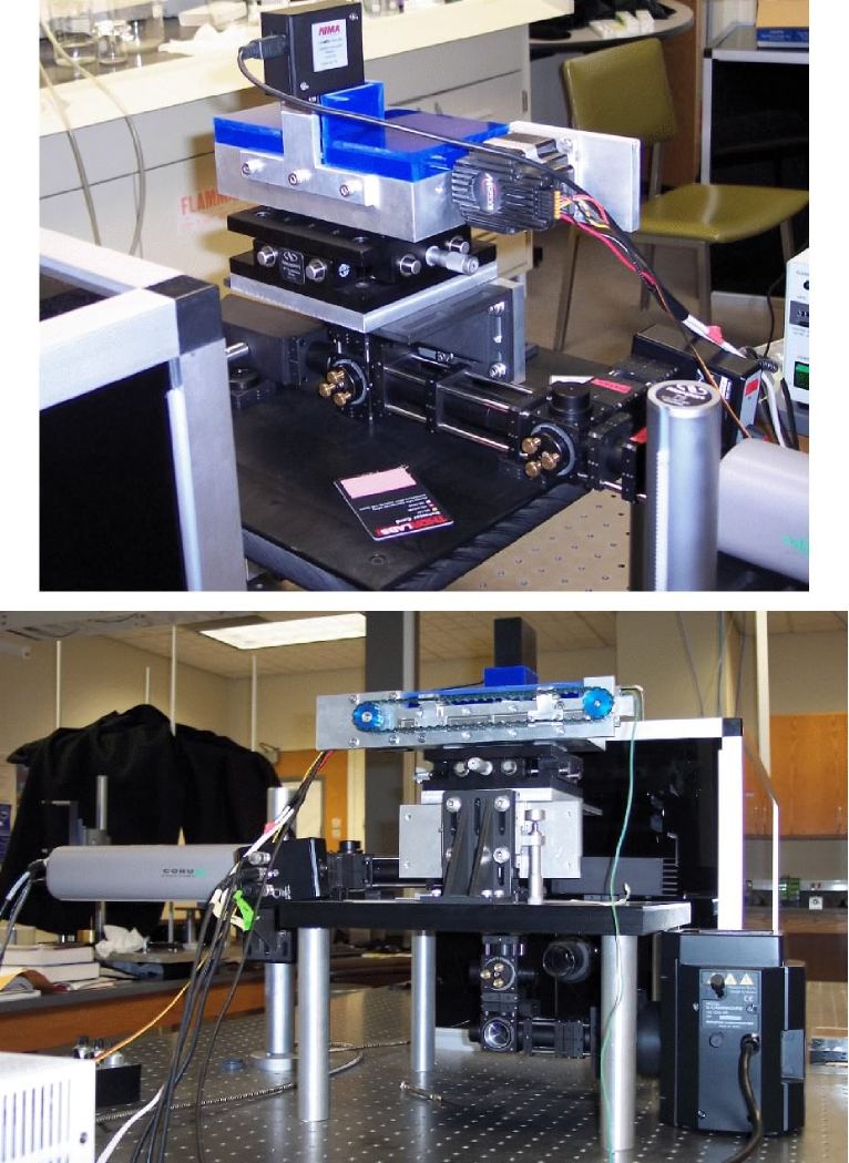
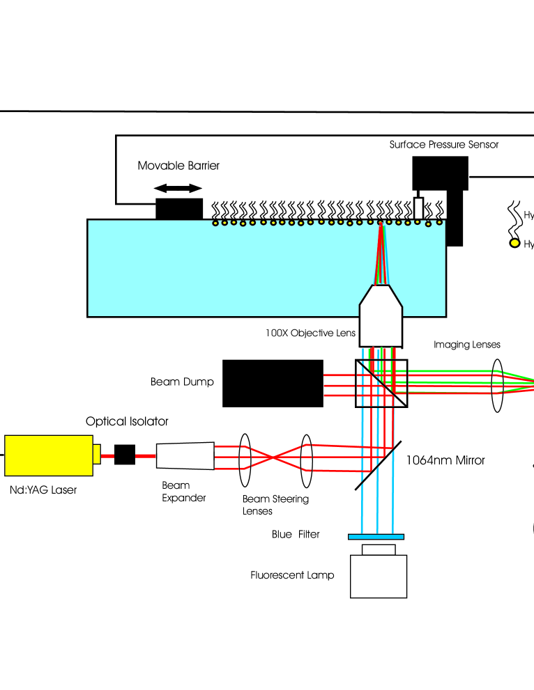
The integrated Langmuir trough consists of three optical instruments and a surface tensiometer. Figure 1 provides two view of the apparatus, and Fig. 2 is a schematic of the overall apparatus. Details of each portion of the apparatus are provided in the following sections. The integration of these systems into one master instrument allows us to simultaneously image and mechanically manipulate surface films in the Langmuir trough and track embedded particles. A number of the components are standard equipment for Langmuir monolayer troughs. For example, a commercial surface pressure sensor SurfacePressureSensor is used to characterize the phase of the monolayer. A typical isotherm is illustrated in Fig. 3 for a DPPC monolayer.

Due to space and cost constraints, we have chosen to use a custom built fluorescence microscope that images the monolayer from below instead of mounting the system on a full commercial fluorescence microscopic (see Fig. 4). Fluorescence microscopy is essential to be able to specifically detect molecules at the interface that can not be detected using standard bright-field microscopy. Selected populations of molecules in the sample (in our case lipids and/or actin) are modified by chemically attaching a fluorophore.
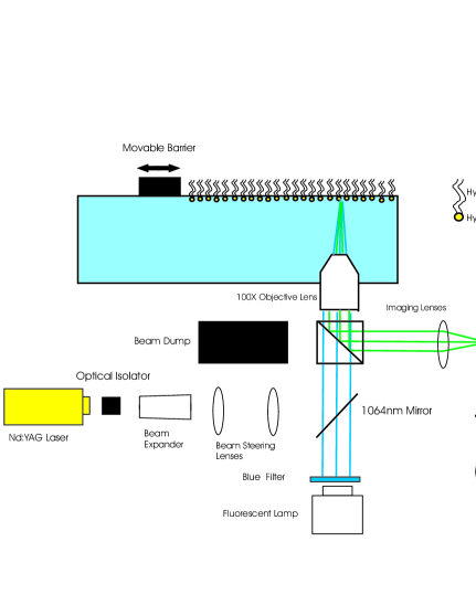
In our optical configuration, we use a mercury arc lamp Lamp combined with appropriate excitation filters mounted in a filter wheel, to excite fluorescence, and the corresponding emission filters on a filter wheel connected to our intensified CCD camera CCDCamera to detect fluorescence. This configuration allows us to use different fluorophores during our experiments and thus allows us to selectively image different components of our sample. The 2 filter cubes we have currently installed are the FTIC and rhodamine filters. One particularly useful application of this capability is to use one fluorophore for the lipid monolayer (such as Bodipy) and to use another fluorophore for proteins introduced into the subphase (such as rhodamine actin).
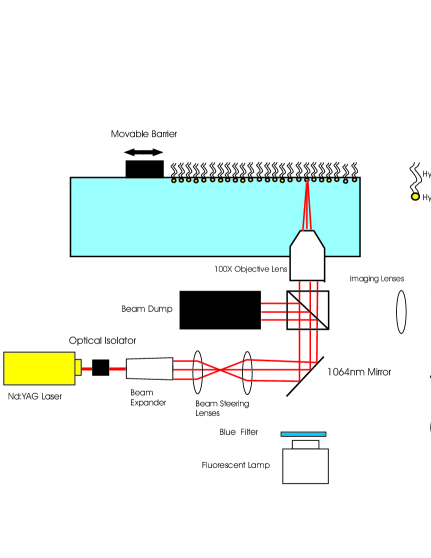
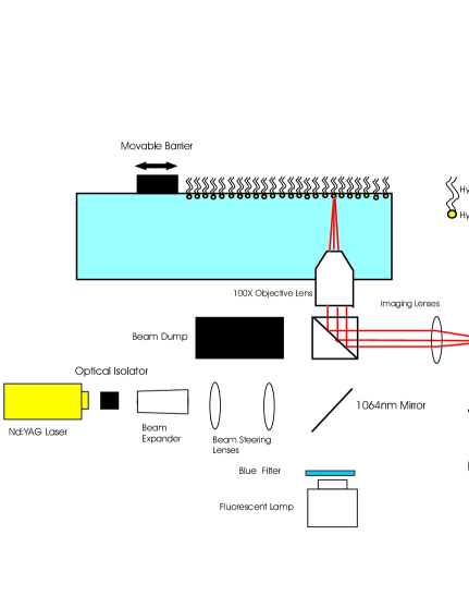
The basic principle of an optical tweezer is to focus a reasonably high-powered laser to a diffraction limited focus. The light intensity gradient creates a force on objects of a higher index of refraction than the surroundings. The two basic components of an optical tweezers are thus a laser Laser and an objective lens ObjectiveLens (see Fig. 5). The objective lens should have a high numerical aperture to create a steep enough intensity gradient LANG03 . The water immersion objective lens we use for our optical tweezer system has a numerical aperture of 1.0 and a working distance of 1.5 mm.
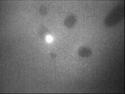
Additional optical components were added to the laser/objective lens system in order to control trap strength and to allow us to steer the trap location in the sample. An optical isolator prevents backscattering which can cause laser instability. A beam expander increases the beam diameter 4-fold in order to use the maximal numerical aperture by filling the back aperture of the objective lens. Two 100 mm focal length lenses form a telescope for beam steering. The first lens is mounted to an 3-axis translation stage. Translation of this lens steers the trap location in 3 dimensions within a range of several microns in each axis. An example of an image of a particle in the trap (using the Fluorescence microscope) is shown in Fig. 6
A key element of the microrheology system is the particle displacement measurement. The thermal position fluctuations are close to and beyond the limits of the spatial optical resolution that can be achieved with standard video particle tracking. In addition, the frame rate of the CCD camera used for fluorescence microscopy is limited to a range of 10-100 Hz. This imposes a limit on the range of frequencies over which the complex shear modulus can be determined by video particle tracking. Using the quadrant diode based displacement detection system described in the next section (see Fig. 7), we can probe the frequency response of the system up to 100 kHz.
The back-scattered laser light from the trapped particle is imaged onto a quadrant photodiode in a method similar to Helfer et al Chatenay:00 . When forward-scattered light can be collected, one can use back-focal plane interferometry Allersma:98 ; Schmidt98. In our case, we have no optical access from above and therefore use backscattered light. The detection optics consists of a beam splitter, imaging lenses, a degree 1064 nm laser line mirror, and a quadrant photodiode QuadrantPhotodiode . The beam splitter is used to reflect some of the back-scattered laser light from the trapped particles into the imaging optics. The lenses are positioned to form an image of the particle on the quadrant photodiode with a final magnification of 100X. The laser line mirror is used both as a filter to prevent any visible light from the fluorescence imaging from reaching the quadrant photodiode and to center the back-scattered light onto the quadrant photodiode. In addition, the laser line mirror protects the CCD camera from being damaged by the backscattered laser light. The quadrant photodiode then records the position of the particle with high spatial and temporal resolution in terms of the four output photo-currents. The sampling frequency is typically 66 kHz and the number of points sampled is , in order to use fast fourier methods for data analysis.
The use of backscattered laser light means that we are photon limited and that our measurements can not quite achieve the performance of interferometric based systemsSchmidt:98 ; Tang:04 . However, this optical system allows us to expand on previous measurements of static viscosity and drag coefficient measurements for monolayers Fischer:01a ; Rondelez:03 into a significantly larger frequency range. A set of data is shown in Figs. 8,9, and 10 for the power spectral density, elastic modulus, and loss modulus, respectively of a one micron diameter bead in a DPPC monolayer at a surface pressure of 6 mN/m.


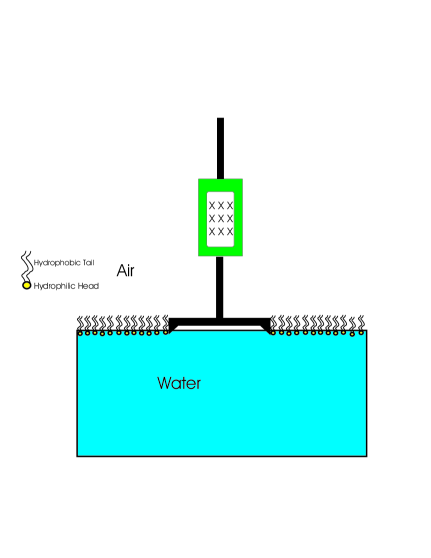
Because we have designed the main elements of the microrheological methods to probe the system from below the trough, we can access the surface of the water with a standard torsion, knife-edge device. For this, we have constructed a removable device. Figure 11 shows a schematic. The key elements are the suspension of a circular Teflon disk by a torsion wire. The support for the disk also contains a magnet coil (green rectangle in Fig. 11). This coil is situated within a larger coil that generates a magnetic field, indicated by the x’s in Fig. 11. There is additionally a fixed magnet attached to the coil on the disk support.
The coils serve a dual purpose. With the coils, we are able to both measure the angular position of the disk and provide an external torque to the disk to drive it at a defined frequency. The details of measuring the complex shear modulus with this method are provided in Ref. GKMD97 . The coils and torsion pendulum match the specifications reported in Ref. GD98 . We have modified the support structure to allow for portability of the device.
The primary motivation for building this apparatus was the need to measure properties of Langmuir monolayers and monolayer-protein complexes simultaneously on multiple length scales. It is worthwhile to briefly discuss another important capability of this system. Using the Teflon disk, one can apply a known macroscopic strain to the system. One can then use the microrheology measurements to determine the effect of strain on the local linear response of the samples. In other words, one can probe the linear response of a system that has been put in a non-linear state by external strain.
I Acknowledgements
We acknowledge the support of NSF-DMR-0354113. We also thank Thomas Fischer for helpful discussions. R. Walder acknowledges support through a travel fellowship from the Institute for Complex Adaptive Matter. C.F. Schmidt acknowledges support by the DFG/ SFB755 Nanoscale Photonic Imaging and by the DFG Center for Molecular Physiology of the Brain (CMPB).
References
- (1) C. F. Brooks, G. G. Fuller, C. W. Frank and C. R. 15, 2450 (1999).
- (2) W. D. Harkins and J. G. Kirkwood, J Chem Phys 6, 53 (1938).
- (3) L. E. Copeland, W. D. Harkins and G. E. Boyd, J Chem Phys 10, 357 (1942).
- (4) M. Sacchetti, H. Yu and G. Zografi, Rev Sci Instr 64, 1941 (1993).
- (5) D. K. Schwartz, C. M. Knobler and R. Bruinsma, Phys Rev Lett 73, 2841 (1994).
- (6) R. J. Mannheimer and R. S. Schechter, J. Coll. Inter. Sci. 32, 195 (1970).
- (7) S. S. Feng, R. C. MacDonald and B. M. Abraham, Langmuir 7, 572 (1992).
- (8) B. M. Abraham, K. Miyano, S. Q. Xu and J. B. Ketterson, Rev Sci Instr 54, 213 (1983).
- (9) J. Kr gel, S. Siegel, R. Miller, M. Born and K.-H. Schano, Colloids and Surfaces A 91, 169 (1994).
- (10) R. S. Ghaskadvi, J. B. Ketterson, R. C. MacDonald and P. Dutta, Rev Sci Instr 68, 1792 (1997).
- (11) S. Hȧrd and H. Löfgren, Journal Colloids and Interface Science 60, 529 (1976).
- (12) D. Langevin, Journal Colloid Interface Science 80, 412 (1981).
- (13) R. S. Ghaskadvi and M. Dennin, Review of Scientific Instruments 69, 3568 (1998).
- (14) B. D. Hughes, B. A. Pailthorpe, L. R. White and W. H. Sawyer, Biophys. J. 37, 673 (1982).
- (15) P. G. Saffman and M. Delbruck, Proc. Nat. Acad. Sci. USA 72, 3111 (1975).
- (16) J. F. Klingler and H. M. McConnell, Journal of Physical Chemistry 97 6096 (1993).
- (17) P. Steffen, et al., Journal of Chemical Physics 115, 994 (2001).
- (18) A. T. Ivanova, J. Ignes-Mullol, and D. K. Schwartz, Langmuir, 17, 3406 (2001).
- (19) S. Wurlitzer, P. Steffen, and Th. M. Fischer, Journal Of Chemical Physics 112, 13 (2000).
- (20) P. Steffen, P. Heinig, S. Wurlitzer, Z. Khattari, and Th. M. Fischer, Journal Of Chemical Physics 115, 2 (2001).
- (21) S. Wurlitzer, C. Lautz, M. Liley, C. Duschl, and Th. M. Fischer, J. Phys. Chem. B 105, 182 (2001).
- (22) M. Sickert, and F. Rondelez, Physical Review Letters 90, 12 (2003).
- (23) B. Schnurr, F. Gittes, F.C. MacKintosh, and C.F. Schmidt Macromolecules 30, 7781 (1997).
- (24) A.J. Levine and T.C. Lubensky, Physical Review Letters 85, 1774 (2000).
- (25) F. Gittens, B. Schnurr, P. D. Olmstedt, F. C. MacKintosh, and C. F. Schmidt, Phys. Rev. Lett 74, 3286 (1997).
- (26) F. C. MacKintosh and C. F. Schmidt, Curr. Opin. Collid and Interf. Sci. 4, 300 (1999).
- (27) A. Ashkin, J. M. Dziedzic, J. E. Bjorkholm, and S. Chu, Optics Letters 11, 5 (1986).
- (28) Nima Technology Ltd Surface Pressure Sensor Type PS4, The Science Park, Coventry, CV4 7EZ, England
- (29) Olympus America Inc., Model 5-UL155, 3500 Corporate Parkway P.O. Box 610 Center Valley, PA
- (30) Cohu Intensified CCD Camera Mod. 5515-2001, 3912 Calle Fortunada, San Diego, CA 92123-1827
- (31) Spectra Physics Model BL-106C, 1335 Terra Bella Avenue Mountain View, CA 94039
- (32) Olympus America Inc., Model 1-UM575, 3500 Corporate Parkway P.O. Box 610 Center Valley, PA
- (33) M. J. Lang, and S. M. Block, Amer. Jour. of Phys. 71, 201 (2003).
- (34) E. Helfer, S. Harlepp, L. Bourdieu, J. Robert, F.C. MacKintosh, and D. Chatenay, Physical Review Letters 85, 2 (2000).
- (35) New Focus Model 2309, 2584 Junction Avenue San Jose, CA 95134.
- (36) M. W. Allersma and F. Gittes and M. J. Castro and R. J. Stewart adn C. F. Schmidt, Biophys. Jour. 74, 1074 (1998).
- (37) F. Gittes and C. F. Schmidt, Optics Letters 23, 7 (1998).
- (38) K. Addas, C. F. Schmidt, and J. Tang, Physical Review E 70, (2004).