Casimir torque between corrugated metallic plates
Abstract
We consider two parallel corrugated plates and show that a Casimir torque arises when the corrugation directions are not aligned. We follow the scattering approach and calculate the Casimir energy up to second order in the corrugation amplitudes, taking into account nonspecular reflections, polarization mixing and the finite conductivity of the metals. We compare our results with the proximity force approximation, which overestimates the torque by a factor 2 when taking the conditions that optimize the effect. We argue that the Casimir torque could be measured for separation distances as large as 1
1 Introduction
The relevance of the Casimir effect [1] in connection with micro and nano-electromechanical systems (MEMS and NEMS) has been recently highlighted [2, 3, 4, 5, 6]. The attractive Casimir force can lead to permanent adhesion of the movable parts of MEMS and NEMS when they are close enough, a phenomenon known as ‘stiction’, resulting in malfunctioning of these devices. On the other hand, the Casimir effect may provide novel actuation schemes [7, 8] with promising potential applications.
Besides the usual normal Casimir force between metallic or dielectric plates, the lateral Casimir force between corrugated plates [9, 10] can also be used for micro-mechanical control. Very recently, two devices based on the lateral Casimir force were theoretically proposed: a rack and pinion device [11], which is actuated by the lateral Casimir force between a cylinder with a corrugated surface and a corrugated plane plate, and a Casimir ratchet [12], driven by the lateral Casimir force between a plate with a symmetric corrugation and a plate with an asymmetric corrugation.
The experimental results for the lateral Casimir force were first compared with a theoretical analysis [9, 10] based on the proximity-force approximation (PFA), or Derjaguin approximation [13, 14]. Within this approximation, the Casimir energy for non-planar surfaces is obtained by simply averaging the energy for parallel planes over the local separation distance. This approximation holds when the corrugation period is much larger than the average separation distance so that the surfaces are nearly plane in the scale of [15]. It is extremely important to check the accuracy of this approximation, since it was widely employed for comparison with experimental results for the (normal) Casimir force between curved surfaces [16, 17, 18, 19] (see Ref. [20] for a more detailed discussion and a review on recent theoretical advances).
We have computed the lateral force beyond the PFA [21, 22] by employing the scattering approach [23], which takes into account the finite conductivity of the metallic plates as well as diffraction and polarization mixing. The corrugation is treated as a small perturbation of the plane geometry, and the lateral force is computed up to second order in the corrugation amplitudes and for each plate. The perturbation expansion holds as long as but arbitrary relative values of and are allowed, with the PFA regime corresponding to the limit This formalism was also employed to compute the roughness correction to the Casimir force [24] and more recently the lateral Casimir-Polder force [25, 26]. Beyond-PFA theories for uni-axial corrugation on perfect reflecting plates were first reported by Emig et al for both perturbative [27] and nonperturbative [28] regimes.
The lateral Casimir force results from breaking the translational symmetry along directions parallel to the plates [29]. A more general situation occurs when the corrugations are not aligned, so that the Casimir energy depends on the relative orientation between the two plates, and a Casimir torque arises [30] (see figure 1). In this paper, we review the main physical properties of this effect. Whereas the formalism developed in Refs. [27, 28] requires the existence of a direction of translational symmetry (so as to allow for a convenient definition of field polarizations which are not coupled by the nonspecular reflection in this case), the scattering approach [23, 24] allows for a more general situation since it explicitly takes the coupling between different polarizations into account. Thus, the scattering approach allows one to consider the geometry with rotated corrugated plates, as long as the corrugation amplitudes remain the smallest length scale as discussed above.
Thanks to the high sensitivity of torsion balance techniques [31], the Casimir torque between corrugated plates provides an attractive way to measure nontrivial (i.e. beyond-PFA) geometry effects. The use of torsion balances has also been proposed to measure the Casimir torque between two (plane) birefringent dielectric plates [32] (see also [33, 34, 35, 36]). For the proposed separation distances around 100 nm [32], the Casimir torque for corrugated plates is up to three orders of magnitude larger than the torque between birefringent plates, for comparable values of the separation distance and plate area, and taking realistic values for the corrugation amplitudes and the finite conductivity of the metallic plates. This could allow one to perform the experiment at larger separation distances, thus minimizing problems related to plate parallelism.
2 Casimir energy for corrugated plates
We assume that both plates have sinusoidal corrugation profiles with the same period and amplitudes and The corrugation lines of the bottom plate are along the direction (ie, the surface profile depends only on ). The top plate position along the axis is (by symmetry the energy does not depend on the position along the axis), and is the rotation angle. corresponds to the configuration where the corrugation lines are aligned with the surface crests facing each other (see figure 1). This is the configuration corresponding to the global energy minimum as discussed below.
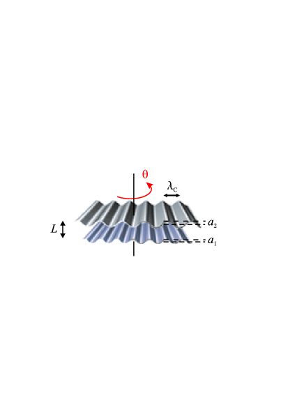
The top plate lateral dimensions are and and is the average separation distance (along the direction). Both plates are assumed to be very large compared to (so that border effects are negligible) as well as compared to The Casimir energy correction is then calculated to order [30]:
| (1) |
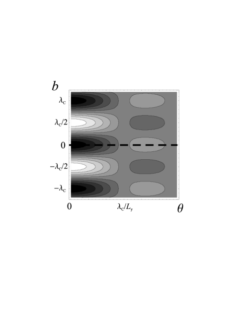
where and is a response function which also depends on the separation distance In figure 2, we plot the level curves of the Casimir energy correction (in arbitrary units) as a function of and . Since is always negative, the Casimir energy has global minima at and , , , … and local minima around (minimum of ) and , , …
If we start from and rotate the top plate around its center, we follow the dashed line shown in figure 2. For the plate is attracted back to the minimum at without sliding laterally. On the other hand, if the plate is released after a rotation of its subsequent motion will be a combination of rotation and lateral displacement. In the next section, we compute the Casimir restoring torque for the case of pure rotations with small rotation angles.
3 Casimir torque
The Casimir torque, given by
is maximum at where it is given by
| (2) |
As could have been expected, the torque per unit area is proportional to the length of the corrugation lines , which provides the scale for the moment arm.
We compute the response function using the plasma model with plasma wavelength nm (corresponding to gold-covered plates). In order to fix the numbers given as examples below, we take m and corrugation amplitudes such that (to be compared with in the lateral force experiment [9, 10], where and were unequal). Note that a change of these values is easily taken into account by using the scaling law (2).
If we also choose the corrugation period as in the lateral force experiment (), we find, at , approximately three orders of magnitude larger than the torque per unit area for birefringent plates calculated in Ref. [32] for the most favorable configuration at the same separation distance. The much larger figures found in our case should allow one to perform the experiment at larger separation distances.
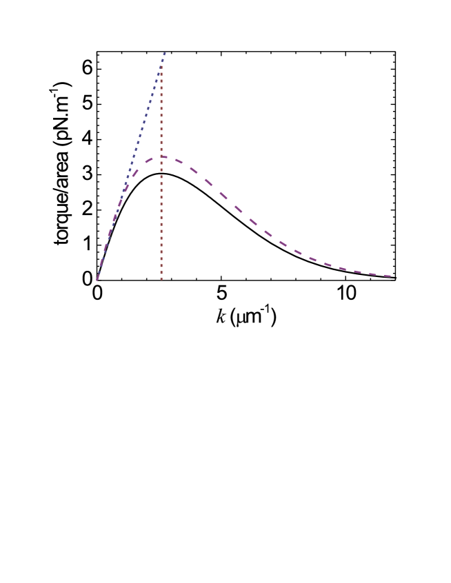
At any given value of , the torque between corrugated plates can be made larger by choosing the corrugation period so as to maximize For separation distances above 50 nm, this corresponds to or . In figure 3, we plot the torque as a function of for (solid line). The maximum at is indicated by a vertical dotted line. We also show the values obtained from the model with perfect reflectors (dashed line). They overestimate the torque by near the peak region.
We recover the second-order PFA result for the Casimir torque from eq. (2) by taking the limit . The response function satisfies the general ‘proximity force theorem’ [21] where is the Casimir energy per unit area for parallel planes. We thus find:
| (3) |
According to eq. (3), the torque grows linearly with in the PFA (dotted straight line in figure 3). Figure 3 shows that the scattering curve is very close to the PFA straight line when as expected (). However, the discrepancy increases with and at the peak value the PFA overestimates the torque by . A detailed discussion of the ratio for several separation distances is presented in Ref. [22].
4 Conclusion
As in the case of the lateral force, the Casimir torque between corrugated metallic plates might have potential applications in the design of MEMS and NEMS. We have studied the Casimir torque with the help of the scattering approach, which provides an exact result for the second-order energy correction.
This torque is up to three orders of magnitude larger than the torque between birefringent dielectric plates for comparable separation distance and area. The measurement of the Casimir torque with corrugated plates would provide a direct demonstration of a non-trivial (beyond PFA) geometry dependence of the Casimir energy.
RBR and PAMN thank FAPERJ, CAPES, CNPq and Institutos do Milênio de Informação Quântica e Nanociências for financial support. AL acknowledges partial financial support by the European Contract STRP 12142 NANOCASE.
References
References
- [1] Casimir H B G, 1948 Proc. K. Ned. Akad. Wet. 51 793.
- [2] Serry F M,Walliser D and Maclay G J, 1998 J. Appl. Phys. 84 2501
- [3] Buks E and Roukes M L, 2001 Europhys. Lett. 54 220
- [4] Buks E and Roukes M L 2001 Phys. Rev. B 63 033402
- [5] Capasso F, Munday J N, Iannuzzi D and Chan H B, 2007 IEEE J. Selected Topics Quantum Electronics 13 400 and references therein.
- [6] Esquivel-Sirvent R, Reyes L and Bárcenas J, 2006 New J. Phys. 8 241 and references therein.
- [7] Chan H B, Aksyuk V A, Kleiman R N, Bishop D J and Capasso F, 2001 Science 291 1941.
- [8] Chan H B, Aksyuk V A, Kleiman R N, Bishop D J and Capasso F, 2001 Phys. Rev. Lett. 87 211801
- [9] Chen F, Mohideen U, Klimchitskaya G L and Mostepanenko V M, 2002 Phys. Rev. Lett. 88 101801
- [10] Chen F, Mohideen U, Klimchitskaya G L and Mostepanenko V M, 2002 Phys. Rev. A 66 032113.
- [11] Ashourvan A, Miri M, Golestanian R, 2007 Phys. Rev. Lett. 98, 140801.
- [12] Emig T, 2007 Phys. Rev. Lett. 98, 160801.
- [13] Derjaguin B V, 1934 Kolloid Z. 69 155
- [14] Derjaguin B V and Abrikosova I I, 1957 Sov. Phys. JETP 3 819
- [15] Genet C, Lambrecht A, Maia Neto, P A and Reynaud S, 2003 Europhys. Lett. 62 484.
- [16] Ederth T, 2000 Phys. Rev. A 62 062104
- [17] Chen F et al 2004 Phys. Rev. A69 022117
- [18] Decca RS et al, 2005 Annals Phys. (NY) 318 37
- [19] Brown-Hayes M, Dalvit DAR, Mazzitellli FD, Kim WJ and Onofrio R, 2005 Phys. Rev. A 72 052102
- [20] Reynaud S, Maia Neto PA and Lambrecht A, in the present issue.
- [21] Rodrigues R B, Maia Neto, P A, Lambrecht A and Reynaud S, 2006 Phys. Rev. Lett. 96 100402
- [22] Rodrigues R B, Maia Neto, P A, Lambrecht A and Reynaud S, 2007 Phys. Rev. A 75, 062108.
- [23] Lambrecht A, Maia Neto, P A and Reynaud S, 2006 New J. Phys. 8 243.
- [24] Maia Neto PA, Lambrecht A and Reynaud S, Europhys. Lett. 69, 924 (2005); Phys. Rev. A 72 (2005) 012115 .
- [25] Dalvit DAR, Maia Neto PA, Lambrecht A and Reynaud S, 2007 arxiv: 0709.2095
- [26] Dalvit DAR, Maia Neto PA, Lambrecht A and Reynaud S, in the present issue.
- [27] Emig T et al, 2003 Phys. Rev. A 67 022114
- [28] Büscher R and Emig T, 2005 Phys. Rev. Lett. 94 133901
- [29] Golestanian R and Kardar M, 1997 Phys. Rev. Lett. 78 3421
- [30] Rodrigues R B, Maia Neto P A, Lambrecht A and Reynaud S, 2006 Europhys. Lett. 76 822
- [31] Gundlach JH, 1999 Meas. Sci. Technol. 10 454
- [32] Munday J N, Iannuzzi D, Barash Y and Capasso F, 2005 Phys. Rev. A 71 042102
- [33] Parsegian V A and Weiss G H, 1972 J. Adhes. 3 259
- [34] Barash Y, 1978 Izv. Vyssh. Uchebn. Zaved., Radiofiz. 12 1637
- [35] van Enk S J, 1995 Phys. Rev. A 52 2569
- [36] Torres-Gusmán J C and Mochán W L, 2006 J. Phys. A: Math Gen. 39 6791