Nondestructive interaction-free atom-photon controlled-NOT gate
Abstract
We present a probabilistic (ideally 50%) nondestructive interaction-free atom-photon controlled-NOT gate, where nondestructive means that all four outgoing target photon modes of the gate are available and feed-forwardable. Individual atoms are controlled by a stimulated Raman adiabatic passage transition and photons by a ring resonator with two outgoing ports. Realistic estimates we obtain for ions confined in a Paul trap around which the resonator is mounted show that a strong atom-photon coupling can be achieved. It is also shown how the resonator can be used for controlling superposition of atom states.
pacs:
03.67.Lx, 03.65.Ud, 42.50.VkI INTRODUCTION
Individual qubits with the help of which we attempt to build our would-be quantum computers are fragile because we must have full control over the states of each of them separately and of all of them collectively within any time window. In many proposals qubits are held in traps—electrical, magnetic, or optical. Controlling their states in traps over time and getting information from them during calculations can decohere and unstabilize them. The less energy transferred by probes, usually flying qubits, to a qubit sitting in a trap, the better. It would be the best to have no energy transfer at all. Quantum mechanics provides a way to do this. Whenever we fail to detect a quantum system in one of the paths it would take to interfere with itself, we “erase” the interference fringes we would have got, if we had not carried out any detection or measurement at all Renninger (1960); Dicke (1981); Pavičić (1986). Dicke called such a measurement an interaction-free measurement Dicke (1981) and Elitzur and Vaidman realized that such measurements might be useful whenever we do not want to transfer energy to a measured object Elitzur and Vaidman (1993). The measurements are also called energy-exchange-free Pavičić (1996), absorption-free Mitchison and Massar (2001), and counterfactual Mitchison and Jozsa (2001) measurements, as well as quantum interrogations Gilchrist et al. (2002).
Two implementations of interaction-free measurements in quantum computation have recently been proposed. One, proposed by Richard Jozsa Jozsa (1999), considers atoms as quantum computers (or parts of them) and flying qubits (photons) as their switches. Thus one of the two possible states of an atom resulting from a “computation” can be read “for free,” with no transfer of energy to the atom, i.e., without the “computer” actually running. Unfortunately, it turns out that the other state cannot be obtained for free Mitchison and Jozsa (2001). The controlled-NOT (CNOT) gate used in this approach has photon states as its control qubits and output register states as its target qubits.
The other proposal considers interaction-free measurements that are used to implement essential parts of quantum computations, notably CNOT gates and entanglement Azuma (2003, 2004); Gilchrist et al. (2002); Horodecki (2001); Méthot and Wicker (2001). CNOT gates are essential for quantum computing because they enable us to set up any quantum gate and therefore to implement any available algorithm. Entanglement appears in almost all blueprints of quantum computer candidates.
In constructing an interaction-free CNOT gate, Hiroo Azuma Azuma (2003) uses a positron as a straight moving control qubit that blocks ( times, where ) the paths of a zig-zagging electron—a target qubit. The CNOT gate is constructed not directly but using Bell-basis measurements by the method of Gottesman-Chuang Gottesman and Chuang (1999). In the Méthot-Wicker method, the qubits of the CNOT gate are two-level atoms, and photons only pass information between atoms Méthot and Wicker (2001). Gilchrist, White, and Munro Gilchrist et al. (2002) do use atoms as control qubits and photons as target qubits in a quantum Zeno setup, but to obtain a gate which could be called a destructive CNOT gate, since one of the target qubits must be destroyed and therefore one of the four outputs of the standard CNOT gate is not available.
In this paper we propose a nondestructive CNOT gate in which a two-level atom in a trap is the control qubit and a photon interrogating it—without transferring a single quantum of energy to it—is the target qubit. “Nondestructive” means that all four modes of the gate are available. Zhao et al. (2005) The proposal is an elaboration of the CNOT-gate setup put forward in Ref. (Pavičić, 2005, p. 166). A particular feature of the gate is that the target qubit can also physically control its control qubit by preventing the latter from entering into a superposition of its two available states. We carry out this interaction-free interrogation with the help of a photon resonator, and we prepare the atom by stimulated Raman adiabatic passage, STIRAP.
We organize the paper as follows. In Sections II and III we briefly present those details of interaction-free and STIRAP experiments (respectively) that are indispensable for understanding the construction of our CNOT gate. In Sec. IV we present the interaction-free CNOT gate itself, and in Sec. V an interaction-free control of superposition. The conclusion of the paper is given in Sec. VI.
II THE RESONATOR
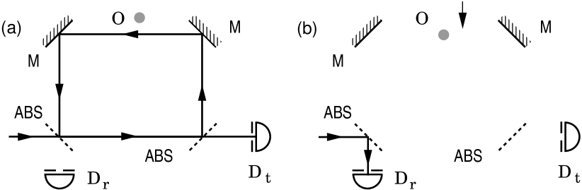
Let us consider the setup proposed by Paul and Pavičić in 1996 Paul and Pavičić (1996); Pavičić (1996); Paul and Pavičić (1997) and shown in Fig. 1. The predictions were confirmed in an actual experiment carried out by Tsegaye, Goobar, Karlsson, Björk, Loh, and Lim in 1998 Tsegaye et al. (1998).
We make use of a resonator which consists of two perfect mirrors and two highly asymmetrical mirrors that determine photon round trips as shown in Fig. 1. Other setups that minimize reflection losses are also possible Paul and Pavičić (1996, 1997). A laser beam enters the resonator through highly asymmetrical beam splitter ABS. When there is no object in the resonator, an incoming laser beam is almost completely transmitted into detector Dt. When there is an object, the beam is almost totally reflected into detector Dr. To increase efficiency, frustrated total reflection (which is an optical version of quantum mechanical tunnelling) can be used instead Paul and Pavičić (1996, 1997); Pavičić (2000). Thus the reflectivity can reach 0.9999 or higher. The uniqueness of the reflectivity at the beam splitters and perfect mirrors is assured by choosing the orientation of the polarization of the incoming laser beam perpendicular to the plane of incidence. The source of the incoming beam should be a continuous wave (cw) laser (e.g., Nd:YAG), because of its coherence length (up to 300 km) and because of its very narrow linewidth (down to 10 kHz in the visible range).
Each subsequent round trip contributes to a geometric progression whose infinite sum in the plane wave approach yields the total amplitude of the reflected beam:
| (1) |
where is the phase added by the round trip, is the frequency of the incoming beam, is the round-trip time, and is the resonance frequency corresponding to a wavelength which satisfies , where is the round-trip length of the cavity and is an integer. We see that, in the long run, for any and we get no reflection at all—i.e., no response from —if nothing obstructs the round trip, and almost a perfect reflection when the object blocks the round trip and is close to one. In terms of single photons (obtained by attenuating the intensity of the laser until the chance of having more than one photon at a time becomes negligible) the probability of detector reacting when there is no object in the system is zero. A response from indicates an interaction-free detection of an object in the system. The probability of the response is , the probability of making the object absorb the photon , and the probability of a photon exiting into detector .
Detailed wave packet calculations based on classical optical interference (analogous to the calculations for laser resonators) are carried out in Refs. Paul and Pavičić (1997, 1998); Pavičić (2000) and they yield the following efficiencies of the suppression of the reflection () into and of the throughput () into when there is no object in the resonator:
| (2) |
where is a measure of overall losses and
| (3) |
where is the coherence time and the round-trip time.
In effect, the resonator has to be “charged” to yield a superposition, i.e., we have to allow the beam a sufficient number of round-trips to build up a destructive or constructive interference even when it contains just one photon. This corresponds to the sum which we used to obtain Eq. (1) and it is shown in Fig. 2.

Now the difference between the classical and the quantum picture of interference lies in the statistical behaviour of the flying quantum system—the photon. The classical approach does not permit an interaction-free detection, because there is always an exchange of energy, e.g. . In the quantum approach, there can be no exchange of energy smaller than a quantum of energy corresponding to a single photon, and therefore only in the long run and on average the quantum energy transferred to an object does equal the classical energy.
Therefore we cannot narrow down the time window so as to make the coherence time less than the time required for interference to build up (at least 100 round trips). If we did so, a photon could not enter the resonator whether or not the object was in the photon path. As a consequence, downconverted photons (the signal to enter the resonator and the idler to control the event) are not suitable sources of photons, because their coherence time is too short (in the range of picoseconds). The use of a cw laser or a low emission LED and their inability to control the number of photons within the time window do not, however, pose a problem to our interaction-free CNOT gate, because we have two distinct outgoing ports, and because the time required for a sufficient number of round-trips is a few nanoseconds, which is short enough for use in quantum computation, where the decoherence typically ranges between nanoseconds and seconds.
III DARK STATES AND SUPERPOSITIONS
The purpose of interaction-free detection of a macroscopic object is to wipe out photon interference fringes so as to put the object in a photon path. In the case of atoms we do not physically block the photon path but make them opaque or transparent by bringing them into states in which they can or cannot absorb a photon of a chosen frequency. This also means that if an atom can be in a superposition of such two states, its interaction-free interrogation by a photon will prevent it from entering the superposition. In this section we present a setup which can be used to make an atom (in)visible to a photon in a resonator and to build up a CNOT gate.
Let us consider the rubidium isotope 87Rb Yu et al. (2004). (We can use many other atoms and ions that enable scheme presented below; e.g., 40Ca+ that we discuss in the next section.) It has the closed shells , , and one electron in the shell, which is pushed below the and shells by spin–orbit interaction. Thus 87Rb behaves like a system with one electron in the ground state. The total angular momentum is given by J=L+S. For the ground state , we have and and therefore . The first excited states are the states and , corresponding to , , , and , respectively. They are separated by the spin–orbit interaction . We will consider only .
The total nuclear angular momentum K combines with J to give the total angular momentum of the atom: . 87Rb has , and its ground states are split by hyperfine interaction into doublets with . Now we apply an external magnetic field B to the atom to split the levels into magnetic Zeeman sublevels with magnetic quantum numbers . The levels are given in Fig. 3 (cf. Ref. Sarkisyan et al. (2005)).
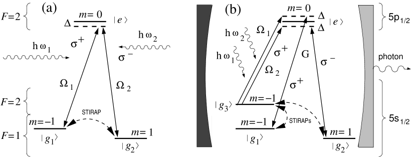
To excite and deexcite electrons between and we must use circularly polarized photons with angular momentum and two additional degrees of freedom (eigenvalues of ) denoted Messiah (1965). Linearly polarized photons cannot be used because the selection rules require for them.
When an atom absorbs a circularly polarized photon, it absorbs its energy and receives its angular momentum in its transition from the ground state to the excited state, and therefore the following selection rules must be met:
| (4) |
When a photon is emitted, the same selection rules must be observed. Thus for we get a circularly polarized photon and for a linearly polarized photon.
By solving the Schrödinger equation for our three-level system
| (5) |
we arrive (after starting with a more general Hamiltonian, doing some approximations, and re-introducing an intermediate form of the wave function) at the following Hamiltonian
| (9) |
where Rabi frequencies and (coefficients of the general solution to Eq. (5)) correspond to two pump laser beams of frequencies and that are detuned from resonance for . Hamiltonian (9) has three eigenstates that are linear combinations of , , and . One of them is Kuklinski et al. (1989):
| (10) |
We see that this state is completely independent of the intermediate state and that its eigenvalue—being zero—is independent of the Rabi frequencies and . We call states and dark states. Experimentally, we would obtain complete population transfer:
| (11) |
if we assumed , and this corresponds to switching on and off the second laser before switching on and off the first one. When the transfer is adiabatic (the laser beams are gradually switched on and off; for the adiabaticity criteria see Ref. Bergmann et al. (1998)), the system prepared in remains in this state at all times and the process is called STIRAP (Stimulated Raman Adiabatic Passage) Bergmann et al. (1998). The first laser beam (historically called the pump beam) is right-hand circularly polarized, denoted (because the transition requires it) and the second beam (historically called the Stokes beam) is left-hand circularly polarized, denoted (for ).
In a quantum computer, control of single states and is less important than control of their superposition . We can obtain a superposition by carrying out two simultaneous STIRAPs to and from a common third one as shown in Fig. 3. Many such designs for controlling and transferring superpositions have been proposed and implemented recently Pellizzari (1997); Bose et al. (1999); Yu et al. (2004). Cavities are often used instead of the second (Stokes) laser beams in each STIRAP Yu et al. (2004) and we consider such a design.
In Fig. 3 (b) a schematic is given of a strongly coupled atom-cavity system where the cavity is tuned (by shifting the mirrors) to the same frequency the Stokes beam would have for each transition. The cavity stimulates the population of levels and in the same way the Stokes laser fields would, and therefore the whole process is characterized by the following Hamiltonian:
| (15) |
where and is the atom-cavity coupling constant ( is the cavity mode volume). The photon which supports the cavity modes and the population of and levels eventually leaks from the cavity.
The state of the atom coupled to the cavity photon state is:
| (16) | |||||
Thus at the beginning of the STIRAP process, the system is in state , where means that there is no cavity photon coupled to . As and gradually increase, the system adiabatically evolves to state
| (17) |
and when the photon in the state leaves the cavity, the atom state jumps Plenio and Knight (1998) into the required superposition:
| (18) |
The jump is probabilistic and has a success probability of 50%.
IV INTERACTION-FREE CNOT GATE
In this section we show how the resonator described in Sec. II can be used to construct an interaction-free CNOT gate and then in Sec. V we discuss how to control and suppress an atom superposition obtained during quantum computation.
To construct an interaction-free CNOT gate, we substitute an atom, for example 87Rb of Sec. III, for the object in our resonator in Fig. 1. The 87Rb atom will be transparent to properly polarized photons of specific frequency when there is no electron in the ground level that a photon could excite to a higher level (a photon will not “see” the atom), and nontransparent when there is an electron populating the ground level.
In Sec. III we saw that a left-hand circularly polarized photon can excite an atom from its ground state () to its excited state (), and that the right-hand circularly polarized photon can excite the atom from () to (). So an -photon will “see” the atom in but will not “see” it when it is in . With an -photon, the opposite is true. The energy differences to the detuned excited level are the same, so both photons have the same frequency (as the “G part” of Fig. 3 (b): and ). We can induce a change of the atom from to and back by a STIRAP process, with two additional external laser beams, as explained in the previous section.
To build our CNOT gate we use the resonator we introduced in Sec. II. When a photon does not “see” the atom, its laser beam will interfere with itself in a resonator so that classical and quantum descriptions of photons give the same result Carmichael (1993); Mandel and Wolf (1995) as we already stressed in Sec. II. On the other hand, when we say that a photon “sees” an atom, that means that the atom would have absorbed the photon if it had come to it—in reality it cannot come to it because it is being reflected from the entrance to the resonator (see Fig. 1). To show that the atom in () is realistically opaque for () circularly polarized photons, we must resort to quantum theory and we shall come back to this point in the second half of this section.
This feature of our resonator approach that there are no photon loops in it when the atom is opaque is yet another advantage over a Zeno-like setup. We have to carry out quantum calculations only of a single absorption of a photon by the atom which reduces to a single strong atom-photon interaction while in a Zeno setup each photon loop inside a cavity with an opaque atom includes a strong photon-atom interaction. Cf. quantum calculations for a Zeno-like atom-photon interaction-free setup carried out by Luis and Sánchez-Soto. Luis and Sánchez-Soto (1998); Luis and Sánchez-Soto (1999a, b)
We feed our resonator with and linearly polarized photons to achieve the same conditions for round trips of both kinds of photons within the resonator. To the right of the atom we place a quarter-wave plate (QWP) to turn a -photon into an -photon and a -photon into an -photon. To the left of the atom we place a half-wave plate (HWP) to change the direction of the circular polarization and then another QWP to transform the polarization back into the original linear polarization. We denote the atom states as follows:
| (19) |
and take these atom states as control states and the atom itself to be our control qubit. We denote the photon states as follows:
| (20) |
and we take these photon states as the target states and the photons as target qubits. For example, means that the atom is in state and the photon is polarized along .
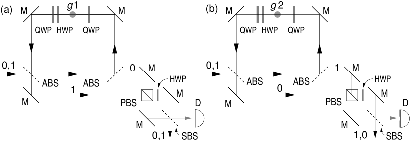
Now consider Fig. 4 (a). A photon in state does not “see” the atom in state and will therefore exit the resonator through the right port and will pass through the polarizing beam splitter PBS. A photon in state “sees” the atom in the state and therefore does not enter the resonator but goes down to the PBS and is reflected by it. Fig. 4 (b) refers to the atom in state . A photon in state sees it, goes down and passes through it, then goes through the half wave plate (HWP) which changes its state to . A photon in state does not see the atom and exits through the right port, reflects at PBS and changes to state when passing through HWP. This would (before the 50:50 beam splitter shown in Figure 4) give us a classical reversible CNOT gate and a nondestructive method of detecting the states of an atom.
However if we wanted to integrate the obtained CNOT gate into the circuits of a would-be quantum computer, then we should make the target operation unitary, i.e., we have to erase the which-path information the photons carry. We do so with the help of a symmetrical 50:50 beam splitter shown as SBS in Figure 4. Ideally, when detector D does not response, the target qubit will exit at the opposite side of the beam splitter so as to yield the following CNOT qubit values
| (21) |
Beam splitter SBS makes our CNOT probabilistic. Detector will ideally not response in half of the cases and this means that we would be able to forward on average every second target qubit to subsequent computation stages. Realistically, single photon detectors have recently reached the efficiency of 50% Rosfjord et al. (2006) and photon-number-resolving detectors the efficiency of 90% Rosenberg et al. (2005), so, the efficiency of the CNOT gate would be less than 50%. As a partial remedy, we could use two resonators simultaneously to obtain two CNOT gates consisting of one control atom qubit and two photon target qubits. Although statistically independent, their outcomes could support each other for getting more reliable final results, for obtaining middle stage results, and perhaps even for obtaining an error correction scheme for the target qubits (an algorithm for the purpose should be devised). This would enable us to compare our CNOT gate with the recent feed-forwardable all-optical CNOT gates. Pittman et al. (2003); Gasparoni et al. (2004); Pittman et al. (2005)
To estimate how efficiently an -photon will “see” an atom in state (and an -photon an atom in state) we have to calculate the probability with which an atom in () state would absorb a photon in () state. The total Hamiltonian for the atom-photon coupled system can be decomposed into three parts Carmichael (1993); Mandel and Wolf (1995):
| (22) |
where is the Hamiltonian of the two-level atom, of the photon field, and of their interaction. We assume that both the atom and the field are quantized so as to have
| (23) |
where is the atomic dipole moment, is the vector potential of the electric field of the laser beam and is the position of the atom, which we take to be fixed. The latter assumption is made on the following grounds.
Within an ion trap, ionized atoms can be confined to a region much smaller than the optical wavelength and their position can be controlled with a precision of under 10 nm. Mundt et al. (2002) The cavity (Sec. III) and the resonator can be put around the ion trap following a proposal recently elaborated theoretically by Maurer, Becher, Russo, Eschner, and Blatt Maurer et al. (2004) and Keller, Lange, Hayasaka, Lange, and Walther Keller et al. (2004) and confirmed experimentally by both groups Mundt et al. (2002); Keller et al. (2003) for 40Ca+. Our 87Rb cannot be easily ionized because 87Rb+ would lack its electron which forms our ground states and the first option for 87Rb- is which builds our excited states. Higher 87Rb- are difficult to obtain and are unstable. Stapelfeldt et al. (1994) But other stable ions, as e.g. 43Ca+ have abundant available states (43Ca+ has nuclear spin 7/2) with a structure that enables STIRAPs of the kind we analysed in Sec. III for 87Rb and can be used instead of 87Rb-. We however leave details of such a reformulation to a more realistic experimental future proposal simply because 87Rb structure and its Zeeman splitting has already been given a detailed experimentally tested model. Zhu et al. (1999); Sarkisyan et al. (2005) Zeeman splitting of other candidates, including 43Ca+, has not been sufficiently explored as of yet.
In the interaction picture we use the interaction Hamiltonian from Eq. (23) to obtain the following probability for the photon absorption by the atom in time Mandel and Wolf (1995):
| (24) |
where is the atomic frequency, is the laser field frequency, is the polar angle of the atomic Bloch vector, is the polarization vector, and the quantization volume.
This means that several conditions have to be satisfied to get a high absorption probability. First we have to tune the laser frequency close enough to the atomic frequency and this is achieved by the level of precision already experimentally reached in targeting individual ions trapped in Paul traps within an optical cavity as we mentioned above. This has also been achieved experimentally in cavity quantum electrodynamics (CQED) by Brune, Schmidt-Kaler, Maali, Dreyer, Hagley, Raimond, and Haroche Brune et al. (1996) already ten years ago. They obtained a coherent exchange of photons between the cavity field and individual atoms (vacuum Rabi oscillations). On the other hand, lasers can have linewidths that are less than 1 Hz and the precision of determining frequency of atomic transitions also approaches 1 Hz. Ido et al. (2005)
Next, for an atomic transition 1 (when , where ) the probability (24) is greatest for right circularly polarized photons and vanishes for left circularly polarized ones . Thus we have to orient the external magnetic field along the direction of the beam that hits the atom. As for term, means that the atom is in pure state and that its state is not populated at all.
What remains to be evaluated to estimate the level of coupling of the atom to the photon field is the quantization volume and the terms containing in the probability (24). The square root of the first two terms
| (25) |
is called the dipole coupling constant Carmichael (1993), or the rate of coupling of an atom to a single cavity mode Keller et al. (2004); Grangier et al. (2000) (usually with the assumption that ). In CQED and STIRAP cavities, is compared with spontaneous emission from the atom (transverse damping rate ) and with leaking out of the cavity (damping rate ). The calculations for these cavities differ from the one carried above, but the overall results are comparable. For the former cavities a strong coupling is achieved when is much larger than both and . Carmichael (1993); Keller et al. (2004); Grangier et al. (2000) One can achieve this by making a cavity as small as possible thereby decreasing and making larger, by choosing atoms with a narrower atomic linewidth , and by decreasing the linewidth of the cavity mode . With our resonator cavity, however, we do not have to care about spontaneous emission and/or leaking from the cavity because the interaction-free absorption (almost) never really excites the atom and the photon (almost) never really reaches the atom. So, our resonator cavity does not have to be small. In Sec. II we have seen that , where is the round-trip length of the cavity and is an integer. By picking a larger we get a larger cavity in which the birefringent optics would fit.
After integrating the terms containing in (24) over we get the rate of absorption: (the probability turns out to be a function of ). This rate is higher than the one we get in CQED experiments Brune et al. (1996) where the atoms move through a cavity with a velocity of over 100 m/s and nevertheless couple strongly to the cavity field within less than 100s. In our resonator we can achieve much longer and also shorter times (; the shortest time is limited by the resonance build-up time when a transparent object is in the resonator and the longest one by the coherence time of cw lasers). So, we can conclude that under realistic conditions the atom will be strongly coupled to our resonator cavity field. The shortest required times for the coupling have to be determined for a chosen atomic system.
We should add that the Stokes and pump beams for STIRAP switching can be used together with the resonator cavity inclined at a small angle to its beam because that beams are much stronger than the resonator beam and a small misalignment with the magnetic field will not significantly influence the transitions. Arimondo (1996); Bergmann et al. (1998) We cannot carry out STIRAP transitions and run interaction-free CNOT simultaneously because of the electromagnetically induced transparency (EIT) by the transitions. Arimondo (1996); Lukin (2003); Fleischhauer et al. (2005) If we wanted to carry out interaction-free interrogations of STIRAP transitions, we should employ transitions that are not used by the transitions, e.g., and as shown in Fig. 5.
V INTERACTION-FREE CONTROL OF SUPERPOSITION
Our design can also be used to control the STIRAP superposition of the states discussed in Sec. III, Eq. (18), in two ways. The first one is by determining a time span within which an atomic superposition can be built up and the second one is by suppressing the formation of atomic superposition using the interaction-free erasure of interference fringes obtained in Ref. Pavičić (1996).
In the STIRAP process presented in Sec. III the electron is moved from the state shown in Fig. 3 (b) into the superposition of the states and given by Eq. (18). Interaction-free detection can be used to determine, within a few microseconds, when the electron leaves state , as follows.
We use our interaction-free resonator with the interrogating paths perpendicular to the axis of the cavity and wave plates removed in order to probe the atom with a linearly polarized photon , denoted in Fig. 5 (a circularly polarized photon corresponding to the transition would also work). We tune the resonator and photons to the frequency that corresponds to a possible transition . When our resonator is applied to an atom in which a STIRAP transition is induced, its repeated interrogation will pinpoint the time of this transition. This is because the photon “sees” the electron if transition is possible and does not “see” it when it leaves . In the former case it exits at one port of the resonator and in the latter at the other. The photon cannot of course really excite the atom, because it cannot transfer any energy to it.

Assuming that a realistic round trip of our resonator can be reduced to a few cm and calculating Paul and Pavičić (1996) that 200 to 300 round trips (under 100 ns) are sufficient to establish interference within the resonator, we calculates that a laser has to be on for several s in order to detect whether or not an electron is in state , i.e., whether the atom is opaque or transparent. We must therefore reduce the intensity of a cw laser so as to obtain on average one photon within this time window.
The other way of controlling our STIRAP is to prevent building of superposition and forcing the electron into either state or state . For this purpose, we use two interaction-free resonators with interrogating paths oriented perpendicularly to the axis of the cavity and tuned to frequencies and with circularly polarized photons, as shown in Fig. 5. Linearly polarized photons corresponding to transitions to and , respectively, would also work. Note that the scheme with photons tuned to transitions and would not work, because, as shown in Sec. III, the atom is transparent to such photons in both cases—when there is no electron in states and and when STIRAPs are in progress. In the latter case we speak of electromagnetically induced transparency (EIT) Arimondo (1996); Lukin (2003); Fleischhauer et al. (2005).
VI CONCLUSION
In conclusion, we have obtained a probabilistic interaction-free CNOT gate in which two atom Zeeman states represent the control qubit and two photon polarization states represent the target qubit. The gate, which is a photon ring resonator, is robust because it does not transfer any energy to atoms in over 95% of tests. Unlike the previous atom-photon CNOT gate Gilchrist et al. (2002), this gate has all four modes available, because it has two exit ports for photons, each of which can let photons in both polarization states out, depending on the state the atom is in.
In Sec. IV we carried out quantum calculations and made realistic estimations for a possible experiment. If we confine ions (e.g., 40Ca+) to under 10 nm by using a Paul trap and mount the resonator around it, we arrive at the rate of absorption which is higher than in other experimentally tested cavities. This amounts to a strong coupling between the atoms in our ring cavity and its field modes.
The interaction-free resonator can also be used to control a stimulated Raman adiabatic passage (STIRAP) from an individual state to a state of superposition. We can control the time when an atom changes its state. Such detection takes under 1s.
Another control we can exert over qubits is to suppress atom-state superposition. The quantum system is altered without any energy transfer to the system in observation of the quantum indistiguishability principle, which states that no information can be acquired about the population of particular states which take part in a superposition.
Thus the interaction-free resonator can be used in quantum computation to manipulate qubits and to obtain information on them during computation without decohering their states. It is suitable for systems that can be scaled up because it is non-destructive, i.e., it does not destroy the output states, and because it provides information on the success of the CNOT-gate operation that can be used for subsequent manipulation of the same photon qubits. More specifically, we can amplify the null detections of detector D in Fig. 4 by combining two resonators, where one of them would give information on the output of the other.
Acknowledgements.
This work was supported by the Ministry of Science, Education, and Sport of Croatia, Project No. 0082222.References
- Renninger (1960) M. Renninger, Z. Physik 158, 417 (1960).
- Dicke (1981) R. H. Dicke, Am. J. Physics 49, 925 (1981).
- Pavičić (1986) M. Pavičić, Algebraico-Logical Structure of the Interpretations of Quantum Mechanics. Ph.D. Thesis (in Croatian), pp. 31–32 (University of Belgrade, 1986), Transl. into English in Ref. Paul and Pavičić (1998).
- Elitzur and Vaidman (1993) A. C. Elitzur and L. Vaidman, Found. Phys. 23, 987 (1993).
- Pavičić (1996) M. Pavičić, Phys. Lett. A 223, 241 (1996).
- Mitchison and Massar (2001) G. Mitchison and S. Massar, Phys. Rev. A 63, 032105 (2001).
- Mitchison and Jozsa (2001) G. Mitchison and R. Jozsa, Proc. R. Soc. Lond. A 457, 1175 (2001).
- Gilchrist et al. (2002) A. Gilchrist, A. G. White, and W. J. Munro, Phys. Rev. A 66, 012106 (2002).
- Jozsa (1999) R. Jozsa, Chaos, Solitons & Fractals 10, 1657 (1999).
- Azuma (2003) H. Azuma, Phys. Rev. A 68, 022320 (2003).
- Azuma (2004) H. Azuma, Phys. Rev. A 70, 012318 (2004).
- Horodecki (2001) P. Horodecki, Phys. Rev. A 63, 022108 (2001).
- Méthot and Wicker (2001) A. A. Méthot and K. Wicker, arXiv.org/quant-ph/0109105 (2001).
- Gottesman and Chuang (1999) D. Gottesman and I. L. Chuang, Nature 402, 390 (1999).
- Zhao et al. (2005) Z. Zhao, A.-N. Zhang, Y.-A. Chen, H. Zhang, J.-F. Du, T. Yang, and J.-W. Pan, Phys. Rev. Lett. 94, 030501 (2005).
- Pavičić (2005) M. Pavičić, Quantum Computation and Quantum Communication: Theory and Experiments (Springer, New York, 2005).
- Paul and Pavičić (1996) H. Paul and M. Pavičić, Int. J. Theor. Phys. 35, 2085 (1996).
- Paul and Pavičić (1997) H. Paul and M. Pavičić, J. Opt. Soc. Am. B 14, 1273 (1997).
- Tsegaye et al. (1998) T. Tsegaye, E. Goobar, A. Karlsson, G. Björk, M. Y. Loh, and K. H. Lim, Phys. Rev. A 57, 3987 (1998).
- Pavičić (2000) M. Pavičić, in Quantum Communication, Computing, and Measurement 2, edited by P. Kumar, G. M. D’Ariano, and O. Hirota (Kluwer/Plenum, New York, 2000), pp. 527–531.
- Paul and Pavičić (1998) H. Paul and M. Pavičić, Found. Phys. 28, 959 (1998).
- Yu et al. (2004) B. Yu, Z.-W. Zhou, Y. Zhang, G.-Y. Xiang, and G.-C. Guo, Phys. Rev A 70, 014302 (2004).
- Sarkisyan et al. (2005) D. Sarkisyan, A. Papoyan, T. Varzhapetyan, K. Blushs, and M. Auzinsh, J. Opt. Soc. Am. B 22, 88 (2005).
- Messiah (1965) A. Messiah, Quantum Mechanics (North-Holland, Amsterdam, 1965).
- Kuklinski et al. (1989) J. R. Kuklinski, U. Gaubatz, F. T. Hioe, and K. Bergmann, Phys. Rev. A 40, 6741 (1989).
- Bergmann et al. (1998) K. Bergmann, H. Theuer, and B. W. Shore, Rev. Mod. Phys. 70, 1003 (1998).
- Pellizzari (1997) T. Pellizzari, Phys. Rev. Lett. 79, 5242 (1997).
- Bose et al. (1999) S. Bose, P. L. Knight, M. B. Plenio, and V. Vedral, Phys. Rev. Lett. 83, 5158 (1999).
- Plenio and Knight (1998) M. B. Plenio and P. L. Knight, Rev. Mod. Phys. 70, 101 (1998).
- Carmichael (1993) H. Carmichael, An Open Systems Approach to Quantum Optics, Lecture Notes in Physics m18 (Springer-Verlag, Berlin, 1993).
- Mandel and Wolf (1995) L. Mandel and E. Wolf, Optical Coherence and Quantum Optics (Cambridge University Press, Cambridge, 1995).
- Luis and Sánchez-Soto (1998) A. Luis and L. L. Sánchez-Soto, Phys. Rev. A 58, 836 (1998).
- Luis and Sánchez-Soto (1999a) A. Luis and L. L. Sánchez-Soto, Phys. Rev. A 60, 56 (1999a).
- Luis and Sánchez-Soto (1999b) A. Luis and L. L. Sánchez-Soto, Phys. Lett. A 252, 130 (1999b).
- Rosfjord et al. (2006) K. M. Rosfjord, J. K. W. Yang, E. A. Dauler, A. J. Kerman, V. Anant, B. M. Voronov, G. N. Gol’tsman, and K. K. Berggren, Optics Express 14, 527 (2006).
- Rosenberg et al. (2005) D. Rosenberg, A. E. Lita, A. J. Miller, and S. W. Nam, Phys. Rev. A 71, 061803(R) (2005).
- Pittman et al. (2003) T. B. Pittman, M. J. Fitch, B. C Jacobs, and J. D. Franson, Phys. Rev A 68, 032316 (2003).
- Gasparoni et al. (2004) S. Gasparoni, J.-W. Pan, P. Walther, T. Rudolph, and A. Zeilinger, Phys. Rev. Lett. 93, 020504 (2004).
- Pittman et al. (2005) T. B. Pittman, B. C Jacobs, and J. D. Franson, Phys. Rev A 71, 052332 (2005).
- Mundt et al. (2002) A. B. Mundt, A. Kreuter, C. Becher, D. Leibfried, J. Eschner, F. Schmidt-Kaler, and R. Blatt, Phys. Rev. Lett. 89, 103001 (2002).
- Maurer et al. (2004) C. Maurer, C. Becher, C. Russo, J. Eschner, and R. Blatt, New J. Phys. 6, 94 (2004).
- Keller et al. (2004) M. Keller, B. Lange, K. Hayasaka, W. Lange, and H. Walther, New J. Phys. 6, 95 (2004).
- Keller et al. (2003) M. Keller, B. Lange, K. Hayasaka, W. Lange, and H. Walther, Appl. Phys. B 76, 125 (2003).
- Stapelfeldt et al. (1994) H. Stapelfeldt, P. Kristensen, U. Ljungblad, T. Andersen, and H. K. Haugen, Phys. Rev. A 50, 1618 (1994).
- Zhu et al. (1999) Y. Zhu, S. Wang, and N. M. Mulchan, Phys. Rev. A 59, 4005 (1999).
- Brune et al. (1996) M. Brune, F. Schmidt-Kaler, A. Maali, J. Dreyer, E. Hagley, J. M. Raimond, and S. Haroche, Phys. Rev. Lett. 76, 1800 (1996).
- Ido et al. (2005) T. Ido, T. H. Loftus, M. M. Boyd, A. D. Ludlow, K. W. Holman, and J. Ye, Phys. Rev. Lett. 94, 153001 (2005).
- Grangier et al. (2000) P. Grangier, G. Reymond, and N. Schlosser, Fortschr. Phys. 48, 859 (2000).
- Arimondo (1996) E. Arimondo, in Progress in Optics, edited by E. Wolf (Elsevier, Amsterdam, 1996), vol. XXXV, chap. V, pp. 257–354.
- Lukin (2003) M. D. Lukin, Rev. Mod. Phys. 75, 457 (2003).
- Fleischhauer et al. (2005) M. Fleischhauer, A. Imamoglu, and J. P. Marangos, Rev. Mod. Phys. 77, 633 (2005).