Light-driven liquid crystalline nonlinear oscillator under optical periodic forcing
Abstract
An all-optically driven strategy to govern a liquid crystalline collective molecular nonlinear oscillator is discussed. It does not require external feedbacks of any kind while the oscillator and a time-depending perturbation both are sustained by incident light. Various dynamical regimes such as frequency-locked, quasiperiodic, forced and chaotic are observed in agreement with a theoretical approach developed in the limit of the plane wave approximation.
pacs:
42.70.Df, 05.45.-a, 42.65.SfThe response of nonlinear oscillators to time-dependent external control parameter is well-known and has been investigated in a wide range of systems including physical Pikovsky01_book , chemical Kuramoto84_book and biological ones Winfree00_book . Periodic forcing may lead to entrainment or quasiperiodicity according to whether the ratio between the forcing frequency () and the natural frequency of the autonomous system () is rational or irrational. The natural limit cycle behavior of the oscillator may also be driven into more complex dynamics. Recent applications of periodic forcing such as the control of a chaotic chemical reaction Cordoba06 or the control of a microfluidic droplet emitter Willaime06 have emphasized the use of this technique to engineer controllable systems.
An optical forcing scheme to achieve a non-contact control of a nonlinear oscillatory system is limited to a few number of systems. A well-known example is the light-sensitive Belousov-Zhabotinsky reaction, which is a spatially extended system where a homogeneous time-periodic optical forcing allows to control pattern formation Lin04 . A liquid crystal light valve, where a two-dimensional external feedback and an additional quasistatic electric field have been used, is another example Gutlich05 . In contrast, a local optical periodic forcing on uniformly oscillating catalytic surface reaction has been investigated in Ref. Wolff03 , where the heating provided by a focused laser beam acts as the local external perturbation. To our knowledge the all-optical situation, where both the nonlinear oscillator and the time-dependent perturbation are supplied by light only, without need of an external feedback, has not been reported yet.
We propose an all-optical periodic forcing strategy to control a liquid crystalline molecular oscillator driven by light based on optical orientational nonlinearities of mesophases Tabiryan86_review . There is no need of external feedback owing to the strong light-matter coupling that occurs during the propagation of light through the optically anisotropic liquid crystal (LC) material. Indeed it is known that a LC under an intense laser field can be viewed as a collective molecular oscillator whose dynamics depends on the light-matter interaction geometry. Very rich director dynamics has been observed and confirmed theoretically at fixed light intensity. Among most studied geometries one can mention a circularly polarized beam at normal incidence Santamato86 ; Brasselet05 , an elliptically polarized beam at normal incidence Vella02 ; Krimer05_2 , an ordinary linearly polarized beam at oblique incidence Cipparrone93 or a linearly polarized beam at normal incidence having an elliptic intensity profile Piccirillo01 . More specifically, laser-induced nonlinear reorientation dynamics in LCs has retained some attention in the context of transition to chaos Demeter99 ; Carbone01 ; Demeter05 and chaotic rotations Vella03 ; Brasselet06 . In contrast to all previous studies performed at fixed intensity, the aim of the present work is to explore both theoretically and experimentally two representative light-LC interaction geometries when the intensity is periodically modulated.
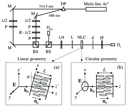
The observations are performed using the experimental set-up shown in Fig. 1 where the linear geometry refers to a linearly polarized light impinging at oblique incidence (typically few degrees) onto nematic film with the electric field perpendicular to the incidence plane [Fig. 1(a)]. The circular geometry corresponds to a circularly polarized light with normal incidence [Fig. 1(b)]. In both cases the autonomous system has a limit cycle behavior at the onset of a secondary Hopf bifurcation, where the reorientation amplitude ( and is the unperturbed director, which is the unit vector that represents the averaged local molecular orientation, see Fig. 1) acquires an oscillatory behavior with natural frequency . The periodic forcing is then achieved by sinusoidal perturbation of the intensity, . Here, is the intensity normalized to the reorientation threshold, which corresponds to the so-called optical Fréedericksz transition, and is the forcing amplitude.
We used in the experiment commercial nematic E7 from Merck which was placed between two glass substrates that were chemically treated to ensure homeotropic anchoring (molecules are perpendicular to the film walls). The incident beam is focused onto a nematic film of m thickness using a 150 mm focal length lens. The aforementioned general form of was obtained by combining two laser lines ( nm and nm) selected from a multi-line linearly polarized Argon-ion laser using a dispersion prism placed at the laser output. The total intensity of each of the two beams is controlled using independent combinations of a plate followed by a polarizer. The linear polarization of the -beam is continuously rotated owing to a rotating plate controlled by an electrical motor. The polarizer placed after the rotating plate ensures that -beam is polarized along the direction with the intensity whereas the intensity of the -polarized beam is kept fixed. Both beams then recombine through a beam splitter to generate an excitation light field whose total intensity is of the required form. Note that the forcing frequency () and amplitude () can be adjusted independently. Finally, a plate placed before the lens allows to switch between two geometries. Its optical axis is set along (at of) the -axis in the linear (circular) case.
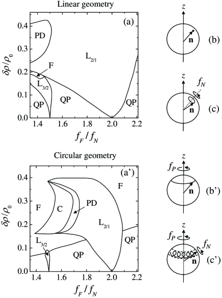
At first the total intensity, which is monitored by the photodiode (see Fig. 1), is increased smoothly from zero, setting . The homeotropic state remains stable below the Fréedericksz threshold. Above threshold the system settles either to a stationary distorted state (fixed point) in the linear case or to a state of uniform precession of the director around the -axis with the frequency (limit cycle) in the circular case as shown in Figs. 2(b,b’). A further increase of the intensity leads to a secondary supercritical Hopf bifurcation in both cases. At the onset of this instability, a new frequency associated with the oscillation of the reorientation amplitude appears as sketched in Fig. 2(c,c’). Forcing experiments are performed slightly above the secondary threshold (typically a few percent) ensuring that a system never reaches higher instabilities for both linear Demeter01 and circular geometry Brasselet05 .
Both the natural limit cycle at and the reorientation amplitude dynamics at are monitored by the time-dependent total intensity of the central part of the beam that emerges from the sample, , where the contribution depends on and . Indeed at fixed . In addition, the larger is, the stronger self-focusing effects are and is small when is fixed. Therefore the Fourier spectrum of can safely be associated with the one of since is constant. This is achieved by using an interferential filter operating at to get rid of the contribution where is modulated with frequency . The photodiode (see Fig. 1) thus collects the signal that will be further denoted as . We notice that we were able to fully characterize the director dynamics (i.e. its polar and azimuthal degrees of freedom) using a polarimetric analysis of the output beam, which is not shown in Fig. 1. However, only the polar degree of freedom is of interest in the presented results.
A rigorous description of the dynamical properties of nematics is well-established in a full hydrodynamic approach deGennes93_book . The basic equations are those of the director and the velocity field, which are coupled with the Maxwell’s equations that governs the propagation of light. The director equations are derived using the torque balance condition among the elastic, electric and viscous torques. The flow caused by the director reorientation was shown to lead to quantitative rather than to qualitative changes in both geometries Krimer05 ; Demeter05 within the range of intensity that has been explored here. Thus, the velocity is neglected in our study. In the calculations we used the plane wave approximation and assumed that the director depends only on and . Taking into account that the Maxwell’s equations were solved under the geometrical optics approximation. The latter are consequently reduced to a set of two ordinary differential equations for the amplitudes of the ordinary () and extraordinary () waves. Despite the simplification described the resulting set of equations is rather cumbersome and is not presented here explicitly. The complete bifurcation scenario for the autonomous system () is available for both linear Demeter01 and circular geometry Brasselet05 under the aforementioned approximations. The models developed there might straightforwardly be extended to the case of time-dependent intensity . As in previous studies, we used different representations to describe the director depending on the geometry. Such a choice is dictated by symmetry considerations. Then an expansion of the director components is performed in terms of orthogonal functions which satisfy the boundary conditions . Namely we took with and for linear geometry, whereas with and for the circular one. The Galerkin procedure was then used to obtain a set of nonlinear ordinary differential equations for the mode amplitudes or which was solved numerically using standard Runge-Kutta method. In fact it is enough to retain only a few number of modes for the director expansion to obtain a good accuracy for the calculated director components (better than ). Note that the Maxwell’s equations were solved at each step of numerical integration for time . We also introduce the total phase delay between the - and -waves across the whole film ( are the refractive indices), which is a global measure of the amplitude of reorientation Tabiryan86_review . The calculated will thus be compared with the measured .
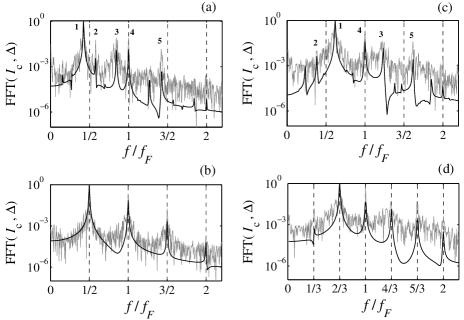
The calculated maps of dynamical regimes are shown in Fig. 2 in the plane, where the same material parameters as in Ref. Brasselet05 have been used. In addition, is taken approximately 1% above the secondary Hopf bifurcation threshold. For the sake of illustration the results are presented for a typical layer thickness m and a typical incidence angle (for the linear geometry only, see Fig. 1). These maps aim to show the generic dynamical behavior of the system and further quantitative comparison with experiments is done using the actual experimental values. We note however that the conclusions are unchanged under (i) cell thickness changes as long as the geometrical optics approximation is satisfied and (ii) incidence angle changes in the typical range 2-8∘ [for linear geometry] since the observed dynamics is mainly dictated by existence of the secondary Hopf instability Demeter01 . In both cases we focus our study on the region near 2:1 resonance which is known to be strong. An advantage of the system in question is that the entrainment region (the so-called Arnold’s tongue) which emanates from the point is rather wide, which facilitates its observation, see Fig. 2. Experimental evidence of entrainment is found by fixing the forcing amplitude and scanning the forcing frequency. The results for the linear geometry are shown in Fig. 4, where the power Fourier spectra of are plotted together with the spectra of its theoretical analog, the phase delay . Each panel corresponds to a measurement which lasted s, with decreasing from the panel (a) to (d). The spectra of and for a state within the 2:1 tongue [Fig. 4(b)] are characterized by a single frequency, , as expected. Outside the tongue and for sufficiently small , the system responds quasiperiodically. In that case the spectra of and are described by means of two incommensurable frequencies and that generate peaks at frequencies , and integers, as shown in Fig. 4(a,c). The 3:2 tongue is also observed and shown in Fig. 4(d). In this case the single frequency determines the dynamics, as expected.
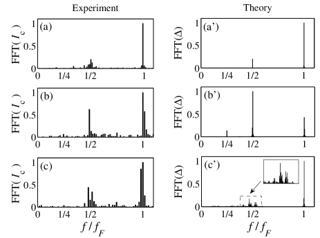
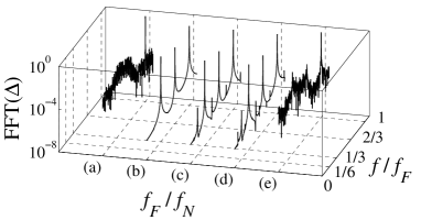
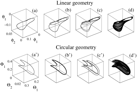
For higher forcing amplitude a forced regime (the F region in Fig. 2) was found which has as a unique characteristic frequency. When starting inside the 2:1 tongue and decreasing the forcing frequency (keeping the same value of ), a route to chaos via a cascade of period-doubling bifurcation was found for moderate to large forcing amplitudes (the PD and C regions in Fig. 2). The resulting typical trajectories are shown in Fig. 4 for both linear (at ) and circular (at ) geometries. In Fig. 5 the power spectra of (experiment) and (theory) are compared for the successive states from the sequence L PD C for the circular geometry. In particular the transition to a chaotic regime is accompanied by an abrupt frequency widening around . Such a behavior is predicted by theory as well [see Figs. 5(b’,c’)]. In addition, the characteristic presence of windows of regularity inside the chaotic region when varies at fixed has been found. There, the director dynamics is periodic. One of these windows is shown in Fig. 6 for , where a dynamics suddenly appears when the frequency is decreased. Period doubling then begins again with limit cycles having frequencies , , etc. and then once again break off to chaos.
In conclusion, we showed that an all-optical control scheme based on periodic forcing of the light intensity can be implemented in liquid crystalline materials. Two light-matter interaction geometries have been used for demonstration. Various dynamical regimes such as frequency-locked, quasiperiodic, forced or chaotic have been shown to result from the optical forcing. The theoretical study is carried out within the general framework involving Maxwell’s equations and the constitutive material equations. Fairly good qualitative agreement between theory and experiments is obtained in the entire range of the problem parameters. The polarization sensitivity of mesophases might also offer the possibility to extend present results to a periodic modulation of the polarization instead of the intensity.
This paper is dedicated to the memory of Prof. Lorenz Kramer who suddenly passed away on 05/04/2005. The preliminary idea of that work was discussed with him. We thank Prof. Michael Tribelsky for his valuable comments. EB thanks the Physics Laboratory of Ecole Normale Supérieure de Lyon in France for the use of its experimental facilities.
References
- (1) A. Pikovsky, M. Rosenblum and J. Kurths, Synchronization (Cambridge University Press, Cambridge, 2001).
- (2) Y. Kuramoto, Chemical Oscillations, Waves and Turbulence (Springer, Berlin, 1984).
- (3) A. T. Winfree, The Geometry of Biological Time (Springer, Berlin, 2000).
- (4) A. Córdoba, M. C. Lemos, and F. Jiménez-Morales, J. Chem. Phys. 124, 014707 (2006).
- (5) H. Willaime, V. Barbier, L. Kloul, S. Maine, and P. Tabeling, Phys. Rev. Lett. 96, 054501 (2006).
- (6) A. L. Lin, A. Hagberg, E. Meron and H. L. Swinney, Phys. Rev. E 69, 066217 (2004).
- (7) B. Gütlich, H. Zimmermann, C. Denz, R. Neubecker, M. Kreuzer and T. Tschudi, Appl. Phys. B 81, 927 (2005).
- (8) J. Wolff and H. H. Rotermund, New Journal of Physics 5, 60 (2003).
- (9) N. V. Tabiryan, A. V. Sukhov, and B. Y. Zel’dovich, Mol. Cryst. Liq. Cryst. 136, 1 (1986).
- (10) E. Santamato, B. Daino, M. Romagnoli, M. Settembre, and Y. R. Shen, Phys. Rev. Lett. 57, 2423 (1986).
- (11) E. Brasselet, T. V. Galstian, L. J. Dubé, D. O. Krimer, and L. Kramer, J. Opt. Soc. Am. B 22, 1671 (2005).
- (12) A. Vella, B. Piccirillo, and E. Santamato, Phys. Rev. E 65, 031706 (2002).
- (13) D. O. Krimer, L. Kramer, E. Brasselet, T.V. Galstian and L. J. Dube, J. Opt. Soc. Am. B, 22, 1681 (2005).
- (14) G. Cipparrone, V. Carbone, C. Versace, C. Umeton, R. Bartolino and F. Simoni, Phys. Rev. E 47, 3741 (1993).
- (15) B. Piccirillo, C. Toscano, F. Vetrano, and E. Santamato, Phys. Rev. Lett. 86, 2285 (2001).
- (16) G. Demeter and L. Kramer, Phys. Rev. Lett. 83, 4744 (1999).
- (17) V. Carbone, G. Cipparrone, and G. Russo, Phys. Rev. E 63, 051701 (2001).
- (18) G. Demeter, D. O. Krimer, and L. Kramer, Phys. Rev. E 72, 051712 (2005).
- (19) A. Vella, A. Setaro, B. Piccirillo, and E. Santamato, Phys. Rev. E 67, 051704 (2003).
- (20) E. Brasselet and L. J. Dubé, Phys. Rev. E 73, 021704 (2006).
- (21) G. Demeter and L. Kramer, Phys. Rev. E 64, 020701(R) (2001); E. Brasselet, Phys. Rev. E 72, 013701 (2005).
- (22) P. G. de Gennes and J. Prost, The physics of liquid crystals (Clarendon press, Oxford, 1993).
- (23) D. O. Krimer, G. Demeter and L. Kramer, Phys. Rev. E 71, 051711 (2005).