Air-clad fibers: pump absorption assisted by chaotic wave dynamics?
Niels Asger Mortensen
MIC – Department of Micro and Nanotechnology, NanoDTU, Technical University of Denmark, Ørsteds Plads, DTU-building 345 east, DK-2800 Kongens Lyngby, Denmark.
nam@mic.dtu.dk
http://www.mic.dtu.dk/nam
Abstract
Wave chaos is a concept which has already proved its practical usefulness in design of double-clad fibers for cladding-pumped fiber lasers and fiber amplifiers. In general, classically chaotic geometries will favor strong pump absorption and we address the extent of chaotic wave dynamics in typical air-clad geometries. While air-clad structures supporting sup-wavelength convex air-glass interfaces (viewed from the high-index side) will promote chaotic dynamics we find guidance of regular whispering-gallery modes in air-clad structures resembling an overall cylindrical symmetry. Highly symmetric air-clad structures may thus suppress the pump-absorption efficiency below the ergodic scaling law , where and are the areas of the rare-earth doped core and the cladding, respectively.
OCIS codes: (060.2280) Fiber optics and optical communications : Fiber design and fabrication, (060.2320) Fiber optics amplifiers and oscillators, (140.3510) Lasers and laser optics : Lasers, fiber.
References and links
- [1] A. Tünnermann, T. Schreiber, F. Röser, A. Liem, S. Höfer, H. Zellmer, S. Nolte, and J. Limpert, “The renaissance and bright future of fibre lasers,” J. Phys. B-At. Mol. Opt. Phys. 38(9), S681 – S693 (2005).
- [2] H.-R. Müller, J. Kirchhof, V. Reichel, and S. Unger, “Fibers for high-power lasers and amplifiers,” C. R. Phys. 7(2), 154 – 162 (2006).
- [3] J. Canning, “Fibre lasers and related technologies,” Opt. Lasers Eng. 44(7), 647 – 676 (2006).
- [4] J. Limpert, F. Röser, T. Schreiber, I. Manek-Hönninger, F. Salin, and A. Tünnermann, “Ultrafast high power fiber laser systems,” C. R. Phys. 7(2), 187 – 197 (2006).
- [5] E. Snitzer, “Rare-earth fiber lasers,” J. Less-Common Metals 148(1-2), 45 – 58 (1989).
- [6] D. DiGiovanni, “Method of making a cladding pumped fiber structure,” US Patent # 5873923 (1999).
- [7] W. J. Wadsworth, J. C. Knight, W. H. Reeves, P. S. J. Russell, and J. Arriaga, “Yb3+-doped photonic crystal fibre laser,” Electron. Lett. 36(17), 1452 – 1454 (2000).
- [8] K. Furusawa, A. Malinowski, J. H. V. Price, T. M. Monro, J. K. Sahu, J. Nilsson, and D. J. Richardson, “Cladding pumped Ytterbium-doped fiber laser with holey inner and outer cladding,” Opt. Express 9(13), 714 – 720 (2001).
- [9] W. J. Wadsworth, R. M. Percival, G. Bouwmans, J. C. Knight, and P. S. J. Russel, “High power air-clad photonic crystal fibre laser,” Opt. Express 11(1), 48 – 53 (2003).
- [10] J. Limpert, T. Schreiber, S. Nolte, H. Zellmer, A. Tünnermann, R. Iliew, F. Lederer, J. Broeng, G. Vienne, A. Petersson, and C. Jakobsen, “High-power air-clad large-mode-area photonic crystal fiber laser,” Opt. Express 11(7), 818 – 823 (2003).
- [11] G. Bouwmans, R. M. Percival, W. J. Wadsworth, J. C. Knight, and P. S. J. Russell, “High-power Er : Yb fiber laser with very high numerical aperture pump-cladding waveguide,” Appl. Phys. Lett. 83(5), 817 – 818 (2003).
- [12] J. Limpert, N. D. Robin, I. Manek-Hönninger, F. Salin, F. Röser, A. Liem, T. Schreiber, S. Nolte, H. Zellmer, A. Tünnermann, J. Broeng, A. Petersson, and C. Jakobsen, “High-power rod-type photonic crystal fiber laser,” Opt. Express 13(4), 1055 – 1058 (2005).
- [13] N. A. Issa, “High numerical aperture in multimode microstructured optical fibers,” Appl. Optics 43(33), 6191 – 6197 (2004).
- [14] M. Aslund, S. D. Jackson, J. Canning, A. Teixeira, and K. Lyytikainen-Digweed, “The influence of skew rays on angular losses in air-clad fibres,” Opt. Commun. 262(1), 77 – 81 (2006).
- [15] V. Doya, O. Legrand, and F. Mortessagne, “Optimized absorption in a chaotic double-clad fiber amplifier,” Opt. Lett. 26(12), 872 – 874 (2001).
- [16] J. Broeng, G. Vienne, A. Petersson, P. M. W. Skovgaard, J. R. Folkenberg, M. D. Nielsen, C. Jakobsen, H. Simonsen, and N. A. Mortensen, “Air-clad photonic crystal fibers for high-power single-mode lasers,” Proc. SPIE 5335, 192 – 201 (2004).
- [17] S. G. Johnson, M. Ibanescu, M. A. Skorobogatiy, O. Weisberg, J. D. Joannopoulos, and Y. Fink, “Perturbation theory for Maxwell’s equations with shifting material boundaries,” Phys. Rev. E 65(6), 066611 (2002).
- [18] N. A. Mortensen, M. Stach, J. Broeng, A. Petersson, H. R. Simonsen, and R. Michalzik, “Multi-mode photonic crystal fibers for VCSEL based data transmission,” Opt. Express 11(17), 1953 – 1959 (2003).
- [19] V. Doya, O. Legrand, F. Mortessagne, and C. Miniatura, “Speckle statistics in a chaotic multimode fiber,” Phys. Rev. E 65(5), 056223 (2002).
- [20] D. Kouznetsov, J. V. Moloney, and E. M. Wright, “Efficiency of pump absorption in double-clad fiber amplifiers. I. Fiber with circular symmetry,” J. Opt. Soc. Am. B 18(6), 743 – 749 (2001).
- [21] D. Kouznetsov and J. V. Moloney, “Efficiency of pump absorption in double-clad fiber amplifiers. II. Broken circular symmetry,” J. Opt. Soc. Am. B 19(6), 1259 – 1263 (2002).
- [22] D. Kouznetsov and J. V. Moloney, “Efficiency of pump absorption in double-clad fiber amplifiers. III. Calculation of modes,” J. Opt. Soc. Am. B 19(6), 1304 – 1309 (2002).
- [23] J. Limpert, O. Schmidt, J. Rothhardt, F. Röser, T. Schreiber, A. Tünnermann, S. Ermeneux, P. Yvernault, and F. Salin, “Extended single-mode photonic crystal fiber lasers,” Opt. Express 14(7), 2715 – 2720 (2006).
1 Introduction
Cladding-pumped fibers are in general considered interesting candidates for use as high-power fiber lasers and amplifiers [1, 2, 3, 4]. Fiber lasers provide the advantages of high power levels combined with very high beam quality. The successful scaling of power levels for fiber lasers is powered by an ongoing technological progress along several lines including the development of diode lasers, pump coupling schemes, and improved double-clad fibers.
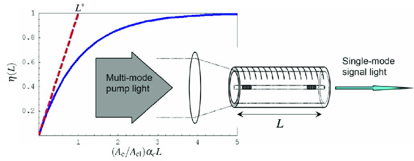
The inset in Fig. 1 shows a schematic presentation of a cladding-pumped fiber laser. The double-clad approach was pioneered by Snitzer and co-workers in the late 1980’s (see Ref. [5] and references therein) and the basic concept of the double-clad fiber laser is to facilitate conversion of multi-mode light into a single-mode beam of high quality. The pump light is corralled by the double-clad and while light propagates down the fiber, photons are absorbed and converted to stimulated emission by a rare-earth doped fiber core at the center of the inner cladding. Typically, the laser cavity is formed by inscribing Bragg reflectors in the fiber core.
Here, we focus on air-clad technology [6] which has greatly advanced the potential of double-clad fibers [7, 8, 9, 10, 11, 12]. The large index contrast between air and silica makes the cladding support pump light of very high numerical aperture [13], thus facilitating pumping by relatively cheap high-NA pump sources. For the corralled pump light, skew rays [14], or whispering gallery modes (WGMs), are well-known obstacles to efficient pump absorption since they do not have a significant overlap with the core. Such modes are particular inherent to cylinder symmetric fiber geometries, such as standard MCVD-fabricated fibers. The problem may be circumvented by breaking the high cylindrical symmetry and D-shaped cladding geometries [15] have become a standard approach to suppression of skew rays.
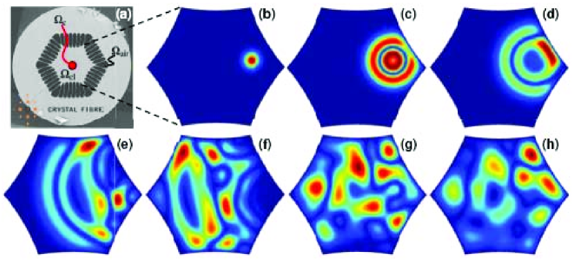
Pump absorption in air-clad fibers is typically very high and it has been speculated [16] that this is coursed by chaotic ray dynamics. Non-integrable air-clad geometries seem to be inherent to the fabrication method where the shapes of the air holes arise in an interplay and competition of e.g. the glass viscosity and glass-air surface tension. Fig. 2 illustrates one example of an air-clad fiber [10] which has a classically chaotic geometry with a convex boundary (from the point of view of the pump light) which will scatter incident waves in a highly non-deterministic way. Time-dependent finite-element simulations of a scalar wave equation in a corresponding confined geometry, panels (b) to (h), do indeed support this picture of chaotic wave dynamics. Indeed, the pump absorption observed in Ref. [10] is much stronger than for an equivalent circular geometry.
In this work we use finite-element simulations to show how the wave dynamics has fingerprints inherited from the classically chaotic geometry. In particular, we consider the statistics of the mode-overlap with the core and argue that air-clad fibers tend to be chaotic by nature in the case of sup-wavelength convex air-clad features.
2 Formalism
For simplicity we consider the simplified problem with a spatially homogeneous inner cladding region with dielectric function and a rare-earth doped fiber core region with dielectric function , see panel (a) in Fig. 2. The inner cladding may be defined by several air regions . The complex-valued dielectric function is then of the form
| (1) |
where for the rare-earth doped core so that absorption is a weak perturbation. In the following we consider temporal harmonic modes which are governed by the wave equation
| (2) |
where is the angular frequency and is the speed of light. For a fiber geometry, translational invariance along the fiber axis results in modes of the plane-wave form with the dispersion relation found by solving Eq. (2). Typically, the dispersion properties are obtained through numerical solutions of Eq. (2), but perturbation theory is another highly valuable tool in analyzing the consequences of minor perturbations such as variations in the dielectric function. For a fixed frequency, we apply standard first-order perturbation theory to predict the corresponding shift in the propagation constant ,
| (3) |
where is the group velocity which is mathematically introduced through the use of the chain rule [17].
3 Pump absorption
Obviously, a complex dielectric function as in Eq. (1) will for a fixed and real-valued frequency result in a complex valued propagation constant . The interpretation of the imaginary part as a damping becomes obvious when expecting the intensity where we have introduced the damping parameter . In the following we will consider the case where the imaginary part in Eq. (1) is a small perturbation to the real part, i.e. so that . From Eq. (3) we immediately get
| (4) |
where we have introduced the relative optical overlap with the core
| (5) |
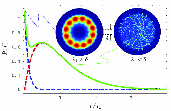
with being the displacement field. In the last equality of Eq. (4) we have approximated the group velocity by that in the homogenous core material, thus allowing for the introduction of the core material absorption parameter . The interpretation of Eq. (4) is straight forward; the absorption of a given mode is very intuitively given by of the core material weighted by the relative optical overlap of the mode with the core. Now, since the cladding diameter by far exceeds the wavelength of the light we will have a continuum of cladding states, even for typical low-NA air-clad fibers [18], so studying the characteristics of the individual modes is cumbersome. Instead it is common to quantify pump absorption by a single parameter, i.e. the pump absorption efficiency as indicated in Fig. 1
| (6) |
Here, is the distribution of attenuation coefficients while is the absorption efficiency for the individual mode for a length of propagation. In the second equality we have used the approximation in Eq. (4) and introduced the distribution of the overlap integrals defined by Eq. (5). With the form of Eq. (6) we have implicitly assumed a uniform excitation at the input facet of the fiber so that each mode has the same initial amplitude and initially carries the same power. Furthermore, mode mixing due to longitudinal non-uniformities, including bending, is obviously not taken into account. In that sense Eq. (6) gives a lower bound for the pump absorption efficiency.
A general evaluation of the integral of course requires that we know the distribution function in detail. However, the initial decay is easily found by expanding the square-bracket part of the integrand. This conveniently leaves us with a result in terms of the moments of the distribution function,
| (7) |
Obviously, the higher a mean value and the smaller a spread the more efficient a pump absorption for a given length . From Eq. (7) we may now easily estimate the critical length of fiber required to achieve an efficient conversion of the pump. From we get
| (8) |
demonstrating how fiber geometries with a large mean value will facilitate fiber lasers with a shorter laser cavity. In the following we will study chaotic means for enhancing the mean value and thus decreasing .
4 Chaos and the ergodic hypothesis
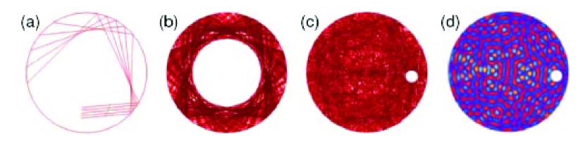
The term ’chaos’ is used in many contexts of mathematics and physics, but here it is used with reference to the wave dynamics in a confined geometry. Since the double clad structures that we are considering have dimensions much larger than the wavelength it is quite natural to illustrate the signatures of chaos by means of the classical ray dynamics that occurs if we consider geometrical optics. In Fig. 3 we illustrate the important difference between regular integrable geometries and their non-integrable chaotic counterparts. The circular geometry in panel (a) is an excellent example where (assuming total internal reflection) we may easily advance the rays in time, keeping in mind that the angle of reflection equals the angle of incidence. Panel (b) shows the corresponding whispering-gallery like ray pattern that results at a much later time. From a pump-absorption point of view the problem is of course that the rays do not visit the center of the geometry (where the absorbing core is typically located) and changing the initial conditions (by e.g. changing the angle of incidence) does not necessarily change this picture significantly. Panel (c) shows a non-integrable chaotic geometry where the inclusion of small circular scatterer completely changes the ray dynamics compared to panel (b) even though the two trajectory patterns originate from the same initial conditions. If we focus on the wave nature of light in classically chaotic geometries then chaos reveals itself in several ways including the ’scarred’ nature of the wave functions [19] as illustrated by the example in panel (d). As for the ray dynamics in panel (c) the wave functions also tend to explore the entire phase space rather than being of the whispering-gallery like nature seen in panel (b).
From a pump absorption point of view, chaos completely changes the distribution of overlaps. Assuming that the eigenfields are, on average, spatially fully homogenized, then Eq. (5) reduces to
| (9) |
where and are the areas of the core and cladding regions, respectively. In the following we use the definition . The above assumption corresponds to the ergodic limit where all modes visit all parts of the phase space equally. We then have so that and due to the simple properties of the Dirac delta function Eq. (6) is now easily evaluated with the result
| (10) |
showing a single-exponential behavior as illustrated in Fig. 1. Finally, Eq. (8) reduces to
| (11) |
which is the ultimate scaling which can be achieved for the absorption of the pump.
5 Overlap statistics
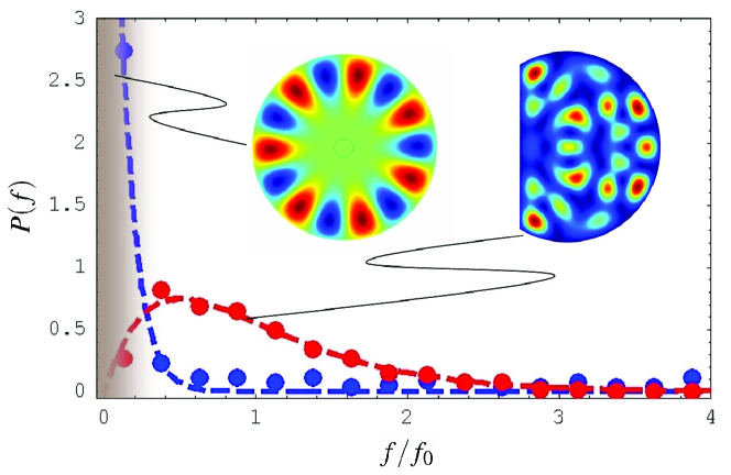
In the following we illustrate the difference between an integrable geometry and a chaotic geometry by comparing rods of glass in air with a circular and D-shaped cross section, respectively. We use a finite-element method (COMSOL Multiphysics) to calculate fully vectorial eigenmodes of Eq. (2) from which we evaluate Eq. (5) numerically. Grouping the data into bins of width we arrive at the histogram shown in Fig. 4. For simplicity we have considered and for the wavelength we have used with being the radius of the cladding. Furthermore, the core is placed in the center of the fiber and . Results for the circular case are shown in blue while the red results are for a corresponding D-shaped geometry. The dashed lines are numerical fits to the following normalized distribution functions
| (12) |
with the mean value used as fitting parameter. Fig. 4 is illustrating the close to exponential distribution in the case of the integrable geometry while for the chaotic geometry the weight is shifted to much larger values with a suppression of modes with a poor overlap. The insets show typical modes for the two geometries. For the circular geometry the peak in the distribution originates from WPGs which are suppressed in the D-shaped geometry where modes are of the ’scarred’ nature with an average overlap in agreement with the ergodic hypothesis. Obviously, in the context of the chaotic structure is superior to the integrable one as also emphasized previously in the literature [15, 20, 21, 22].
A quite natural question now arises; are air clad structures truly chaotic? As we shall see the answer to this inquiry depends a lot on the geometry into which the air holes are arranged. For the simulations in Fig. 2 we neglected the sub-micron silica bridges separating the sup-micron convex air-clad features. At first this appears reasonable if the bridges are sub-wavelength. However, one should not compare to the free-space wavelength (or for that sake), but one should rather consider the effective transverse wavelength which may exceed significantly. Projecting the problem onto the transverse cross section of the fiber we get
| (13) |
where is the effective index of mode . Now, let be a characteristic length scale for the air-clad features, such as the bridge width or the air-hole diameter. The modes may now be classified by comparing with ;
-
•
For the electromagnetic field effectively experiences a smooth boundary defined by the air clad and the wave dynamics may be integrable or chaotic depending on the effective shape of the corral.
-
•
For the field explores all the detailed features and in particular the convex air-clad boundary so that the wave dynamics turn chaotic.
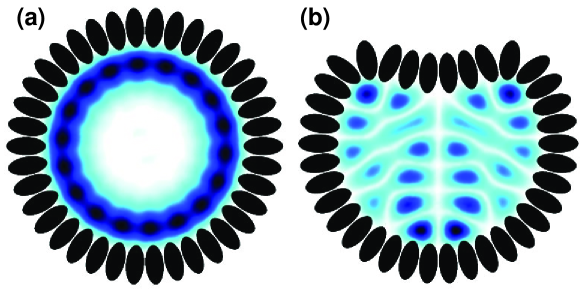
While the geometry in Fig. 2 is chaotic in both limits one can easily imagine more regular air-clad structures which will only be ’partly’ chaotic, i.e. low-NA modes will experience an integrable confinement geometry while high-NA modes will experience a chaotic geometry. Indeed, the insets in Fig. 5 illustrate this perfectly for a geometry very much resembling the over-all cylindrical symmetry of the air-clad structure employed in more recent works such as Ref. [23]. The air-clad structure consists of 27 air-holes distributed evenly in a cylindrical symmetry with radius . The modes are obtained by fully-vectorial finite-element solutions of Eq. (2) for a wavelength of . While a quantitative numerical simulation of the full statistics and the distribution function is cumbersome we imagine that the two classes of modes will give rise to a distribution function qualitatively interpolating the two limits in Eq. (12) as indicated schematically in Fig.5. The existence of skew rays and WPGs, represented by the exponential peak near , will eventually suppress the average value below the ergodic limit given by thus compromising the pump-absorption efficiency and the critical absorption length . Deforming the ring-shaped air-clad slightly, or introducing an additional air hole as in panel (c) or (d) of Fig. 3, would suppress the exponential peak at and restore the distribution function with characteristic of chaotic wave dynamics. Fig. 6 illustrates how WPGs may be suppressed by constructing the air-clad in a D-shaped fashion.
6 Conclusion
We have discussed wave chaos in the context of the pump-absorption efficiency in air-clad fibers which are now being widely used for high-power cladding-pumped fiber lasers. Starting from the wave equation we rigorously derive a result for which in the ergodic limit scales as , where and are the areas of the rare-earth doped core and the cladding, respectively. While air-clad structures supporting sup-wavelength convex air-clad features will promote chaotic dynamics we also show how this may be jeopardized by whispering-gallery modes in air-clad structures resembling an overall cylindrical symmetry. In the absence of mode-mixing mechanisms, highly symmetric air-clad structures may thus suppress the pump-absorption efficiency below the ergodic scaling law.
Acknowledgements
Publication of this work is financially supported by the Danish Council for Strategic Research through the Strategic Program for Young Researchers (grant no: 2117-05-0037). J. Broeng, A. Petersson, M. D. Nielsen, J. Riis Folkenberg, P. M. W. Skovgaard, C. Jakobsen, H. Simonsen, and J. Limpert are acknowledged for sharing their insight in experiments, theory, design, and fabrication of air clad fibers.