Low-loss grating for coupling to a high-finesse cavity
A. Bunkowski, O. Burmeister, P. Beyersdorf, K. Danzmann, and R. Schnabel
Max-Planck-Institut für Gravitationsphysik
(Albert-Einstein-Institut), and Institut für Atom- und
Molekülphysik,
Universität Hannover, Callinstr. 38, 30167
Hannover, Germany
T. Clausnitzer, E.-B. Kley, and A. Tünnermann
Institut für angewandte Physik, Friedrich-Schiller-Universität Jena, Max-Wien-Platz 1, 07743 Jena, Germany
Abstract
A concept for a low loss all-reflective cavity coupler is experimentally demonstrated at a wavelength of 1064 nm. A 1450 nm period dielectric reflection grating with a diffraction efficiency of 0.58 % in the -1st order is used in 2nd order Littrow configuration as a coupler to form a cavity with a finesse of 400. The application of such reflective low-loss cavity couplers in future generations of gravitational-wave detectors as well as some implementation issues are discussed.
OCIS codes: 050.1950, 120.3180, 230.1360.
An international network of first-generation, kilometer-scale, earth-bound laser-interferometric gravitational-wave (GW) detectors consisting of LIGO [1, 2], GEO 600 [2], TAMA 300 [3], and VIRGO [4] is currently moving from the commissioning phase to the long-term data-taking operational phase. These detectors are Michelson interferometers. Power recycling and arm cavities are two techniques being used to increase the laser power in the interferometer and hence the detector sensitivity. Both techniques utilize cavities to which laser light is coupled via a partially transmitting mirror. For first generation detectors the light power inside the interferometer will be in the order of 10 kW at a wavelength of 1064 nm. To increase the detection sensitivity even further future GW interferometers will use light power in the order of MW for which heating effects in the transmissive elements become an issue. Power absorption in the substrates leads to thermal lensing and also to deformation of the optical surface. These distortions will limit the circulating power below the level which is necessary to optimize quantum noise. To reduce thermal noise cryogenic techniques for the main optics are very likely to be used in third generation GW detectors. Absorbed heat in the substrates will worsen the cooling efforts of the optical elements. To avoid heating in the substrate reflective grating beam splitters can be used instead of partially transmissive mirrors and beam splitters [5]. An additional advantage of all reflective optics within GW detectors is the elimination of the constraint that the substrate materials be optically transparent. Considering opaque substrate materials with superior mechanical properties allows lowering the thermal noise in the detector.
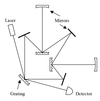
In proof-of-principle experiments Sun and Byer [6] demonstrated a Michelson and a Sagnac interferometers based on all-reflective elements. They also demonstrated a Fabry-Perot coupler concept that is based on high diffraction efficiency gratings in 1st order Littrow configuration. Drever pointed out that low diffraction efficiency gratings could also be used as cavity couplers and argued that the overall losses should be lower than in high diffraction efficiency elements. An all-reflective interferometer configuration which avoids the use of a 50/50 beamsplitter and uses low diffraction efficiency gratings and mirrors as the only major optical elements as schematically depicted in figure 1 was proposed [5]. But to our knowledge no experimental realization of interferometers utilizing low diffraction gratings has been reported so far.
In this letter we report on the design of a low-loss diffraction grating with a diffraction efficiency of less than 1 % and on the experimental realization of a high-finesse linear cavity using the grating as a coupler.
For a laser beam of wavelength incident on a reflection grating, the output angle of the th diffracted order is given by the well known grating equation
| (1) |
where is the incidence angle and is the grating period. If used in 1st order Littrow configuration a reflection grating can be used as a cavity coupler[6]; the reflected (0th order) beam is used to couple into the resonator. The finesse of such a resonator is limited by the maximum diffraction efficiency of the first order of the grating. However if used in 2nd order Littrow configuration, as shown in figure 2 the diffracted (-1st) order is used to couple to the cavity. Then the maximum reflectivity R0 of the grating under normal incidence is the limiting factor for the finesse of the cavity.
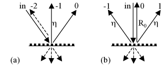
Standard coating techniques can routinely produce multi-layers with a reflectivity greater than 99.98 %. This value is to be compared with routinely produced maximum diffraction efficiencies of about 95 % [7]. To our knowledge the highest value ever reported so far is also not greater than 99 %[9]. Therefore the 2nd order Littrow configuration is the appropriate choice for efficient low-loss coupling to a linear resonator.
Every diffraction order that is allowed by the grating equation will contain some light power. To reduce overall losses in the device the grating period should be chosen in a way that only the diffraction orders that are going to be used are allowed by the grating equation. Only the orders for normal incidence are needed in our case which suggests
| (2) |
A common way of manufacturing high efficiency dielectric reflection gratings is to etch a periodic structure into the top layer of a dielectric multilayer stack as it is done for the gratings used in high-power chirped-pulse amplification [8]. For the low diffraction efficiency grating needed for our application we used a different approach. We first etched the grating into a substrate and then overcoated it so that the dielectric layers effectively form a volume grating as can be seen in figure 3. A shallow binary structure with a depth of 40-50 nm, a ridge width of 840 nm and a period of nm was generated by electron beam lithography and reactive ion beam etching on top of a fused silica substrate. The applied multilayer stack was composed of 32 alternating layers of silica (SiO2) and tantalum pentoxide (Ta2O5). The diffraction efficiency for 1064 nm light with a polarization plane parallel to the grating grooves and perpendicular to the plane of incidence (-polarization) was measured to be .
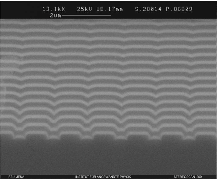
Figure 4 shows the experimental setup for the all-reflective Fabry-Perot cavity. A high reflective (HR) mirror with a radius of curvature of 1.5 m mounted on a piezoelectric transducer (PZT) to allow for cavity length control was placed parallel to the grating surface at a distance of 43 cm. An -polarized beam of 50 mW from a 1.3 W, 1064 nm diode pumped Nd:YAG laser was used. The angle of incidence corresponded to second order Littrow configuration The circulating and reflected power from the cavity were observed using the leakage from the high reflector and from the 0th order of the grating respectively.
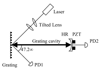
High circulating powers inside the cavity also demands good mode matching of input beam and cavity mode. Note that our grating couples modes at different angles of incident which changes the ratio of horizontal an vertical mode widths. The following relation holds for the horizontal width of the beam
| (3) |
where and refer to the incoming and the diffracted beam respectively. For our setup an input beam with an elliptical profile having a horizontal width of 1.47 times the vertical width produced the desired round beam profile in the diffracted beam. The profile is generated by a pair of lenses from which one lens was tilted horizontally to have different focal lengths for the - and -directions.
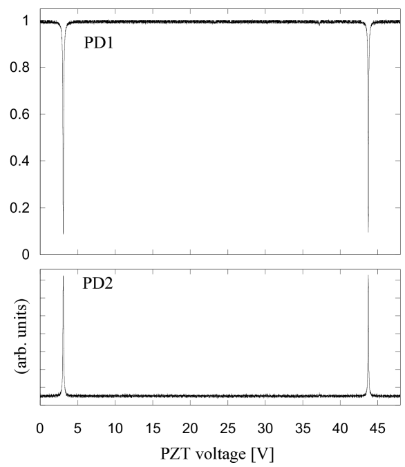
Figure 5 shows the transmission and reflection interference fringes for the cavity with a measured cavity finesse of . More than 99 % of the power was measured to be in the TEM00 mode indicating excellent mode matching. With the measured value of the finesse and the known reflectance of the HR-mirror one can calculate the overall losses which are defined by , where is the the reflectance for normal incidence. We find . Losses are due to transmitted orders and scattered light.
The partially transmissive mirrors conventionally used for coupling to a linear Fabry-Perot cavity can be considered as 2-port devices with simple phase relations between the two ports. The input coupler introduced here, however, is a 3-port device. Light entering one port will always couple to all three ports. The phase relations of the light in the three different ports are more complex than in a 2-port device. They depend on the diffraction efficiencies for the different orders and can be calculated with a scattering matrix formalism [10]. Due to the additional port new GW detector topologies can be accomplished. The scheme shown in figure 1 for example uses two linear grating cavities in the arms. On resonance these cavities will retro-reflect most of the power incident onto the grating while the signal sidebands generated in the arms will be split equally between the two output ports of the cavity. Therefore power and signal are taking different paths in the interferometer. A detailed analysis of the phases of the three ports of the coupler as well as their effects on the properties of the proposed interferometer is in preparation and will be presented in a forthcoming paper.
In conclusion we have experimentally demonstrated that a low efficiency grating can be used as a cavity input coupler with low loss. A cavity with a finesse of 400 was constructed far exceeding the best finesse values for an all-reflective cavity that had been previously reported. In a next step we will optimize design and manufacturing process of the gratings to produce gratings with even lower diffraction efficiency and overall losses. These gratings will have high potential to be implemented in future GW detector configurations.
This research was supported by the Deutsche Forschungsgemeinschaft within the Sonderforschungsbereich TR7.
References
- [1] A. Abramovici, W. E. Althouse, R. W. P. Drever, Y. Gürsel, S. Kawamura, F. J. Raab, D. Shoemaker. L. Sievers, R. E. Spero, K. S. Thorne, R. E. Vogt, R. Weiss, S. E. Whitcomb, and M. E. Zucker, ”LIGO: The Laser Interferometer Gravitational-Wave Observatory,” Science 256, 325 (1992).
- [2] B. Abbott et al., ”Detector description and performance for the first coincidence observations between LIGO and GEO,” Nuclear Instruments and Methods in Physics Research A bf517, 154 (2004).
- [3] M. Ando et al., ”Stable Operation of a 300-m Laser Interferometer with Sufficient Sensitivity to Detect Gravitational-Wave Events within Our Galaxy,” Phys. Rev. Lett. 86, 3950 (2001).
- [4] F. Acernese et al., ”Status of VIRGO,” Class. Quantum Grav. 21, 709 (2004).
- [5] R. W. P. Drever, ”Concepts for Extending the Ultimate Sensitivity of Interferometric Gravitational Wave Detectors Using Non-Transmissive Optics with Diffractive or Holographic Coupling,” in Proceedings of the Seventh Marcel Grossman Meeting on General Relativity, M. Keiser and R.T. Jantzen, eds. (World Scientific, Singapore, 1995).
- [6] K.-X. Sun and R.L. Byer, ”All-reflective Michelson, Sagnac, and Fabry-Perot interferometers based on grating beam splitters,” Opt. Lett. 23 567 (1997).
- [7] T. Clausnitzer, J. Limpert, K. Zöllner, H. Zellmer, H.-J. Fuchs, E.-B. Kley, A. Tünnermann, M. Jupé, and D. Ristau, ”Highly efficient transmission gratings in fused silica for CPA systems,” Appl. Opt. 42, 6934 (2003).
- [8] B. W. Shore, M. D. Perry, J. A. Britten, R. D. Boyd, M. D. Feit, H. T. Nguyen, R. Chow, G. E. Loomis, and Lifeng Li, ”Design of high-efficiency dielectric reflection gratings,” J. Opt. Soc. Am. A. 14, 1124 (1997).
- [9] J. A. Britten, S. J. Bryan, L. J. Summers, H. T. Nguyen, B. W. Shore, and O. Lyngnes, ”Large Aperture, High-Efficiency Multilayer Dielectric Reflection Gratings”, in Proceedings of IEEE Conference on Lasers and Electro-Optics (Opt. Soc. America, Washington, 2002) pp.CPDB7-1-4.
- [10] A. Siegman, Lasers (University Science Books, Sausalito, 1986).