Electron-phonon and
electron-electron interactions
in organic field effect transistors
Abstract
Recent experiments have demonstrated that the performances of organic FETs strongly depend on the dielectric properties of the gate insulator. In particular, it has been shown that the temperature dependence of the mobility evolves from a metallic-like to an insulating behavior upon increasing the dielectric constant of the gate material. This phenomenon can be explained in terms of the formation of small polarons, due to the polar interaction of the charge carriers with the phonons at the organic/dielectric interface. Building on this model, the possible consequences of the Coulomb repulsion between the carriers at high concentrations are analyzed.
keywords:
1 Introduction
In organic field effect transistors (FETs), charges move in a conducting layer located at the interface between an organic crystal and a gate insulator. Commonly used gate insulators such as SiO2 or Al2O3 are polar materials. When an electron moves in the vicinity of such materials, it induces a long-range polarization that modifies its physical properties, forming a polaron. This mechanism is well known in inorganic semiconductor heterostructures such as GaAs/AlAs.[1] There, however, due to the weak polarizabilities and to the extremely low band masses, the polar coupling only causes a small renormalization of the electronic properties.
In organic FETs, there are two important differences that can eventually lead to much more dramatic effects. The first is that organic crystals have very narrow bandwidths, due to the weak Van der Waals bonding between the molecules. The second is that one can use gate insulators where the static () and high frequency () dielectric constants have a large difference in magnitude, i.e. that are much more polarizable than GaAs.
Indeed, recent experiments performed on rubrene single crystal FETs have shown that the charge carrier mobility at room temperature decreases upon increasing the dielectric constant of the gate material.[2] At the same time, the temperature dependence of the mobility evolves from a metallic-like to an insulating-like behavior, [3] which gives strong support to the relevance of polaron formation.
In this work we present a theoretical framework that consistently explains the observed experimental behavior. The model which describes the interaction of the charge carriers with the ionic polarization at the interface, as well as the basic results concerning the formation of small polarons, are presented in Section 2. The temperature dependence of the polaronic hopping mobility is calculated in Section 3, where we briefly discuss the experimental results of Ref. [3]. The possible relevance of the long-range Coulomb repulsion between the carriers at sufficiently high concentrations is discussed theoretically in Section 4.
2 Polaron formation
The interaction between the carriers and the polar interface is described by the following Fröhlich Hamiltonian [1, 4, 5]
| (1) | |||||
where , , , are respectively the creation and annihilation operators for carriers, whose dispersion is , and for optical phonons of frequency . The electron-phonon matrix element is defined as
| (2) |
where is the lattice spacing in the organic crystal, is the total surface and is the mean distance between the carriers and the interface. The strength of the electron-phonon coupling is controlled by the dimensionless parameter
| (3) |
which is a combination of the dielectric constant of the organic crystal () and those of the gate material.
The above matrix element was derived in the long-wavelength limit. A cut-off at short distances (at ) is needed in principle to account for the discrete nature of the molecular crystal. [7, 8] However, the finite distance already acts as a short-distance cut-off: is exponentially reduced at the Brillouin zone boundaries for , in which case we can use Eq. (2) for all practical purposes. A prescription to deal with discrete lattice effects for is proposed in the Appendix.
Due the interaction term in Eq. (1), the electrons get “dressed” by the ionic polarization of the gate material. If the interaction is sufficiently strong, the carriers become self-trapped on individual (or few) organic molecules, forming small polarons, and hopping-like transport can set in.
The polaron energy in the strong coupling regime is given by .[6] Integrating this expression over the whole reciprocal space leads to the simple result
| (4) |
The polaron energy turns out to be independent on the phonon frequency , and therefore depends on the particular gate dielectric only through the parameter . It should be noted that the exponential decay of the matrix element does not imply an analogous decay of the polaron energy with distance, but rather yields a behaviour as can be seen from the above result.
The condition for the formation of a small polaron roughly corresponds to , where is the nearest-neighbor transfer integral. According to the result Eq. (4), taking as representative for organic crystals and assuming a typical value ( in rubrene), we see that the formation of small polarons is expected as soon as . The physical parameters characterizing the different dielectrics used in Refs. [2, 3] are reported in Table I.
| Ta2O5 | 25 | 4.4 | 200-1000 | 0.099 |
| Al2O3 | 9.4 | 3 | 400-900 | 0.086 |
| SiO2 | 3.9 | 2.1 | 400-1240 | 0.051 |
| parylene | 2.9 | 2.56 | 500-1800 | 0.010 |
| Si3N4 | 5 - 34 | 4.2 | - | 0.014-0.11 |
3 Activated mobility
The mobility of small polarons in the hopping regime can be evaluated by mapping the problem onto a two-site cluster.[9] In this reduced model, the electrons interact with the long-range polarization field created by the interface optical phonons via an appropriate collective coordinate . In the adiabatic regime, where the lattice motion is much slower than the electrons, the electronic degrees of freedom can be integrated out leading to a double-well potential landscape for the coordinate . The mobility in the hopping regime can be expressed using standard techniques as
| (5) |
where the Kramers rate is determined by the frequency of oscillation around the minima of the potential-well, 111The prefactor in Eq. (5) is affected by several microscopic parameters such as the lattice geometry, the interaction with multiple phonon modes, the polaron size, dynamical friction, which can sensibly modify this result. and the activation energy corresponds to the height of the barrier. 222In the above derivation we have implicitly assumed the adiabatic regime, which is valid when . A formula similar to Eq. (5) hods true in the opposite anti-adiabatic limit. In that case the activation barrier is , and the prefactor must be replaced by . It is related to the polaron energy defined in Eq. (4) by
| (6) |
Here is a parameter which depends on the shape of the interaction matrix element:[6]
| (7) |
The second equality has been obtained using Eq. (2), which is valid for . Note that for a local interaction (Holstein model, ), from Eq. (7) one recovers . A calculation of including the effects of the discrete lattice is presented in the Appendix.
The temperature dependence of the mobility has been measured in Ref.[3] in devices using the different gate dielectrics listed in Table I. In practice, the measured includes contributions from other scattering mechanisms, such as the coupling with molecular vibrations inside the organic crystal. These are entirely responsible for the mobility observed in devices in which the gate insulator is vacuum, and can be subtracted out from the raw data via the Matthiessen rule .
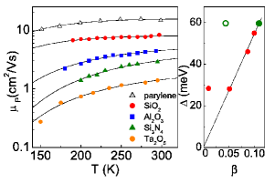
In Fig. 1 we report the polaronic part of the mobility, obtained with the above described procedure. Upon increasing the dielectric constant of the gate insulator (which amounts to increasing ), the temperature dependence evolves towards an insulating-like behavior that can be fitted reasonably well with Eq. (5). The values of the activation barrier extracted from the fits are reported in the right panel. Despite the rather limited experimental temperature range, is a linear function of for the devices with the strongest polarizabilities (SiO2, Al2O3, Ta2O5), as expected from Eqs. (4) and (6). Furthermore, from the slope of vs , a typical distance between the carriers and the interface can be estimated, which is comparable with the lateral size of a rubrene molecule. Note that the effect of [cf. Eq. (7)] was not considered in Ref.[3], which led to a higher estimate for this distance ().
4 Electron-electron interactions
Having established that the electron-phonon interactions can be tuned by changing the polarizability of the gate material, we now investigate the possibility of controlling the Coulomb interactions between electrons. It is clear that these are negligible at low carrier concentrations, i.e. in the linear regime of the vs. curves, where the conducticity is directly proportional to the carrier density (see e.g. Fig. 1 in Ref. [3]).
However, especially in the devices with strongly polarizable gate dielectrics, a sizable carrier density can in principle be induced at the highest attainable gate voltages. For example, in a device with a Ta2O5 layer of thickness , a concentration holes per rubrene molecule can be reached at . At such density, the effects of the electrostatic repulsion between the carriers cannot be neglected a priori. Here we propose a simple theoretical framework to describe their possible consequences on the device performances.
Let us start by observing that the Coulomb interaction between two electrons in proximity to a polarizable dielectric is screened by the image charges as
| (8) |
In the following we shall assume that the average interelectron distance is larger than the distance between the electrons and the interface, so that Eq. (8) can be replaced by its asymptotic expression .
In a system of interacting electrons, each charge feels instantaneously the sum of the repulsive potentials of the others. Dynamical screening is unlikely in the regime under study, where the motion of the charge carriers is hindered by the formation of small polarons. For the same reason, if we focus on a given particle while it hops to its neighboring site, the relaxation of the remaining electrons can be neglected to a first approximation: the collective rearrangement of charges necessarily implies several hopping processes, and therefore occurs on a much longer time scale than the individual hopping event under consideration.
From the above arguments, if the interacting fluid is initially at (or sufficiently close to) equilibrium, it can be expected that moving a given particle from a site to its nearest neighbor will have a net energy cost , that adds to the polaronic hopping barrier . In fact, such an energy cost can be easily included in the two-site model presented in the preceding Section. It leads to an increased value of the activation barrier , which eventually reduces the carrier mobility compared to the result Eq. (5) for independent polarons. 333This expression is valid for . More generally, the activation barrier in a biased double-well potential is given by . The mobility in the presence of electron-electron interactions can thus be expressed as:
| (9) |
To get an order of magnitude estimate of this effect, we replace the actual (uniform) distribution of polarons by a triangular array of point charges at the same density. This approximation is expected to be qualitatively correct for the following reasons: first of all, it is known[10] that the local correlations in an interacting charged liquid are very similar to the ones of a crystallized state. On the other hand, due to the long-range nature of the interaction potential Eq. (8), the result for should depend only weakly on the details of the charge distribution. Finally, the proposed lattice approximation enforces in a simple way the absence of relaxation of the electron fluid mentioned above.
The potential energy of a given particle in a lattice can be expanded for small displacements around its equilibrium position as:
| (10) |
Here is the radius of the Wigner-Seitz disk , which is proportional to the average electron-electron distance, and is a geometrical factor characterizing the triangular lattice. In the present approximation, the additional energy cost for hopping between molecules induced by the electrostatic repulsion between the carriers is simply given by . Defining the carrier concentration according to leads to
| (11) |
in the case of Ta2O5. For , we obtain a value that is consistently smaller than the polaronic barrier . According to Eq. (9) the Coulomb interactions between the carriers can reduce the mobility by at room temperature, and even more at lower temperature. Such behavior should be clearly visible as a bending down in the vs curves at the highest attainable values of the gate voltage. 444It can be argued that such high values of can modify the charge distribution along , therefore modifying the value of the activation barrier according to Eqs. (4), (6) and (7). [5] This effect, however, should not play a dominant role if the polarons are already “small”. [11, 12]
Note that the concentration that can be reached at a given voltage is proportional to the dielectric constant . As a result, for devices of equal thickness, the maximum value of increases with as . The observation of Coulomb interaction effects is therefore more likely in FETs with highly polarizable gate materials.
5 Concluding remarks
In this paper we have reviewed a model which describes the interaction of the charge carriers with the interface phonons in single crystal organic FETs. Our analysis demonstrates that the electron-phonon interaction can be tuned by changing the dielectric polarizability of the gate material. This model consistently explains the evolution of the carrier mobility from a metallic-like to an insulating-like behavior that has been recently observed in Refs. [2, 3]: increasing the dielectric polarizability of the gate insulator results in a crossover from the weak to the strong coupling regime where the carriers form small polarons, which gives rise to a thermally activated mobility. Building on this model, the possibility of revealing experimentally the effects of the long range Coulomb repulsion between the carriers at high concentrations has been analyzed.
In conclusion, although the main interest in organic FETs comes from their potential applications in ”plastic electronics”, the opportunity of tuning several parameters such as the carrier density, the electron-phonon and possibly the electron-electron interactions, makes them an ideal playground for fundamental physics.
Appendix A On the lattice cut-off of the electron-phonon interaction.
Any linear electron-phonon interaction of the form of Eq. (1) can be transformed to real space as
| (12) |
where , being the lattice sites. A simple prescription to define a discrete version of the Fröhlich model, appropriate on a lattice, is to introduce a short-range cut-off of the order of the lattice spacing, which defines a new potential . The correct periodicity of the matrix element on the Brillouin zone can then be restored by setting
| (13) |
It is clear that the new matrix element obeys with any reciprocal lattice vector, which is not the case for of Eq. (2). By taking the continuous limit and letting the cutoff one recovers .
Fröhlich interaction in 3D. The essence of the Fröhlich model is the interaction of a charge (monopole) with a field of dipoles in an ionic material (+ and - ions). Correspondingly, the usual polar electron-phonon interaction in 3 dimensions, , scales in real space as , namely
| (14) |
The simplest way to introduce a lattice cut-off is to flatten off the potential at short range by setting . Alternatively, one can define
| (15) |
with of the order of the lattice spacing . Transforming back to reciprocal space leads to the familiar Yukawa form.
A physically sound choice for the cutoff length in Eq. (15) is to set equal to the energy of self-interaction of a uniform charge distributed on a cube of side ,[7] which yields . However, the polarizability of the medium at short distances is certainly less than what is predicted by continuum theory, so that the above estimate should be considered as a lower bound for .
Note that the potential Eq. (15) looks essentially similar to the one proposed in Ref. [8] to describe the interaction with the apical oxygens in the superconducting cuprates, except for the different decay at long distances, reflecting a different physical origin of the interaction (in that case, ). As for the short distance cut-off, the authors of Ref. [8] use .
Polar interaction at interfaces. The interaction term of Eq. (2), that we rewrite here as , already has a short distance cut-off determined by the distance from the interface. Indeed, transforming to real space yields the following Hypergeometric function
| (16) |
that scales as for large , but tends to a constant for . Again, a lattice cut-off can be introduced in this expression either by flattening off the local term or by replacing .
As a final remark, to avoid dealing with the special function , a simpler model can be introduced that reproduces both its asymptotic limits (but slightly underestimates the polaron energy). It reads
| (17) |
where and .
The polaron energy in this model can be evaluated in real space as . Performing the discrete sum on a square lattice in the case gives a result which is about smaller than the result of the continuous approximation. On the other hand, the value of the parameter that determines the activation barrier increases by almost a factor , leading to an overall enhancement of the barrier. Although these numbers are quite sensitive to the choice of the cut-off prescription, they confirm that the continuous approximation used in the text is reasonably accurate for .
References
- [1] N. Mori, T. Ando, Phys. Rev. B 40, 6175 (1989)
- [2] A. F. Stassen, R. W. I. de Boer, N. N. Iosad, A. F. Morpurgo, Appl. Phys. Lett. 85, 3899 (2004)
- [3] I. N. Hulea et al., Nature Materials 5, 982 (2006)
- [4] J. Sak, Phys. Rev. B 6, 3981 (1972)
- [5] N. Kirova, M. N. Bussac, Phys. Rev. B 68, 235312 (2003)
- [6] G. D. Mahan, Many-Particle Physics, 2nd ed. (Plenum Press, New York, 1990)
- [7] Y. Lépine, J. Phys. Cond. Matter 6, 6611 (1994)
- [8] A. S. Alexandrov and P. E. Kornilovitch, Phys. Rev. Lett. 82, 807 (1999)
- [9] I. G. Lang, Yu. A. Firsov, Sov. Phys. Solid State 9, 2701 (1968)
- [10] N. Itoh, S. Ichimaru, S. Nagano, Phys. Rev. B 17, 2862 (1978)
- [11] Y. Iwasa, talk at the 2007 CERC Workshop, Tokyo May 2007
- [12] S. Fratini, H. Xie, I. N. Hulea, S. Ciuchi, and A. F. Morpurgo, in preparation.