Experiments on multidimensional solitons
1 Dimensional Aspects of Soliton Experiments in Bose-Einstein Condensates
The experimental work on solitons in BECs during the past decade has been extremely important in two respects. First, experiments have shown unambiguously that solitons and related nonlinear waves do exist in BECs. This was disputed at the time when the first experiments were performed in 1999 Burger1999a ; Denschlag2000a and may still be found surprising given that we are dealing with a quantum many-body system driven towards strongly non-equilibrium dynamics. Second, the experiments have inspired theoretical work in many directions. A particular example is the work on solitary waves in dimensional crossovers induced by trapping potentials that restrict the geometry, as discussed in Chap. Va.
A ubiquitous feature in all of the experimental realizations of solitons so far is the three-dimensional nature of experimental set-ups, which can never be completely neglected in the interpretation of the results obtained. In this respect almost all of the experimental work discussed in this book falls into the wider area of “multidimensional solitons.” In order to avoid the duplication of discussions led in other chapters, we chose to narrow the scope of this chapter to discuss mainly solitary waves with a genuinely multidimensional structure. We therefore restrict the discussion to experimental studies of the creation and dynamics of vortex rings in experiments at JILA Anderson2001a and Harvard Dutton2001a ; ginsberg05 . In particular, we completely omit the vast body of experimental work on line vortices and the related baby-skyrmions, i.e., vortices with filled cores Matthews1999b ; Anderson2000a ), as these will be covered in Chap. VI.
We also completely omit the experiments on bright solitons, and the first planar dark soliton experiments Burger1999a ; Denschlag2000a that were primarily concerned with soliton observation and propagation in BECs rather than dynamical instabilities and soliton decay. Detailed reviews of these experiments can be found in Chap. II and Chap. III, respectively.
2 Preparation of non-equilibrium BECs
None of the solitons and nonlinear waves discussed in this chapter are ground states. Rather, they are defects in the background density of the BEC. In order to facilitate the generation of such defects, the condensate is brought into an unstable or genuinely time-dependent dynamical state, such as a planar dark soliton in a single-component condensate. More stable multi-dimensional solitons can then form spontaneously as the decay product of an unstable initial state. In particular, vortex rings have been created by decay of moving or stationary planar dark solitons. The planar solitons themselves have been created by density engineering, which will be discussed below, by phase engineering, as discussed in Chap. III, or by a combination of both, which may be called quantum state engineering. Two different realizations of quantum state engineering have been proposed in Refs. Williams1999c ; carr01b .
2.1 Dark Soliton Quantum State Engineering
The method used at JILA to create planar dark solitons Ch3 in BECs is an example of quantum state engineering that manipulates both the BEC density and phase Anderson2001a . The technique relies on the ability to place a BEC into a superposition of two spatially overlapped components, where both the relative quantum phase and the amplitudes of the superposition components can be engineered to have a desired variation across the BEC Williams1999c . For the JILA experiments with 87Rb, a BEC has phase-coherent components created from the internal hyperfine atomic states and . The two components are coupled with a precisely engineered two-photon microwave field, enabling the overall superposition to be manipulated. To visualize this, let be a state vector which represents the spatial and temporal variations of the two-component BEC. Then the superposition takes the form
where, , , , and are real scalars which depend on time and space. Then is the number density of the component and is the relative phase. Two-component phase and density manipulation requires control of , , and in order to produce a final engineered superposition. Once the desired superposition is created, the microwave coupling drive is removed.
In the JILA experiment, the two atomic states effectively shared a potential well in all spatial coordinates. The two components also have nearly identical intra- and inter-component scattering lengths. Thus the sum remained approximately constant in space and time during microwave-induced internal state conversion, i.e., the total atomic density of the BEC did not significantly change, regardless of the spatial structure of the superposition. For example, if is constant across the BEC, and for and for , where labels the vertical spatial direction, there will be a phase jump across the plane of the part of the BEC made up of atoms. This phase jump corresponds to the phase jump across a horizontal dark soliton nodal plane.
With these general concepts, planar dark solitons were created in a nearly spherical potential with a mean trapping frequency of Hz and at temperatures of nK, or . With an initial BEC made entirely of atoms in state , a two-photon microwave field coupled the two atomic states inducing transitions while a laser-induced AC Stark shift altered the detuning of the microwave field from the atomic resonance. The beam was modulated across the BEC such that the coherent atomic transitions on opposite sides of the BEC were driven out of phase, resulting in a relative phase of between the two halves of the component- BEC. Additionally, transfer of atoms from to at the center of the BEC atom cloud was suppressed. Engineered superpositions of a dark soliton state in component and uniform-phase states of component were thus created. More precisely, a filled dark soliton was created in component , with atoms in component occupying the dark soliton nodal plane in , since the total BEC atomic density remained approximately constant in time and space. The dark soliton remained dynamically stable as long as the component- “filling” remained intact. To study planar dark soliton dynamical instabilities, including observations of soliton decay into vortex rings, the atoms were first removed with a short blast of a laser beam tuned to an electronic transition of the atoms. The subsequent observations will be described in Sec. 3.
The JILA state-engineering technique represents a general method for creating topological states, as described by Williams and Holland Williams1999c . For example, the two-component engineering technique was also used to create vortices in BECs Matthews1999b , and prior experimental results may be interpreted in terms of the creation of a vertical stack of filled horizontal dark solitons in a single BEC Matthews1999a . Additional details and references regarding this technique, and results of other experiments may be found in the experimental portion of Chap. IX of this volume, and in the references cited above.
2.2 Density Engineering by Slow Light
The method used in the lab of Lene Hau at Harvard to create nonlinear waves Dutton2001a ; ginsberg05 may be described as density engineering of the BEC. There are two stages in the process. First, a density depletion of the size scale of a couple of micrometers, or several healing lengths, is created on a microsecond timescale. In the next stage, the condensate reacts on the millisecond time scale by developing shock waves which shed soliton wave fronts. Here we describe the creation of the initial density depletions.
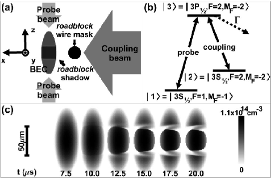
The scheme for creating density depletions is based on the method of ultra-slow light pulse propagation by electromagnetically induced transparency (EIT) boller91prl-EIT ; field91prl-EIT and an extension thereof termed roadblock for light Hau1999a ; Liu2001a . The experiments work with a rather large BEC of 1.5 to a few million 23Na atoms. The effect of EIT makes use of the level structure of 23Na and involves mainly the three states labeled , , and , in Fig. 1b, where is the ground state. A laser pulse tuned exactly on the transition (labeled “probe”) would not be able to propagate in a BEC of atoms in the state. The medium would absorb all the photons and appear opaque. If, however, the levels and are coupled by another laser field, the transition line splits into two lines and photons cannot be absorbed at the original transition frequency due to interference of the transition amplitudes. This effect is called EIT because the medium becomes transparent at the original transition frequency. Another consequence of this scenario is that the index of refraction varies strongly around the EIT frequency. This, in turn, leads to a greatly reduced group velocity which is indirectly proportional to the frequency gradient of . In this way the speed of light was reduced to a group velocity of 17 m/s Hau1999a ; dutton04 .
The reduction of the group velocity of light leads to a compression of light pulses in space by the same factor. In this way, a few microsecond long laser pulse of a kilometer length in vacuum is compressed to about 50m, at which point it is completely contained in the BEC. When the coupling laser is turned off abruptly at this point, light propagation stops completely and the energy and phase of the probe beam are stored in the condensate in the form of atoms in the state. By turning the coupling beam back on after a time window of the order of microseconds, the light pulse can be re-released coherently Liu2001a .
The idea behind the “light roadblock” is to transfer the above described technique of stopping light from the temporal to the spatial domain. The coupling beam does not illuminate the entire BEC cloud because part of it is shaded by means of a razor blade Dutton2001a or a wire mask ginsberg05 . Figure 1(a) shows a schematic of the experimental set-up of a double roadblock with a wire mask and two slow-light probe beams from Ref. ginsberg05 .
As the slow light pulse reaches the edge of the shadowed region of the BEC, the group velocity is reduced further, which in turn compresses the pulse further. At the size scale of a few microns, the stopped light transfers atoms from state into state . Since the atoms in state carry a photon-induced recoil momentum, they are ejected out of the condensate and leave within 1 ms without contributing much to the dynamics of the BEC of atoms in state . Figure 2 illustrates this point clearly in simulations of the dynamics in a coupled GPE model. The evolution of the density of state atoms during the slow-light propagation in the case of a double road block is shown in Fig. 1(c).
3 Decay Dynamics and Formation of Multidimensional Solitons
3.1 Quantum Shock Wave Dynamics and Soliton Shedding
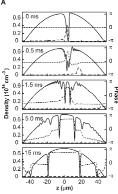
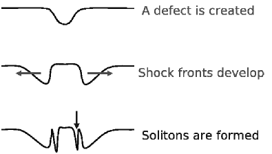
Density engineering as performed in the Harvard experiments Dutton2001a ; ginsberg05 and described in Sec. 2.2 primarily creates localized density voids of the shape of a narrow disk in a slowly-varying background that is determined by the external trapping potential. Simulations of the ensuing dynamics are shown in Fig. 2. The condensate reacts to the creation of the defect and to the missing mean-field repulsion from the removed atoms by rushing in to fill the void. This way, a wave of density depletion emanates from the void at roughly the local speed of sound. However, due to the variation of the speed of sound over the density profile, the wave form steepens at the back to form a shock front. The variation of the speed of sound over the density profile is a general nonlinear sound wave effect, that will become important whenever the density variation is comparable to the density itself. Due to quantum pressure in the superfluid hydrodynamics of the BEC, shock fronts of a size scale smaller than the condensate healing length are not permitted. Instead, dark solitons in the form of planar and modulated wave fronts are shed, as seen in the simulations of Fig. 2 and the schematic of Fig. 3.
During the propagation of the shock wave, a train of solitons is generated in its wake. The solitons shed first are the deepest and equal in amplitude to the original density wave; then shallower solitons follow. Due to the inverse relationship between the depth of the soliton and its speed, the deep solitons which were created earlier move more slowly than the ones created at later times. The deeper solitons also carry a larger amount of excitation energy, which is taken away from the shock wave. During its propagation the shock wave will therefore lose depth and energy and eventually disperse into fast-moving shallow solitons and sound waves. This superfluid version of a shock wave is also called a quantum shock wave.
For theoretical investigations of shock waves in BECs see Refs. zak03:_shock ; perez-garcia:220403 ; kamchatnov:063605 ; damski04pra . The dynamics of shock-wave formation and soliton shedding as described above could not be observed in situ due to limits in the optical resolution for in-trap imaging. However, the resulting trains of dark soliton fronts are clearly seen in the experimental data shown in Fig. 3.
Detailed theoretical studies and experimental observations of shock wave formation and dynamics have been reported recently by Hoefer et al. hoefer:023623 . The decay dynamics of the shock front was described theoretically in terms of a dispersive shock wave. The shock waves studied in this work form from positive density deformations (bright density waves) after the pulsed application of a strongly repulsive, focussed laser beam to a BEC rather than from a collapsing cavity as in the Harvard experiments. Thus the details of the formation and subsequent dynamics of the shock wave are different from the situation described above.
3.2 Snake Instability and Vortex Ring Generation
The decay of planar dark soliton fronts and the subsequent formation of vortex rings were seen in two quite different experiments done in the labs of JILA and Harvard and both published in 2001. The mechanism of decay is a dynamical instability of planar dark solitons, a three-dimensional BEC equivalent of the snake instability of optical dark solitons mamaev96 ; tikhonenko1996ovs . In the following we discuss the observations from both experiments.
3.2.1 Harvard Experiments
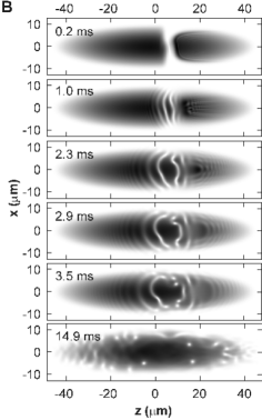
We discussed above how shock waves caused by collapsing voids have lead to the creation of dark soliton wavefronts in the Harvard experiments Dutton2001a ; ginsberg05 . The dynamics of these wave fronts and their decay into vortex rings has been probed experimentally. The size scale of solitons and vortex cores is of the order of the healing length, in this case about 1 m. In order to increase the size of the density features to be more easily imaged, the condensate is suddenly released from the trap and expands due to mean-field pressure while it falls in the gravitational field of the earth. After a typical delay time of about 15 to 20 ms, a single slice of the cloud is selectively imaged by near-resonant absorption after illumination by a pump laser through a slit mask.
The initial expansion image of Fig. 3 clearly shows a train of soliton wave fronts to the right of the dark density feature. During the subsequent time evolution the deepest of the soliton wave fronts undergoes the snake instability while the shallower solitons to the right appear to be more stable. The snaking of the deep soliton front eventually leads to the creation of a vortex ring. The signature of a vortex ring in the experimental images are pairs of white dots. The dots show the depleted core region of the vortex ring intersecting the plane of imaging twice. The slice imaging technique was used to tomographically scan the expanded cloud and explore the three-dimensional structure of the observed defects. The experimental data was found consistent with the assumption that the snake dynamics and vortex generation obey cylindrical symmetry for most of the process, except for late stages of the time evolution as seen in the bottom panels of Fig. 3. This observation suggests that the snake dynamics are seeded by geometrical preconditioning, i.e., bending of soliton fronts due to the geometry of the created defects, trapping potential, etc., rather than being seeded by thermal or quantum fluctuations of the field.
Extensive simulations of the dynamics of the BEC both in the trap and during the expansion phase have revealed that nonlinear wave dynamics still take place during the latter ginsberg05 . Therefore, theoretical modeling is essential for the understanding and interpretation of the experimental results.
3.2.2 JILA Experiments
Using two-component state engineering to create dark solitons in BECs, the JILA group also observed dark solitons decay into vortex rings Anderson2001a . The underlying mechanism of decay is presumed to be again the snake instability, although in the JILA experiment the actual “snaking” was not resolved, as was the case in the Harvard experiment.
As described in Section 2.1, planar dark solitons at JILA were formed in two-component condensates, with atoms of component filling the nodal plane of a planar dark soliton in component . The soliton state and the filling could be separately distinguished with in-trap state-selective phase-contrast imaging, i.e., without releasing the BEC from the trap. This confirmed that the soliton’s density notch bisected the BEC. In an orthogonal coordinate system with axes labeled by and , with along the vertical, the soliton was always created with a normal vector in the plane. Although the soliton orientation was not further controlled, images of filled solitons along the -direction revealed the orientation of each soliton created. Simultaneous images taken along the direction also showed the soliton plane on the occasions when it was horizontal. This non-destructive two-axis imaging technique was used to identify the initial orientation of the soliton nodal planes of the BECs for correlation with subsequent images of soliton decay.
To investigate and study dynamical instabilities of single-component dark solitons, the component- filling was removed with a 100 ms blast of laser light resonant with an electronic transition of the atoms, which left behind a dark soliton in component . The trapped BEC was then held for a variable time, typically less than 100 ms, before release from the confining potential and absorption imaging after 56 ms of expansion. Dark solitons were not observed in expansion images, even though the corresponding in-trap images showed that filled dark solitons were indeed created. Instead, pairs of density dips in the expanded images were observed. For -axis images, two density dips were often seen to lie along a line that approximately matched the orientation of the corresponding filled dark soliton image for that same BEC, taken just before the soliton filling was removed. For example, if an in-trap image along showed that the dark soliton was aligned in a horizontal plane, the two density dips would be seen in the expansion image along an imaginary horizontal line. If a soliton did happen to lie in such a horizontal plane, the soliton nodal plane was then also seen with in-trap images acquired along the direction. The corresponding -direction expansion images in these cases also showed two density dips. Example images are shown in Fig. 4.
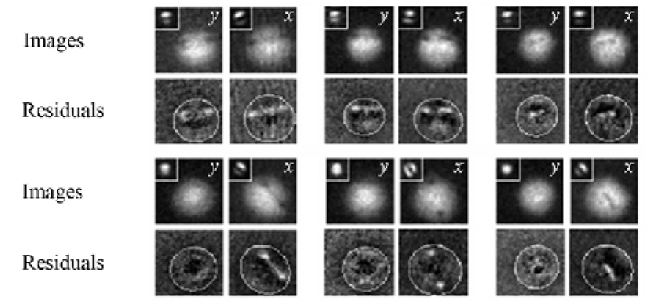
The pairs of density dips in the expansion images indicate the presence of vortex rings in the BECs, the predicted decay products of dynamical instabilities of dark solitons in three-dimensional BECs Feder2000a . Similar to a line vortex (see Chap. VI of this volume), and described earlier in this chapter, a vortex ring in a BEC is characterized by the absence of atoms in a toroidal region within the BEC, with quantized superfluid flow around the fluid-free toroid. An -direction column density profile of a BEC with a vortex ring then appears as a smooth atom cloud with two “holes” separated by the vortex ring diameter, with a faint line connecting the holes. However, if the faint line can not be seen then single-directional imaging does not easily distinguish between single vortex rings and a pair of vortex lines. Therefore, two-directional imaging was used to identify the presence of ring-like structures, as two density-dips were seen in the expansion images from two orthogonal directions for the cases where the in-trap images showed the initial dark soliton nodes to be horizontal.
The experimental results indicated that solitons decayed to vortex rings by the end of the 100 ms removal of the atoms. The observations were consistent with numerical simulations, also described in Ref. Anderson2001a . However, while numerical results predicted the presence of up to three vortex rings, the experimental results revealed no more than a single vortex ring per image. Nevertheless, the experimental results confirmed the theoretical expectations of soliton decay, and demonstrated that multi-dimensional vortex rings were stable topological soliton structures that could be created and observed in BECs.
4 Interacting Dark Solitons and Hybrid Structures
In the Harvard experiment reported in Ref. ginsberg05 , collisions of soliton fronts and vortex rings were probed. In order to facilitate the interaction between nonlinear waves, density engineering was used to generate density voids in two different locations within the same BEC simultaneously. A schematic of the experimental set up is shown in Fig. 1(a) and a simulation of the defect creation stage is shown in Fig. 1(c). The mechanism of soliton shedding from shock waves as described in Sec. 3.1 leads to dark soliton fronts emanating from two centers. In the central part of the BEC this leads to the head-on collision of trains of dark soliton fronts.
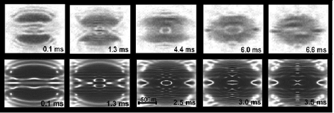
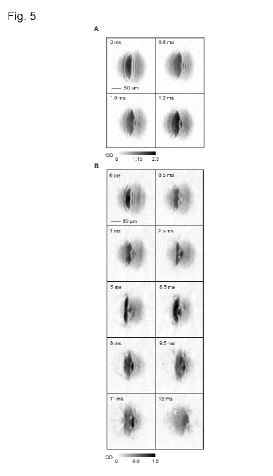
Figure 5 shows the experimental images of the condensate density (top row) and the results of a corresponding Gross-Pitaevskii simulation (bottom row). The images show unexpected intermediate structures in the form of low-density shells around a high-density core of oblate to spherical geometry. These structures are reminiscent of nonlinear Bessel-function-type stationary solutions of the nonlinear Schrödinger equation theocharis:120403 ; theocharis:023609 ; carr:043613 ; ginsberg05 as discussed in Chap. Va. In the experiment, the shell structures are clearly of transient nature and may be closely related to the transient shell structures seen in simulations of head-on collisions of vortex rings komineas:110401 .
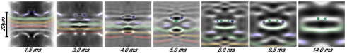
Further insight into the structure of the observed shell structures and their formation can be extracted from the GPE simulations of the experiment as shown in Figs. 5 and 6. These simulations revealed that the shell structures are not present while the BEC is in the trap but rather are formed during the expansion phase. The intricate dynamics that leads to the formation of shell structures involves decay of planar dark soliton fronts via the snake instability into vortex rings, repeated collisions of vortex rings with soliton fronts, the propelling and bending of soliton fronts by the inhomogeneous velocity fields associated with vortex rings, and finally the reconnection processes between soliton wave fronts and annihilation of vortex ring pairs. The simulated time evolution during the expansion phase is shown in Fig. 6.
5 Conclusions
Clearly the experimental investigation of multidimensional solitons has just begun. In particular, as three-dimensional wave-guide structures on atom chips or in the form of toroidal traps become available, it will become possible and indeed, quite important to study the propagation modes of solitary waves in these geometries. Furthermore, as the theoretical work reviewed in Chap. Va suggests, there is much to be expected from the experimental investigation of topological solitons and other nonlinear waves in spinor condensates. We note that the spontaneous formation of topological defects such as spin vortices has been observed very recently in an experiment at Berkeley sadler06:spinBEC by quenching a spinor BEC through a ferromagnetic phase transition.
The authors are indebted to Zac Dutton for a careful reading of the manuscript. JB thanks Lene Hau, Naomi Ginsberg, and Sean Garner for many useful discussions and hospitality during his visits at Harvard University. LDC gratefully acknowledges the support of the National Science Foundation. BPA acknowledges support from the National Science Foundation and the Army Research Office.
References
- (1) S. Burger, K. Bongs, S. Dettmer, W. Ertmer, K. Sengstock, A. Sanpera, G. V. Shlyapnikov, and M. Lewenstein. Phys. Rev. Lett. 83, 5198 (1999).
- (2) J. Denschlag, J. E. Simsarian, D. L. Feder, Charles W. Clark, L. A. Collins, J. Cubizolles, L. Deng, E. W. Hagley, K. Helmerson, W. P. Reinhardt, S. L. Rolston, B. I. Schneider, and W. D. Phillips. Science 287, 97 (2000).
- (3) B. P. Anderson, P. C. Haljan, C. A. Regal, D. L. Feder, L. A. Collins, C. W. Clark, and E. A. Cornell. Phys. Rev. Lett. 86, 2926 (2001).
- (4) Z. Dutton, M. Budde, C. Slowe, and L. V. Hau. Science 293, 663 (2001).
- (5) N. S. Ginsberg, J. Brand, and L. V. Hau. Phys. Rev. Lett. 94, 040403 (2005).
- (6) M. R. Matthews, B. P. Anderson, P. C. Haljan, D. S. Hall, C. E. Wieman, and E. A. Cornell. Phys. Rev. Lett. 83, 2498 (1999).
- (7) B. P. Anderson, P. C. Haljan, C. E. Wieman, and E. A. Cornell. Phys. Rev. Lett. 85, 2857 (2000).
- (8) J. E. Williams and M. J. Holland. Nature 401, 568 (1999).
- (9) L. D. Carr, J. Brand, S. Burger, and A. Sanpera. Phys. Rev. A 63, 051601(R) (2001).
- (10) See Chapter III of this volume for theoretical and experimental reviews of dark solitons in BECs.
- (11) M. R. Matthews, B. P. Anderson, P. C. Haljan, D. S. Hall, M. J. Holland, J. E. Williams, C. E. Wieman, and E. A. Cornell. Phys. Rev. Lett. 83, 3358 (1999).
- (12) K.-J. Boller, A. Imamolu, and S. E. Harris. Phys. Rev. Lett. 66, 2593–2596 (1991).
- (13) J. E. Field, K. H. Hahn, and S. E. Harris. Phys. Rev. Lett. 67, 3062–3065 (1991).
- (14) L. V. Hau, S. E. Harris, Z. Dutton, and C. H. Behroozi. Nature 397, 594 (1999).
- (15) C. Liu, Z. Dutton, C. H. Behroozi, and L. V. Hau. Nature 409, 490 (2001).
- (16) Z. Dutton, N. S. Ginsberg, C. Slowe, and L. V. Hau. Europhysics News 35 (2004).
- (17) M. Zak and I. Kulikov. Phys. Lett. A 307, 99–106 (2003).
- (18) V. M. Perez-Garcia, V. V. Konotop, and V. A. Brazhnyi. Phys. Rev. Lett. 92, 220403 (2004).
- (19) A. M. Kamchatnov, A. Gammal, and R. A. Kraenkel. Phys. Rev. A 69, 063605 (2004).
- (20) B. Damski. Phys. Rev. A 69, 043610 (2004).
- (21) M. A. Hoefer, M. J. Ablowitz, I. Coddington, E. A. Cornell, P. Engels, and V. Schweikhard. Phys. Rev. A 74, 023623 (2006).
- (22) A. V. Mamaev, M. Saffman, and A. A. Zozulya. Phys. Rev. Lett. 76, 2262 (1996). and A. V. Mamaev et al., Phys. Rev. A 54, 870 (1996).
- (23) V. Tikhonenko, J. Christou, B. Luther-Davies, and Y.S. Kivshar. Opt. Lett 21, 1129–1131 (1996).
- (24) D. L. Feder, M. S. Pindzola, L. A. Collins, B. I. Schneider, and C. W. Clark. Phys. Rev. A 62, 053606 (2000).
- (25) G. Theocharis, D. J. Frantzeskakis, P. G. Kevrekidis, B. A. Malomed, and Yuri S. Kivshar. Phys. Rev. Lett. 90, 120403 (2003).
- (26) G. Theocharis, P. Schmelcher, M. K. Oberthaler, P. G. Kevrekidis, and D. J. Frantzeskakis. Phys. Rev. A 72, 023609 (2005).
- (27) L. D. Carr and Charles W. Clark. Phys. Rev. A 74, 043613 (2006).
- (28) S. Komineas and J. Brand. Phys. Rev. Lett. 95, 110401 (2005).
- (29) L. E. Sadler, J. M. Higbie, S. R. Leslie, M. Vengalattore, and D. M. Stamper-Kurn. Nature 443, 312–315 (2006).