Potassium intercalation in graphite: A van der Waals density-functional study
Abstract
Potassium intercalation in graphite is investigated by first-principles theory. The bonding in the potassium-graphite compound is reasonably well accounted for by traditional semilocal density functional theory (DFT) calculations. However, to investigate the intercalate formation energy from pure potassium atoms and graphite requires use of a description of the graphite interlayer binding and thus a consistent account of the nonlocal dispersive interactions. This is included seamlessly with ordinary DFT by a van der Waals density functional (vdW-DF) approach [Phys. Rev. Lett. 92, 246401 (2004)]. The use of the vdW-DF is found to stabilize the graphite crystal, with crystal parameters in fair agreement with experiments. For graphite and potassium-intercalated graphite structural parameters such as binding separation, layer binding energy, formation energy, and bulk modulus are reported. Also the adsorption and sub-surface potassium absorption energies are reported. The vdW-DF description, compared with the traditional semilocal approach, is found to weakly soften the elastic response.
I Introduction
Graphite with its layered structure is easily intercalated by alkali metals (AM) already at room temperature. The intercalated compound has two-dimensional layers of AM between graphite layers,aronson ; nixon1968 ; clarke2 ; k_intercalation ; Di giving rise to interesting properties, such as superconductivity.supercond ; jishi The formation of an AM-graphite intercalate proceeds with adsorption of AM atoms on graphite and absorption of AM atoms below the top graphite layer, after which further exposure to AM atoms leads the AM intercalate compound.
Recent experimentsexp1_interc ; exp2_interc on the structure and electronic properties of AM/graphite systems use samples of graphite that are prepared by heating SiC crystals to temperatures around C.forb This heat-induced graphitization is of great value for spectroscopic studies of graphitic systems, since the resulting graphite overlayers are of excellent quality. sic_grafit The nature of the bonding between the SiC surfaces and graphite has been explored experimentally with photoemission spectroscopy forb2 and theoretically per_eleni_sic with a van der Waals density functional (vdW-DF) theory approach that accounts for the van der Waals (vdW) forces. henrik ; ijqc ; vdwgg ; vxc
Here we investigate with density functional theory (DFT) the effects on the graphite structure and the energetics and the elastic response when potassium is intercalated. The final intercalate compound is C8K. The AM intercalate system is interesting in itself and has been the focus of numerous experimental investigations.wada ; zabelPRB82 ; barnard ; palmer ; li Graphitic systems are also ideal test materials in ongoing theory development that aims at improving the description of the nonlocal interlayer bonds in sparse systems. henrik ; svetla ; girifalco Standard DFT approaches are based on local (local density approximation, LDA) and semilocal approximations (generalized gradient approximation, GGA) dft1 ; dft2 ; dft3 ; dft4 for the electron exchange and correlation. Such regular DFT tools do not treat correctly the weak vdW binding, e.g., the cohesion between (adjacent) graphite layers. The failure of traditional DFT for graphite makes it impossible to obtain a meaningful comparison of the energetics in on-surface AM adsorption and subsurface AM absorption. Conversely, investigations of graphitic systems like C8K permit us to test the accuracy of our vdW-DF development work.
We explore the nature of the bonding of graphite, the process leading to intercalation via adsorption and absorption of potassium, and the nature of potassium-intercalated graphite C8K using a recently developed vdW-DF density functional.vdwgg This choice of functional is essential for a comparison of graphite and C8K properties because of the inability of traditional GGA-based DFT to describe graphite. We calculate the structure and elastic response (bulk modulus ) of pristine graphite and potassium intercalated graphite and we present results for the formation energies of the C8K system.
The intercalation of potassium in graphite is preceded by the adsorption of potassium on top of a graphite surface and potassium absorption underneath the top graphite layer of the surface. In this work we study how potassium bonds to graphite in these two parts of the process towards intercalation. Our vdW-DF investigations of the binding of potassium in or on graphite supplements corresponding vdW-DF studies of the binding of polycyclic aromatic hydrocarbon dimers, of the polyethylene crystal, of benzene dimers, and of polycyclic aromatic hydrocarbon and phenol molecules on graphite.pahsvetla ; PE ; bonog ; phenol ; langreth1 ; langreth2
The outline of the paper is as follows. Section II contains a short description of the materials of interest here: graphite, C8K, and graphite with an adsorbed or absorbed K atom layer. The vdW-DF scheme is described in Sec. III. Section IV presents our results, Sec. V the discussion, and conclusions are drawn in Sec. VI.
II Material structure
Graphite is a semimetallic solid with strong intra-plane bonds and weakly coupled layers. The presence of these two types of bonding results in a material with different properties along the various crystallographic directions.chung For example, the thermal and electrical conductivity along the carbon sheets is two orders of magnitude higher than that perpendicular to the sheets. This specific property allows heat to move directionally, which makes it possible to control the heat transfer. The relatively weak vdW forces between the sheets contribute to another industrially important property: graphite is an ideal lubricant. In addition, the anisotropic properties of graphite make the material suitable as a substrate in electronic studies of ultrathin metal films. mackan_prb64 ; hu ; jinhe ; osterlund
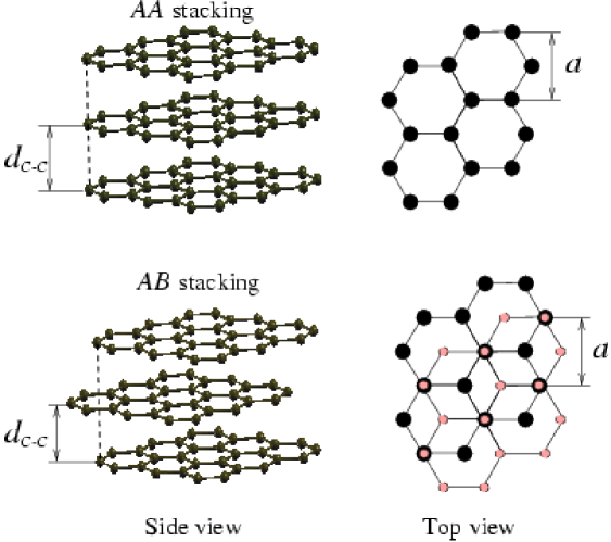
The natural structure of graphite is an stacking, with the graphite layers shifted relative to each other, as illustrated in Fig. 1. The figure also shows hexagonal graphite, consisting of -stacked graphite layers. The in-plane lattice constant and the layer separation is also illustrated. In natural graphite the primitive unit cell is hexagonal, includes four carbon atoms in two layers, and has unit cell side lengths and height .
The physical properties of graphite have been studied in a variety of experimentalbaskin ; eberhardt ; law and theoreticalahuja1 ; holzwarth work. Some of the DFT work has been performed in LDA, which does not provide a physically meaningful account of binding in layered systems.hardnumbers ; ijqc At the same time, using GGA is not an option because it does not bind the graphite layers. For a good description of the graphite structure and nature the vdW interactions must be included.hardnumbers
Alkali metals (AM), except Na, easily penetrate the gallery of the graphite forming alkali metal graphite intercalation compounds. These intercalation compounds are formed through electron exchange between the intercalated layer and the host carbon layers, resulting in a different nature of the interlayer bonding type than that of pristine graphite. The intercalate also affects the conductive properties of graphite, which becomes superconductive in the direction parallel to the planes at critical temperatures below 1 K.supercond ; jishi
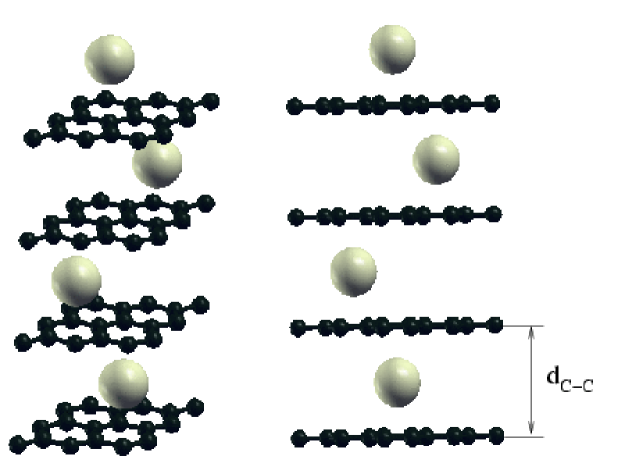
The structure of AM graphite intercalation compounds is characterized by its stage , where is the number of graphite sheets located between the AM layers. In this work we consider only stage-1 intercalated graphite C8K, in which the layers of graphite and potassium alternate throughout the crystal. The primitive unit cell of C8K is orthorhombic and contains sixteen C atoms and two K atoms. In the C8K crystal the K atoms are ordered in a registry with K-K separation 2, where is the in-plane lattice constant of graphite. This separation of the potassium atoms is about 8% larger than that in the natural K bcc crystal (based on experimental values). The carbon sheet stacking in C8K is of type, with the K atoms occupying the sites over the hollows of every fourth carbon hexagon, each position denoted by , , , or , and the stacking of the K atoms perpendicular to the planes being described by the -sequence as illustrated in Fig. 2.
III Computational methods
The first-principle total-energy and electronic structure calculations are performed within the framework of DFT. The semilocal Perdew-Burke-Ernzerhof (PBE) flavordft2 of GGA is chosen for the exchange-correlation functional for the traditional self-consistent calculations underlying the vdW-DF calculations. For all GGA calculations we use the open source DFT code Dacapo,dacapo which employs Vanderbilt ultrasoft pseudopotentials,vanderbilt periodic boundary conditions, and a plane-wave basis set. An energy cut-off of 500 eV is used for the expansion of the wave functions and the Brillouin zone (BZ) of the unit cells is sampled according to the Monkhorst-Pack scheme.monkhorst The self-consistently determined GGA valence electron density as well as components of the energy from these calculations are passed on to the subsequent vdW-DF calculation of the total energy.
For the adsorption and absorption studies a graphite surface slab consisting of 4 layers is used, with a surface unit cell of side lengths twice those in the graphite bulk unit cell (i.e., side lengths ). The surface calculations are performed with a 441 -point sampling of the BZ.
The (pure) graphite bulk GGA calculations are performed with a 884 -point sampling of the BZ, whereas for the C8K bulk structure, in a unit cell at least double the size in any direction, 442 -points are used, consistent also with the choice of -point sampling of the surface slabs.
We choose to describe C8K by using a hexagonal unit cell with four formula units, lateral side lengths approximately twice those of graphite and with four graphite and four K-layers in the direction perpendicular to the layers. C8K can also be described by the previously mentioned primitive orthorhombic unit cell containing two formula units of atoms but we retain the orthorhombic cell for ease of description and for simple implementation of numerically robust vdW-DF calculations.
In all our studies, except test cases, the Fast Fourier Transform (FFT) grids are chosen such that the separation of neighboring points is maximum 0.13 Å in any direction in any calculation.
III.1 vdW density function calculations
In graphite, the carbon layers bind by vdW interactions only. In the intercalated compound a major part of the attraction is ionic, but also here the vdW interactions cannot be ignored. In order to include the vdW interactions systematically in all of our calculations we use the vdW-DF of Ref. vdwgg, . There, the correlation energy functional is divided into a local and a nonlocal part,
| (1) |
where the local part is approximated in the LDA and the nonlocal part is consistently constructed to vanish for a homogeneous system. The nonlocal correlation is calculated from the GGA-based and its gradients by using information about the many-body response of the weakly inhomogeneous electron gas:
| (2) |
The nonlocal kernel can be tabulated in terms of the separation between the two fragments at positions and through the parameters and . Here is a local parameter that depends on the electron density and its gradient at position . The analytic expression for the kernel in terms of and can be found in Ref. vdwgg, .
For periodic systems, such as bulk graphite, C8K, and the graphite surface (with adsorbed or absorbed K-atoms), the nonlocal correlation per unit cell is simply evaluated from the interaction of the points in the unit cell with points everywhere in space () in the three (for bulk graphite and C8K) or two (for the graphite surface) dimensions of periodicity. Thus, the -integral in Eq. (2) in principle requires a representation of the electron density infinitely repeated in space. In practice, the nonlocal correlation rapidly convergesbonog and it suffices with repetitions of the unit cell a few times in each spatial direction. For graphite bulk the -integral is converged when we use a that extends 9 (7) times the original unit cell in directions parallel (perpendicular) to the sheets. For the potassium investigation a significantly larger original unit cell is adopted (see Fig. 2); here a fully converged corresponds to a cell extending five (three) times the original cell in the direction parallel (perpendicular) to the sheets for C8K bulk. To describe the nonlocal correlations (2) for the graphite surface a sufficient extends five times the original unit cell along the carbon sheets.
For the exchange energy we follow the choice of Ref. vdwgg, of using revPBEdft3 exchange. Among the functionals that we have easy access to, the revPBE has proved to be the best candidate for minimizing the tendency of artificial exchange binding in graphite.ijqc
Using the scheme described above to evaluate , the total energy finally reads:
| (3) |
where is the GGA total energy with the revPBE choice for the exchange description and () the GGA (LDA) correlation energy. As our GGA calculations in this specific application of vdW-DF are carried out in PBE, not revPBE, we further need to explicitly replace the PBE exchange in by that of revPBE for the same electron charge density distribution.
III.2 Convergence of the local and nonlocal energy variation
DFT calculations provide physically meaningful results for energy differences between total energies (3). To understand materials and processes we must compare total energy differences between a system with all constituents at relatively close distance and a system of two or more fragments at “infinite” separation (the reference system). Since the total energy (3) consists both of a long-range term and shorter-ranged GGA and LDA terms it is natural to choose different ways to represent the separated fragments for these different long- or short-range energy terms.
For the shorter-range energy parts (LDA and GGA terms) the reference system is a full system with vacuum between the fragments. For LDA and GGA calculations it normally suffices to make sure that the charge density tails of the fragments do not overlap, but here we find that the surface dipoles cause a slower convergence with layer separation. We use a system with the layer separation between the potassium layer and the nearest graphite layer(s) Å (8 Å) as reference for the adsorption (absorption) study.
The evaluation of the nonlocal correlations requires additional care. This is due to technical reasons pertaining to numerically stability in basing the evaluation on the FFT grid used to converge the underlying traditional-DFT calculations. The evaluation of the nonlocal correlation energy, Eq. (2), involves a weighted double integral of a kernel with a significant short-range variation vdwgg . The shape of the kernel makes the evaluation sensitive to the particulars of FFT-type griding,JKPH for example, to the relative position of FFT grid points relative to the nuclei position (for a finite grid-point spacing).
However, robust evaluation of binding- or cohesive-energy contributions by nonlocal correlations can generally be secured by a further splitting of energy differences into steps that minimize the above-mentioned grid sensitivity. The problem of FFT sensitivity of the evaluation is accentuated because the binding in the channel arises as a smaller energy difference between sizable contributions of the system and of the fragments. Conversely, convergence in vdW-DF calculations of binding and cohesive energies can be obtained even at a moderate FFT grid accuracy (0.13 Å used here) by devising a calculational scheme that always maintains identical position of the nuclei relative to grid points in the combined systems as well as in the fragment reference system.
Thus we obtain a numerically robust evaluation of the energy differences by choosing steps for which we can explicitly control the FFT griding. For adsorption and absorption cases we calculate the reference systems as a sum of -contributions for each fragment and we make sure to always position the fragment at the exact same position in the system as in the interacting system. For bulk systems we choose steps in which we exclusively adjust the inter-plane or in-plane lattice constant. Here the reference system is then simply defined as a system with either double (or in some cases quadruple) lattice constant and with a corresponding doubling of the FFT griding along the relevant unit-cell vector.
The cost of full convergence is that, in practice, we often do three or more GGA calculations and subsequent calculations for each point on the absorption, absorption, or formation-energy curve. In addition to the calculations for the full system we have to do one for each of the isolated fragments at identical position in the adsorption/absorption cases and one or more for fragments in the doubled unit-cell and doubled griding reference. We have explicitly tested that using a FFT grid spacing of Å (but not larger) for such reference calculations is sufficient to ensure full convergence in the reported (and total) energy variation for graphitic systems.
III.3 Material formation and sorption energies
The cohesive energy of graphite (G) is the energy gain, per carbon atom, of creating graphite at in-plane lattice constant and layer separation from isolated (spin-polarized) carbon atoms.
| (4) |
where and are total energies per carbon atom. The graphite structure is stable at the minimum of the cohesive energy, at lattice constants and .
The adsorption (absorption) energy for a K-layer over (under) the top layer of a graphite surface is the difference in total energy [from Eq. (3)] for the system at hand minus the total energy of the initial system, i.e., a clean graphite surface and isolated gas-phase potassium atoms. However, due to the above mentioned technical issues in using the vdW-DF we calculate the adsorption and absorption energy as a sum of (artificial) stages leading to the desired system: First the initially isolated, spin-polarized potassium atoms are gathered into a free floating potassium layer with the structure corresponding to a full cover of potassium atoms. By this the total system gains the energy , with
| (5) |
In adsorption the potassium layer is then simply placed on top of the four-layer graphite surface (with the K atoms above graphite hollows) at distance . The system thereby gains a further energy contribution . This leads to an adsorption energy per K-atom
| (6) |
In absorption the top graphite layer is peeled off the graphite surface and moved to a distance far from the remains of the graphite surface. This process costs the system an (“exfoliation”) energy . At the far distance the isolated graphite layer is moved into stacking with the surface, at no extra energy cost. Then, the potassium layer is placed midway between the far-away graphite layer and the remains of the graphite surface. Finally the two layers are gradually moved towards the surface. At distance between the two topmost graphite layers (sandwiching the K-layer) the system has further gained an energy . The absorption energy per K-atom is thus
| (7) |
Similarly, the C8K intercalate compound is formed from graphite by first moving the graphite layers far apart accordion-like (and there shift the graphite stacking from to at no energy cost), then changing the in-plane lattice constant of the isolated graphene layers from to , then intercalating K-layers (in stacking ) between the graphite layers, and finally moving all the K- and graphite layers back like an accordion, with in-plane lattice constant (which has the value at equilibrium).
In practice, a unit cell of four periodically repeated graphite layers is used in order to accommodate the potassium -stacking. The energy gain of creating a graphene sheet from 8 isolated carbon atoms is defined similarly to that of the K-layer:
| (8) |
The formation energy for the C8K intercalate compound per K atom or formula unit, , is thus found from the energy cost of moving four graphite layers apart by expanding the unit cell to large height, , the cost of changing the in-plane lattice constant from to in each of the four isolated graphene layers, , the gain of creating four K-layers from isolated K-atoms, , plus the gain of bringing four K-layers and four graphite layers together in the C8K structure, , yielding
| (9) | |||||
The relevant energies to use for comparing the three different mechanisms of including potassium (adsorption, absorption and intercalation) are thus , and at their respective minimum values.
IV Results
Experimental observations indicate that the intercalation of potassium into graphite starts with the absorption of evaporated potassium into an initially clean graphite surface.footnote This subsurface absorption is preceded by initial, sparse potassium adsorption onto the surface, and proceeds with further absorption into deeper graphite voids. The general view is that the K atoms enter graphite at the graphite step edges.barnard The amount and position of intercalated K atoms is controlled by the temperature and time of evaporation.
Below, we first describe the initial clean graphite system, and the energy gain in (artificially) creating free-floating K-layers from isolated K-atoms. Then we present and discuss our results on potassium adsorption and subsurface absorption, followed by a characterization of bulk C8K.
For the adsorption (absorption) system we calculate the adsorption (absorption) energy curve, including the equilibrium structure. As a demonstration of the need for a relatively fine FFT griding in the vdW-DF calculations we also calculate and compare the absorption curve for a more sparse FFT grid. For the bulk systems (graphite and C8K) we determine the lattice parameters and the bulk modulus. We also calculate the formation energy of C8K and the energy needed to peel off one graphite layer from the graphite surface and compare with experiment.zacharia
IV.1 Graphite bulk structure
The present calculations on pure graphite are for the natural, -stacked graphite (lower panel of Fig. 1). The cohesive energy is calculated at a total of 232 structure values and the equilibrium structure and bulk modulus are then evaluated using the method described in Ref. bulkmodulus, .
Figure 3 shows a contour plot of the graphite cohesive energy variation as a function of the layer separation and the in-plane lattice constant , calculated within the vdW-DF scheme. The contour spacing is 5 meV per carbon atom, shown relative to the energy minimum located at , , (2.476 Å, 3.59 Å). These values are summarized in Table 1 together with the results obtained from a semilocal PBE calculation. As expected, and discussed in Ref. henrik, , the semilocal PBE calculation yields unrealistic results for the layer separation. The table also presents the corresponding experimental values. Our calculated lattice values obtained using vdW-DFT are in good agreement with experiment,baskin and close to those found from the older vdW-DF of Refs. henrik, and ijqc, , (in which we for assume translational invariance of along the graphite planes,) at (2.47 Å, 3.76 Å).
Consistent with experimental reportswada and our previous calculationshardnumbers ; ijqc ; henrik we find graphite to be rather soft, indicated by the bulk modulus value. Since in-plane compression is very hard in graphite most of the softness suggested by (the isotropic) comes from compression perpendicular to the graphite layers, and the value of is expected to be almost identical to the elastic coefficient.wada ; henrik

| Graphite | C8K | ||||||
| PBE | vdW-DF | Exp. | PBE | vdW-DF | Exp. | ||
| (Å) | 2.473 | 2.476 | 2.459a | 2.494 | 2.494 | 2.480b | |
| (Å) | 3.59 | 3.336a | 5.39 | 5.53 | 5.35c | ||
| (GPa) | 27 | 37 | 26 | 47de | |||
| aRef. baskin, . bRef. nixon1969, . cRef. k_intercalation, . dRef. wada, . | |||||||
| eValue presented is for ; for laterally rigid materials, like | |||||||
| graphite and C8K, is a good approximation of . | |||||||
We find the energy cost of peeling off a graphite layer from the graphite surface (the exfoliation energy) to be meV per () unit cell, i.e., meV per surface carbon atom (Table 2). A recent experimentzacharia measured the desorption energy of polycyclic aromatic hydrocarbons (basically flakes of graphite sheets) off a graphite surface. From this experiment the energy cost of peeling off a graphite layer from the graphite surface was deduced to meV/atom.
Our value meV/C-atom is also consistent with a separate vdW-DF determinationpahsvetla of the binding ( meV per in-plane atom) between two (otherwise) isolated graphene sheets.
For the energies of the absorbate system and of the C8K intercalate a few other graphite-related energy contributions are needed. The energy of collecting C atoms to form a graphene sheet at lattice constant from isolated (spinpolarized) atoms is given by ; we find that changing the lattice constant from to the equilibrium value of C8K causes this energy to change a mere 30 meV per () sheet. The contribution is the energy of moving bulk graphite layers (in this case four periodically repeated layers) far away from each other, by expanding the unit cell along the direction perpendicular to the layers. Thus, taking the number of atoms and layers per unit cell into account. We find the value meV per () four-layer unit cell. This corresponds to meV per C atom, again consistent with our result for the exfoliation energy, meV.
IV.2 Creating a layer of K-atoms
The (artificial) step of creating a layer of potassium atoms from isolated atoms releases a significant energy . This energy contains the energy variation with in-plane lattice constant and the energy cost of changing from a spin-polarized to a spin-balanced electron configuration for the isolated atom.wilkins
The creation of the K-layer provides an energy gain which is about half an eV per potassium atom, depending on the final lattice constant. With the graphite lattice constant the energy change, including the spin-change cost, is meV per K atom in vdW-DF ( meV when calculated within PBE), whereas meV in vdW-DF.
IV.3 Graphite-on-surface adsorption of potassium
The potassium atoms are adsorbed on a usual -stacked graphite surface. We consider here full (one monolayer) coverage, which is one potassium atom per () graphite surface unit cell. This orders the potassium atoms in a honeycomb structure with lattice constant 2, and a nearest-neighbor distance within the K-layer of .
The unit cell used in the standard DFT calculations for adsorption and absorption has a height of 40 Å and includes a vacuum region sufficiently big that no interactions (within GGA) can occur between the top graphene sheet and the slab bottom in the periodically repeated image of the slab. The vacuum region is also large in order to guarantee that the separation from any atom to the dipole layerbengtsson always remains larger than 4 Å.
In the top panel of Fig. 4 we show the adsorption energy per potassium atom. The adsorption energy at equilibrium is meV per K atom at distance Å from the graphite surface.
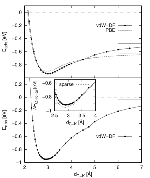
For comparison we also show the adsorption curve calculated in a PBE-only traditional DFT calculation. Since the interaction between the K-layer and the graphite surface has a short-range component to it, even GGA calculations, such as the PBE curve, show significant binding ( meV/K-atom at Å). This is in contrast to the pure vdW binding between the layers in clean graphite.ijqc ; henrik Note that the asymptote of the PBE curve is different from that of the vdW-DF curve, this is due to the different energy gains () in collecting a potassium layer from isolated atoms when calculated in PBE or in vdW-DF.
For K-adsorption the vdW-DF and PBE curves agree reasonably well, and the use of vdW-DF for this specific calculation is not urgently necessary. However, in order to compare the adsorption results consistently to absorption, intercalation and clean graphite, it is necessary to include the long-range interactions through vdW-DF. As shown for the graphite bulk results above, PBE yields quantitatively and qualitatively wrong results for the layer separation.
IV.4 Graphite-subsurface absorption of potassium
The first subsurface adsorption of K takes place in the void under the top-most graphite layer. The surface absorption of the first K-layer causes a lateral shift of the top graphite sheet, resulting in a K stacking of the graphite. We have studied the bonding nature of this absorption process by considering a full -intercalated potassium layer in the subsurface of a four layer thick graphite slab.
Following the receipt of Section III for the absorption energy (7) the energies are approximated by those from a four-layer intercalated graphite slab with the stacking K, and the values are shown in the inset of Fig. 4. The absorption energy is given by the curve in the bottom panel of Fig. 4, and its minimum is meV per K atom at Å.
To investigate what grid spacing is sufficiently dense to obtain converged total-energy values in vdW-DF we do additional calculations in the binding distance region with a more sparse grid. Specifically, the inset of Fig. 4 compares the vdW-DF calculated at full griding with one that uses only every other FFT grid point in each direction, implying a grid spacing for (but not for the local terms) which is maximum 0.26 Å. We note that using the full grid yields smaller absolute values of the absorption energy. We also notice that the effect is more pronounced for small separations than for larger distances. Thus given resources, the dense FFT grid calculations are preferred, but even the less dense FFT grid calculations yield reasonably well-converged results. In all calculations (except tests of our graphitic systems) we use a spacing with maximum 0.13 Å between grid points. This is a grid spacing for which we have explicitly tested convergence of the vdW-DF for graphitic systems given the computational strategy described and discussed in Sec. III.
IV.5 Potassium-intercalated graphite
| [meV/atom] | [meV/atom] | [meV/] | [meV/] | |
| vdW-DF | ||||
| PBE | ||||
| Exp. | a | |||
| aRef. zacharia, . bRef. aronson, . | ||||
When potassium atoms penetrate the gallery of the graphite, they form planes that are ordered in a fashion along the planes. The K intercalation causes a shift of every second carbon layer resulting into an stacking of the graphite sheets. The K atoms then simply occupy the sites over the hollows of every fourth carbon hexagon. The order of the K atoms perpendicular to the planes is described by the stacking, illustrated in Fig. 2.
For the potassium intercalated compound C8K we calculate in standard DFT using PBE the total energy at 132 different combinations of the structural parameters and . The charge densities and energy terms of these calculations are then used as input to vdW-DF. The equilibrium structure and elastic properties () both for the vdW-DF results and for the PBE results are then evaluated with the same method as in the graphite case. bulkmodulus

Figure 5 shows a contour plot of the C8K formation energy, calculated in vdW-DF, as a function of the C-C layer separation () and the in-plane periodicity () of the graphite-layer structure. The contour spacing is 20 meV per formula unit and are shown relative to the energy minimum at (, 2.494 Å, 5.53 Å).
V Discussion
Table 1 presents an overview of our structural results obtained with the vdW-DF for graphite and C8K. The table also contrasts the results with the corresponding values calculated with PBE where available. The vdW-DF value Å for the C8K layer separation is 3% larger than the experimentally observed value whereas the PBE value corresponds to less than a 1% expansion. Our vdW-DF result for the C8K bulk modulus (26 GPa) is also softer than the PBE result (37 GPa) and further away from the experimental estimates (47 GPa) based on measurements of the elastic response.wada A small overestimation of atomic separation is consistent with the vdW-DF behavior that has been documented in a wide range of both finite and extended systems.henrik ; ijqc ; vdwgg ; vxc ; pahsvetla ; PE ; langreth1 ; langreth2 This overestimation results, at least in part, from our choice of parametrization of the exchange behavior — an aspect that lies beyond the present vdW-DF implementation which focuses on improving the account of the nonlocal correlations, per se. It is likely that systematic investigations of the exchange effects can further refine the accuracy of vdW-DF implementations.footnote3 In any case, vdW-DF theory calculations represent, in contrast to PBE, the only approach to obtain a full ab initio characterization of the AM intercalation process.
The C8K system is more compact than graphite and this explains why PBE alone can here provide a good description of the materials structure and at least some materials properties, whereas it fails completely for graphite. The distance between the graphene sheets upon intercalation of potassium atoms is stretched compared to that of pure graphite, but the (K-)layer to (graphite-)layer separation, Å, is significantly less than the layer-layer separation in pure graphite. This indicates that C8K is likely held together, at least in part, by shorter-ranged interactions.
Table 2 documents that the vdW binding nevertheless plays an important role in the binding and formation of C8K. The table summarizes and contrasts our vdW-DF and PBE results for graphite exfoliation and layer binding energies as well as C8K interlayer binding and formation energies. The vdW-DF result for the C8K formation energy is smaller than experimental measurements by 31% but it nevertheless represent a physically motivated ab initio calculation. In contrast, the C8K formation energy is simply unavailable in PBE because PBE, as indicated, fails to describe the layer binding in graphite. Moreover, for the vdW-DF/PBE comparisons that we can make — for example, of the C8K layer interaction — the vdW-DF is found to significantly strengthen the bonding compared with PBE.
It is also interesting to note that the combination of shorter-ranged and vdW bonding components in C8K yields a layer binding energy that is close to that of the graphite case. In spite of the difference in nature of interactions, we find almost identical binding energies per layer for the case of the exfoliation and accordion in graphite and for the accordion in C8K. This observation testifies to a perhaps surprising strength of the so-called soft-matter vdW interactions.
In a wider perspective our vdW-DF permits a first comparison of the range of AM-graphite systems from adsorption over absorption to full intercalation and thus insight on the intercalation progress. Assuming a dense configuration, we find that the energy for potassium adsorption and absorption is nearly degenerate with an indication that absorption is slightly preferred, consistent with experimental behavior. We also find that the potassium absorption may eventually proceeds towards full intercalation thanks to a significant release of formation energy.
VI Conclusions
The potassium intercalation process in graphite has been investigated by means of the vdW-DF density functional method. This method includes the dispersive interactions needed for a consistent investigation of the intercalation process. For clean graphite the vdW-DF predicts — contrary to standard semilocal DFT implementations — a stabilized bulk system with equilibrium crystal parameters in close agreement with experiments. Two limits of the absorption process have been investigated by the vdW-DF, namely single layer subsurface absorption and the fully potassium intercalated stage-1 crystal C8K. Here the vdW-DF is shown to enhance the (semi-)local type of bonding described by traditional approaches. The significant impact on the materials behavior indicates that the vdW-DF is needed not only for a consistent description of sparse matter systems that are solely stabilized by dispersion forces, but also for their intercalates.
We thank D.C. Langreth and B.I. Lundqvist for stimulating discussions. Partial support from the Swedish Research Council (VR), the Swedish National Graduate School in Materials Science (NFSM), and the Swedish Foundation for Strategic Research (SSF) through the consortium ATOMICS is gratefully acknowledged, as well as allocation of computer time at UNICC/C3SE (Chalmers) and SNIC (Swedish National Infrastructure for Computing).
References
- (1) S. Aronson, F.J. Salzano, and D. Ballafiore, J. Chem. Phys. 49, 434 (1968).
- (2) D.E. Nixon and G.S. Parry, J. Phys. D 1, 291 (1968).
- (3) R. Clarke, N. Wada, and S.A. Solin, Phys. Rev. Lett. 44, 1616 (1980).
- (4) M.S. Dresselhaus and G. Dresselhaus, Adv. Phys. 30, 139 (1981).
- (5) D.P. DiVincenzo and E.J. Mele, Phys. Rev. B 32, 2538 (1985).
- (6) N.B. Hannay, T.H. Geballe, B.T. Matthias, K. Andreas, P. Schmidt, and D. MacNair, Phys. Rev. Lett. 14, 225 (1965).
- (7) R.A. Jishi and M.S. Dresselhaus, Phys. Rev. B 45, 12465 (1992).
- (8) T. Kihlgren, T. Balasubramanian, L. Walldén, and R. Yakimova, Surf. Sci. 600, 1160 (2006).
- (9) M. Breitholtz, T. Kihlgren, S.-Å. Lindgren, and L. Walldén, Phys. Rev. B 66, 153401 (2002).
- (10) I. Forbeaux, J.-M. Themlin, and J.-M. Debever, Phys. Rev. B 58, 16396 (1998).
- (11) T. Kihlgren, T. Balasubramanian, L. Walldén, and R. Yakimova, Phys. Rev. B 66, 235422 (2002).
- (12) I. Forbeaux, J.-M. Themlin, A. Charrier, F. Thibaudau, and J.-M. Debever, Appl. Surf. Sci. 162–163, 406 (2000).
- (13) E. Ziambaras, Ph.D. thesis, Chalmers (2006).
- (14) H. Rydberg, M. Dion, N. Jacobson, E. Schröder, P. Hyldgaard, S.I. Simak, D.C. Langreth, and B.I. Lundqvist, Phys. Rev. Lett. 91, 126402 (2003).
- (15) D.C. Langreth, M. Dion, H. Rydberg, E. Schröder, P. Hyldgaard, and B.I. Lundqvist, Int. J. Quantum Chem. 101, 599 (2005).
- (16) M. Dion, H. Rydberg, E. Schröder, D.C. Langreth, and B.I. Lundqvist, Phys. Rev. Lett. 92, 246401 (2004); 95, 109902(E) (2005).
- (17) T. Thonhauser, V.R. Cooper, S. Li, A. Puzder, P. Hyldgaard, and D.C. Langreth, Van der Waals density functional: Self-consistent potential and the nature of the van der Waals bond, http://arxiv.org/abs/cond-mat/0703442
- (18) N. Wada, R. Clarke, and S.A. Solin, Solid State Comm. 35, 675 (1980).
- (19) H. Zabel and A. Magerl, Phys. Rev. B 25, 2463 (1982).
- (20) J.C. Barnard, K.M. Hock and R.E. Palmer, Surf. Science 287–288, 178 (1993).
- (21) K. M. Hock and R. E. Palmer, Surf. Science 284, 349 (1993).
- (22) Z.Y. Li, K.M. Hoch, and R.E. Palmer, Phys. Rev. Lett. 67, 1562 (1991).
- (23) S.D. Chakarova and E. Schröder, Materials Science and Engineering C 25, 787 (2005).
- (24) L.A. Girifalco and M. Hodak, Phys. Rev. B 65, 125404 (2002).
- (25) J.P. Perdew, J.A. Chevary, S.H. Vosko, K.A. Jackson, M.R. Pederson, D.J. Singh, and C. Fiolhais, Phys. Rev. B 48, 6671 (1992).
- (26) J.P. Perdew, K. Burke, and M. Ernzerhof, Phys. Rev. Lett. 77, 3865 (1996).
- (27) Y. Zhang and W. Yang, Phys. Rev. Lett. 80, 890 (1998).
- (28) B. Hammer, L.B. Hansen, and J.K. Nørskov, Phys. Rev. B 59, 7413 (1999).
- (29) S.D. Chakarova-Käck, J. Kleis, and E. Schröder, Appl. Phys. Rep. 2005-16 (2005).
- (30) J. Kleis, B.I. Lundqvist, D.C. Langreth, and E. Schröder, Towards a working density-functional theory for polymers: First-principles determination of the polyethylene crystal structure, http://arxiv.org/abs/cond-mat/0611498
- (31) S.D. Chakarova-Käck, E. Schröder, B.I. Lundqvist, and D.C. Langreth, Phys. Rev. Lett. 96, 146107 (2006).
- (32) S.D. Chakarova-Käck, Ø. Borck, E. Schröder, and B.I. Lundqvist, Phys. Rev. B 74, 155402 (2006).
- (33) A. Puzder, M. Dion, and D.C. Langreth, J. Chem. Phys. 124, 164105 (2006).
- (34) T. Thonhauser, A. Puzder, and D.C. Langreth, J. Chem. Phys. 124, 164106 (2006).
- (35) D.D.L. Chung, J. Mat. Sci. 37, 1475 (2002).
- (36) M. Breitholtz, T. Kihlgren, S.-Å. Lindgren, H. Olin, E. Wahlström, and L. Walldén, Phys. Rev. B 64, 073301 (2001).
- (37) Z.P. Hu, N.J. Wu, and A. Ignatiev, Phys. Rev. B 33, 7683 (1986).
- (38) J. Cui, J.D. White, R.D. Diehl, J.F. Annett, and M.W. Cole, Surf. Sci. 279, 149 (1992).
- (39) L. Österlund, D.V. Chakarov, and B. Kasemo, Surf. Sci. 420, L437 (1991).
- (40) Y. Baskin and L. Meyer, Phys. Rev. 100, 544 (1955).
- (41) W. Eberhardt, I.T. McGovern, E.W. Plummer, and J.E. Fisher, Phys. Rev. Lett. 44, 200 (1980).
- (42) A.R. Law, J.J. Barry, and H.P. Hughes, Phys. Rev. B 28, 5332 (1983).
- (43) R. Ahuja, S. Auluck, J. Trygg, J.M. Wills, O. Eriksson, and B. Johansson, Phys. Rev. B 51, 4813 (1995).
- (44) N.A.W. Holzwarth, S.G. Louie, and S. Rabii, Phys. Rev. B 26, 5382 (1982).
- (45) H. Rydberg, N. Jacobson, P. Hyldgaard, S.I. Simak, B.I. Lundqvist, and D.C. Langreth, Surf. Sci. 532-535, 606 (2003).
- (46) Open-source plane-wave DFT computer code Dacapo, http://www.fysik.dtu.dk/CAMPOS/
- (47) D. Vanderbilt, Phys. Rev. B 41, 7892 (1990).
- (48) H.J. Monkhorst and J.D. Pack, Phys. Rev. B 13, 5188 (1976).
- (49) D.C. Langreth, private communication; J. Kleis and P. Hyldgaard, unpublished.
- (50) The transition from on-surface adsorption to subsurface absorption is identified in experiment by a work function change, Refs. barnard, and palmer, .
- (51) R. Zacharia, H. Ulbricht, and T. Hertel, Phys. Rev. B 69, 155406 (2004).
- (52) E. Ziambaras and E. Schröder, Phys. Rev. B 68, 064112 (2003).
- (53) D.E. Nixon and G.S. Parry, J. Phys. C 2, 1732 (1969).
- (54) O. Gunnarsson, B.I. Lundqvist, and J.W. Wilkins, Phys. Rev. B 10, 1319 (1974). Since no spin-polarized version of vdW-DF exists at present, we calculate the the energy cost for changing the spin of isolated potassium atoms in PBE. The spin-change cost is thus determined to be 26 meV/K-atom.
- (55) L. Bengtsson, Phys. Rev. B 59, 12301 (1999), and references therein.
- (56) The choice of exchange flavor in vdW-DF was set in Ref. ijqc, to avoid artificial bonding in noble-gas systems and to better mimic exact exchange calculations for those systems. However, it is far from certain and even unlikely that the conclusions drawn for noble-gas systems carry over to bonding separations smaller than 3 Å.