Interference and X Networks with Noisy Cooperation and Feedback
Abstract
The Gaussian -user interference and X channels are investigated with no instantaneous channel state information (CSI) at transmitters. First, it is assumed that the CSI is fed back to all nodes after a finite delay (delayed CSIT), and furthermore, the transmitters operate in full-duplex mode, i.e., they can transmit and receive simultaneously. Achievable results are obtained on the degrees of freedom (DoF) of these channels under the above assumption. It is observed that, in contrast with no CSIT and full CSIT models, when CSIT is delayed, the achievable DoFs for both channels with full-duplex transmitter cooperation are greater than the best available achievable results on their DoF without transmitter cooperation. Our results are the first to show that the full-duplex transmitter cooperation can potentially improve the channel DoF with delayed CSIT. Then, -user interference and X channels are considered with output feedback, wherein the channel output of each receiver is causally fed back to its corresponding transmitter. Our achievable results with output feedback demonstrate strict DoF improvements over those with the full-duplex delayed CSIT when in the -user interference channel and in the X channel. Next, the combination of delayed CSIT and output feedback, known as Shannon feedback, is studied and strictly higher DoFs compared to the output feedback model are achieved in the -user interference channel when or , and in the X channel when . Although being strictly greater than and increasing with size of the networks, the achievable DoFs in all the models studied in this paper approach limiting values not greater than .
I Introduction
The crucial role of feedback in reliability, throughput, and complexity of transmission over communication networks has made it an indispensable ingredient of all modern communication systems. In spite of the first result by Shannon that shows the capacity of a memoryless point-to-point channel is not increased with feedback [2], it has been proved that feedback enlarges the capacity region of several multi-user channels. The capacity regions of the additive white Gaussian noise (AWGN) multiple-access, broadcast, and interference channels are enlarged with noiseless output feedback as shown in [3, 4, 5]. It was shown in [6] that even a single output feedback link from one of receivers enlarges the capacity region of two-user AWGN broadcast channel. In fading AWGN channels, since it is commonly assumed that each receiver obtains the channel state information (CSI) instantaneously and perfectly, the channel output(s) and/or the CSI can be fed back to the transmitter(s). Without any feedback, and hence, without CSI at any transmitter (no CSIT), the capacity regions of single-input single-output (SISO) fading two-user broadcast and two-user Z-interference channels have been characterized to within constant number of bits (see [7, 8] and references therein). Also, it was shown in [9] that a large class of multiple-input single-output (MISO) multi-user channels including broadcast, interference, X, and cognitive radio channels can achieve no more that one degree of freedom (DoF) with no CSIT. As a first order approximation of the channel capacity, the DoF of a channel characterizes its sum-capacity in high signal-to-noise-ratio (SNR) regime, i.e.,
| (1) |
where is the sum-capacity for a given SNR and is the channel sum-DoF, or simply, DoF.
When there is CSI feedback to transmitter(s) and the channel variations are not too fast, it is commonly assumed that the CSI obtained through feedback links is valid at least over the current channel use, and hence, the transmitter(s) have access to perfect and instantaneous CSI (full CSIT). In this case, using the interference alignment technique, the -user SISO interference channel (IC) and SISO X channel were shown to have and DoF, respectively, in [10, 11]. If the channel coefficients are i.i.d. over time and the feedback delay is greater than a channel use period, the CSI obtained through feedback links is outdated. This makes the “full CSIT assumption” practically implausible, since the CSIT expires prior to the beginning of each channel use. Nevertheless, it has been established that the outdated CSIT (known as delayed CSIT) yields DoF gain in broadcast channels [12, 13, 14] and interference and X channels [15, 16, 17, 18, 19, 20, 21]. The two-user MIMO interference channel with both delayed CSIT and output feedback has been recently studied in [22, 23].
Output feedback in multi-user channels with distributed transmitters, such as IC and X channel, naturally provides some level of transmitter cooperation. As such, there are connections between communication over these channels with feedback and that with transmitter cooperation. A common cooperation setup is to enable transmitters to operate in full-duplex mode, i.e., to transmit and receive simultaneously. The two-user IC with full-duplex transmitters and with full CSIT was investigated in [24, 25, 26, 27, 28]. In [25, 26, 28] achievable schemes are proposed based on further splitting the common and/or private information of the HK scheme into two parts, namely, non-cooperative and cooperative part. The cooperative part is decoded at the other transmitter as well to be able to cooperate in delivering the information to the desired receiver. By developing an upper bound, the sum-capacity of the two-user Gaussian IC with full-duplex transmitters was obtained to within a constant number of bits in [25]. Moreover, it was shown in [29, 30] that under the full CSIT assumption, the full-duplex cooperation and/or output feedback cannot increase DoF of the -user IC and X channel. In other words, the full-duplex cooperation as well as output feedback can only yield “additive” capacity increase in the aforementioned channels when the full CSI is available at transmitters. With no CSIT also the full-duplex transmitter cooperation cannot help these channels to achieve more than one DoF, since the MISO broadcast channel DoF is equal to one with no CSIT[9].
In this paper, we address the problem of communication over the -user SISO IC and SISO X channel with no instantaneous CSIT, and study the impact of full-duplex transmitter cooperation and/or different types of feedback on DoF of these channels. Specifically, after presenting the problem formulation in Section II, we start by giving some illustrative examples for the interference channel in Section III and X channel in Section IV. These examples highlight our interference alignment ideas for the channels with a few number of users. Then, we present our main results in Section V, and provide the proofs in subsequent sections. In particular, we consider these channels with delayed CSIT and full-duplex transmitter cooperation in Section VI. Regarding the full-duplex CSI, we assume that the source nodes (transmitters) have only access to their incoming full-duplex CSI. We propose transmission schemes that achieve DoFs greater than the best previously reported DoFs for these channels with delayed CSIT but without transmitter cooperation [19].
In Section VII, we consider the same channels with output feedback, wherein we assume that each transmitter has a causal access to the output of its paired receiver through a feedback link. This is indeed a limited output feedback (in contrast to providing each transmitter with the outputs of more than one receiver), however, the term “limited” will be henceforth dropped for brevity. Therefore, in the X channel, we hereafter consider only with a one-to-one mapping between transmitters and receivers for feedback assignment. The -user IC and X channel with output feedback were previously investigated in [15], wherein and DoF were respectively achieved. While achieving the same DoFs for the -user IC and X channel, our main contribution here is proposing multi-phase transmission schemes for the general -user cases that achieve DoF values strictly increasing in .
Next, we study the -user SISO IC and SISO X channel with delayed CSIT and output feedback in Section VIII. Under this assumption, which is referred to as Shannon feedback, we propose multi-phase transmission schemes capturing both the delayed CSI and output feedback to cooperatively transmit over the channel. The achieved DoFs are strictly increasing in and greater than those we achieved with output feedback for and in the -user IC and for in the X channel. The achievable results will be compared and discussed in Section IX, and finally, the paper is concluded in Section X.
II Problem Formulation
Let us make the following definitions:
Definition 1 (-user SISO AWGN Interference Channel)
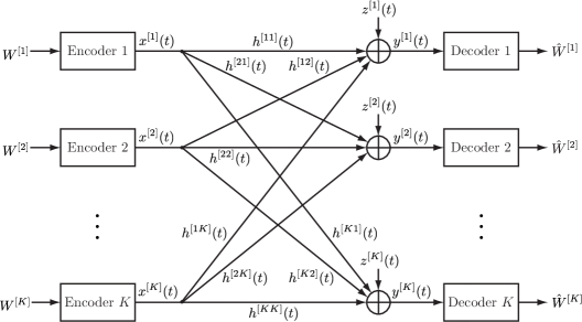
A set of transmitters and receivers, depicted in Fig. 1, where transmitter (TXi), , wishes to communicate a message of rate to receiver (RXi) over a block of channel uses (or time slots). In time slot , , signal is transmitted by TXi, , and signal is received by RXj, , where
| (2) |
and is the channel coefficient from TXi to RXj, and is the additive white Gaussian noise at RXj. The transmitted signal , , is subject to power constraint , i.e., . The channel matrix in time slot is defined as . The channel coefficients are independent and identically distributed (i.i.d.) across all nodes as well as time slots. The channel coefficients are assumed to be drawn according to a finite-variance continuous distribution. Each receiver RXj, , knows all its incoming channel coefficients in time slot , i.e., , perfectly and instantaneously.
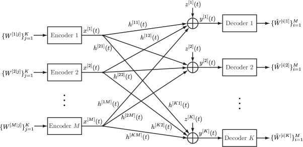
Definition 2 ( SISO AWGN X Channel)
A set of transmitters and receivers as depicted in Fig. 2, where TXi, , has a message of rate for each receiver RXj, . The input-output relationship of this channel is also given by 2 with the summation taken over the transmitters and with the same channel parameters and power constraint at each transmitter. The channel matrix here is a matrix defined as . Similar to the IC, each receiver RXj, , knows all its incoming channel coefficients in time slot , i.e., , perfectly and instantaneously.
Definition 3 (Feedback Models)
We assume that each receiver knows channel coefficients of the other receivers with one time slot delay. Moreover, three different feedback models are considered in this paper, which are defined as follows:
-
•
Delayed CSIT: The channel matrix will become available at all transmitters with one time slot delay via noiseless feedback links.
-
•
Output Feedback: Each channel output , , will become available at TXi with one time slot delay via a noiseless feedback link. Therefore, for the X channel, we only consider under the output feedback assumption.
-
•
Shannon Feedback: The transmitters have access to both delayed CSIT and output feedback as defined above. Therefore, for the X channel, we only consider under the Shannon feedback assumption.
Definition 4 (Full-duplux Transmitter Cooperation)
The transmitters are said to operate in full-duplex mode if they can transmit and receive simultaneously. In full-duplex mode, the received signal of TXi in time slot is given by
| (3) | |||||
| (4) |
The noise terms and channel coefficients are assumed to be i.i.d. across all transmitters and time. No feedback link is available between the transmitters, and hence, TXi is assumed to have only its incoming full-duplex channel coefficients, i.e., in the IC and in the X channel, perfectly and instantaneously.
Definition 5 (Block Code with Feedback)
A code of block length and rate with feedback in the -user IC is defined as sets of encoding functions , , such that
| (5) |
together with decoding functions , , such that , where is the side information available at TXi before time slot , which will be defined later in this section. Similarly, A code of block length and rate with feedback in the X channel is defined as sets of encoding functions , , such that
| (6) |
together with decoding functions , , such that .
Definition 6 (Transmitter Side Information)
Using Definitions 3 and 4, the following feedback and/or transmitter cooperation models will be investigated in this paper, each of which is equivalent to a certain transmitter side information:
-
(a)
The -user IC and X channel with delayed CSIT and full-duplex transmitter cooperation:
(7) (8) -
(b)
The -user IC and X channel with output feedback:
(9) -
(c)
The -user IC and X channel with Shannon feedback:
(10)
Definition 7 (Probability of Error, Achievable Rate, and Capacity Region)
Defining the probability of error of a code as the probability of decoding any of the transmitted messages incorrectly, a rate tuple is said to be achievable if there exists a sequence of codes such that their probability of error goes to zero as . The closure of the set of all achievable rate tuples is called the capacity region of the channel with power constraint and is denoted by .
Definition 8 (DoF)
If is an achievable rate tuple, then is called an achievable DoF tuple and is called an achievable sum-DoF or simply achievable DoF. The closure of the set of all achievable DoF tuples is called the DoF region and denoted by , and the channel sum-DoF, or simply DoF, is defined as .
In the following two sections, we elaborate on our transmission schemes for examples of the IC with a few number of users. Each channel will be investigated under each of the following assumptions defined in Definition 6:
-
(a)
Full-duplex transmitter cooperation and delayed CSIT (which is also called full-duplex delayed CSIT in this paper);
-
(b)
Output feedback;
-
(c)
Shannon feedback.
III Illustrative Examples: Interference Channel
Note that for the two-user IC, none of the assumptions (a)-(c) can help to achieve more than one DoF. This follows from the fact that DoF of this channel with full CSIT is equal to , and full-duplex cooperation and/or output feedback cannot increase the channel DoF with full CSIT[30]. Hence, we start by the -user IC and present our transmission scheme under each of the assumptions (a)-(c). Subsequently, we consider the -user IC to illustrate how our transmission techniques are generalized to the IC with more users. Let us introduce some notations which will be used only in this section and Section IV:
Notation 1
In the IC, we denote fresh information symbols of TX1, TX2, TX3, and TX4 (intended for their paired receivers) by , , , and variables, respectively. Each of these symbols is selected from a Gaussian codeword which is intended to be decoded at its corresponding receiver.
Notation 2
The transmission schemes are multiphase. A linear combination of transmitted symbols which is received by RX1 is denoted by if we are in phase of the scheme, and by or if we are in phase , where is the time index. Similarly, , , and and their primed versions denote the linear combinations available at RX2, RX3, and RX4, respectively. A linear combination which is available at a receiver but is not desired by that receiver is coloured by a colour specified to that receiver. In particular, “blue”, “red”, “green”, and “yellow” are assigned to RX1 to RX4, respectively.
III-A -user Interference Channel
The schemes we propose for the -user IC under the assumptions (a)-(c) are motivated by the scheme proposed in [15] for the -user IC with output feedback, i.e., assumption (b). Indeed, the scheme proposed here for the -user IC with output feedback is a modified version of the scheme proposed in [15] and achieves the same DoF of . The modification is such that our scheme can be systematically generalized to larger networks. For the full-duplex delayed CSIT and Shannon feedback, our transmission schemes also achieve DoF. Each scheme operates in distinct phases. Since phase is the same for all three schemes, we present phase only once, and then present phase under each assumption separately.
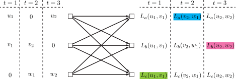
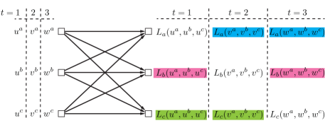
Phase (-user IC):
This phase takes time slots, during which information symbols , , and are fed to the system respectively by TX1, TX2, and TX3 as follows:
First time slot: TX1 and TX2 transmit and , respectively, while TX3 is silent. Hence, ignoring the noise, RX1 and RX2 each receive one linear equation in terms of and by the end of the first time slot as follows:
| (11) | |||
| (12) |
Therefore, if we deliver another linearly independent combination of and to RX1, it will be able to decode both transmitted symbols (the desired symbol and the interference symbol ). Similarly, if we deliver a linearly independent combination of and to RX2, it can decode both which is interference and which is a desired symbol.
Remark 1
Since the noise variance is bounded, it does not affect the DoF. Hence, we ignore the noise in our analysis throughout this paper.
Now, we observe that RX3 has also received a linear combination of and , i.e., ignoring the noise,
| (13) |
Note first that this quantity does not contain any information about the information symbols of RX3 ( symbols). Therefore, it is not desired by RX3. However, since the channel coefficients are i.i.d. across the nodes, is linearly independent of each of and almost surely. Therefore, if we somehow deliver to both RX1 and RX2, each of them will be able to decode its own desired symbol (together with the interference symbol). Hence, is a new “symbol” which is simultaneously desired by both RX1 and RX2 and is available at RX3.
Transmission in the second and third time slots is done similar to the first time slot, except that roles of the nodes are exchanged:
Second time slot: TX2 and TX3 transmit and , respectively, while TX1 is silent. After this time slot, the linear combination will be desired by both RX2 and RX3.
Third time slot: TX3 and TX1 transmit and , respectively, while TX2 is silent. After this time slot, will be desired by both RX3 and RX1.
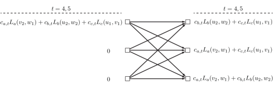
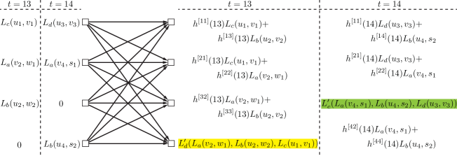
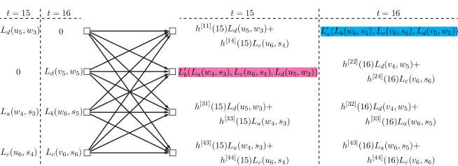
The transmission in phase is visually illustrated in Fig. 3. Note in the figure that in each time slot, the coloured quantity denotes the quantity which is available and undesired at the corresponding receiver by the end of that time slot. It only remains to deliver these coloured symbols, i.e., , , and to the pairs of receivers where they are desired as discussed above. This will be accomplished in phase through cooperation between the transmitters. The type of cooperation is determined by the channel feedback/cooperation assumption, that is, the assumptions (a)-(c). However, under each assumption, phase takes time slots, and thus, the overall achieved DoF will be . In the following, we present the phase under each assumption separately:
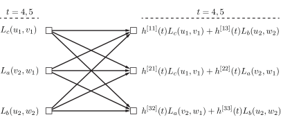
Phase (Full-duplex -user IC with Delayed CSIT):
Recall that in the first time slot, TX1 and TX2 respectively transmitted and , and TX3 was silent. According to full-duplex operation of the transmitters, TX1 receives a noisy version of and TX2 receives a noisy version of by the end of this time slot. This along with the delayed CSIT assumption enables both TX1 and TX2 to reconstruct a noisy version of , whose noise can be ignored as mentioned in Remark 1. Similarly, both TX2 and TX3 will reconstruct after the second time slot, and both TX3 and TX1 will reconstruct after the third time slot. Therefore, this phase takes time slots as follows:
Fourth time slot: The symbols , , and are transmitted by TX1, TX2, and TX3, respectively. Then, RX1 receives the following linear combination
and since it already has the undesired quantity , it can cancel it to obtain an equation solely in terms of and . Remember that both and are going to be delivered to RX1.
Also, RX2 receives
and RX3 receives
by the end of the fourth time slot. Similarly, RX2, having the undesired quantity , will obtain an equation in terms of two desired quantities and . Also, RX3 will similarly obtain an equation solely in terms of and .
Fifth time slot: This time slot is an exact repetition of the fourth time slot. Hence, since the channel coefficients are i.i.d. in time, by the end of this time slot, each receiver obtains a linearly independent equation in terms of its own two desired quantities, and thus, can decode both desired quantities.
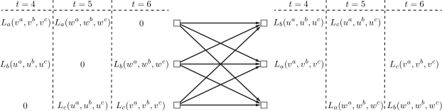
The above transmission scheme in phase is illustrated in Fig. 4a. This completes the delivery of the information symbols to their intended receivers in time slots, and thus, proves achievability of DoF with full-duplex delayed CSIT.
Phase (-user IC with Output Feedback):
With access to output feedback, the quantity is available at TX3 after the first time slot. Similarly, and are available at TX1 and TX2, respectively, after the second and third time slots. Hence, transmission of these symbols in phase can be done in two time slots using the same scheme explained above. The only difference is that here , , and are transmitted by TX1, TX2, and TX3 respectively, as shown in Fig. 4b.
Phase (-user IC with Shannon Feedback):
Under the Shannon feedback assumption, we argue that is available at all three transmitters after the first time slot as follows: TX3 obtains through the output feedback. On the other hand, TX1, having access to output feedback, obtains after this time slot. Then, since it also has access to delayed CSI and its own transmitted symbol , it can cancel the effect of from to obtain . Therefore, it can reconstruct using , , and the delayed CSI. Similarly, TX2 can reconstruct . Using a similar argument, and will be available at all three transmitters after the second and third time slots, respectively.
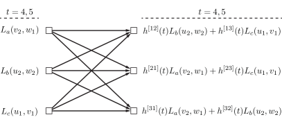
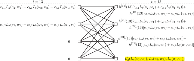
Recall that under each of the assumptions of full-duplex delayed CSIT and output feedback, to deliver , , and to their intended pairs of receiver in phase , we delivered two random linear combinations of them to each receiver. In those cases, each of these symbols was repeated by one of the transmitted in two time slots simultaneously. Here, we again deliver two random linear combinations of these three symbols to each receiver using another approach: two random linear combinations of , , and are transmitted by one of the transmitters, say TX1, in two time slots , while the rest of transmitters are silent. The coefficients of these combinations are generated offline and revealed to all receivers before the transmission begins. Hence, after two time slots, each receiver obtains two random linear combinations in terms of , , and , and will be able to remove its known undesired quantity and decode the other two desired quantities. Therefore, DoF is also achieved with Shannon feedback. The phase of the transmission scheme with Shannon feedback is depicted in Fig. 4c, where are the random coefficient.
III-B -user Interference Channel
Before proceeding with the -user IC, let us summarize the common ingredients of the transmission schemes proposed for the -user IC as follows:
-
(i)
The transmission is accomplished in consecutive phases (two phases in case of the -user IC).
-
(ii)
In each time slot of phase , fresh information symbols are transmitted by a subset of transmitters (with in case of the -user IC). The set of all receivers is then partitioned into two subsets and its complement (with in case of the -user IC). Each receiver in has a desired information symbol among the transmitted symbols, whereas the receivers in are not interested in decoding any transmitted symbol in this time slot.
-
(iii)
Each receiver in receives a piece of information (linear equation) in terms of its own desired symbol and interference symbol(s). Since there are more than one unknowns in the received equation, the receiver cannot resolve the equation for its desired symbol. It requires another linearly independent equations to resolve its own desired symbol (and the interference symbols).
-
(iv)
Each receiver in receives a piece of information (linear equation) in terms of undesired (interference) symbols. The linear equations received by any arbitrary receivers out of these receivers are, however, desired by all receivers in , in view of observation (iii) and the fact of the channel coefficients are i.i.d. across the channel nodes.
-
(v)
Let RX be one of these receivers. The linear combination received by RX, if retransmitted, provides each receiver in with a desired equation without causing any further interference at RX. In this sense, this linear combination can be considered as an “aligned interference” at RX because it only occupies one dimension in the received equation space of RX.
-
(vi)
These pieces of information are also available at a “subset of transmitters”, depending on the channel feedback/cooperation assumption. These transmitters can cooperate to retransmit these pieces of information in the subsequent phases of the transmission scheme (phase in case of the -user IC).
Along the direction highlighted by the above observations, we propose a -phase transmission scheme for the -user IC under each of the assumptions (a)-(c). As in the -user case, the proposed schemes for the -user IC have the same performance in terms of achievable DoF and achieve DoF under each assumption. We note that this is strictly greater than DoF which is the best known achievable DoF for the -user IC with delayed CSIT [19]. Since the three schemes are common in their phase , we present phase only once and then present the remaining phases separately under each assumption:
Phase (-user IC):
This phase takes time slots, during which information symbols
| (14) |
are fed to the system by the transmitters in parallel with phase of the scheme for the -user IC (see Section III-A). Figure 5 illustrates the transmission in phase for the -user IC.
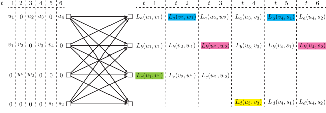
Time slots : TX1, TX2, and TX3 transmit information symbols exactly as in the -user case. TX4 is silent during the first time slots. Consequently, the linear combinations , , and which are respectively received by RX1, RX2, and RX3 need to be delivered to their respective pairs of receivers during the remaining phases. The availability of these quantities at TX1, TX2 and TX2 after the first time slots depends on the channel feedback/cooperation assumption and can be summarized as follows (see the corresponding phase in Section III-A for a detailed discussion):
-
•
Full-duplex delayed CSIT: is available at TX2 and TX3; is available at TX1 and TX3; and is available at TX1 and TX2.
-
•
Output feedback: , , and are available at TX1, TX2, and TX3, respectively.
-
•
Shannon feedback: , , and are available at all three transmitters TX1, TX2, and TX3.
The transmission in the remaining time slots of this phase is similarly proceeded by different subsets of out of the transmitters:
Time slots : TX1, TX2, and TX4 transmit fresh information symbols , while TX3 is silent. Similarly, , , and which are respectively received by RX1, RX2, and RX4 need to be delivered to their respective pairs of receivers during the remaining phases. These quantities are similarly available at subsets of based on the channel feedback/cooperation assumption.
Time slots : TX1, TX3, and TX4 transmit fresh information symbols , while TX2 is silent. Similarly, , , and which are respectively received by RX1, RX3, and RX4 need to be delivered to their respective pairs of receivers during the remaining phases. These quantities are similarly available at subsets of based on the channel feedback/cooperation assumption.
Time slots : TX2, TX3, and TX4 transmit fresh information symbols , while TX1 is silent. Similarly, , , and which are respectively received by RX2, RX3, and RX4 need to be delivered to their respective pairs of receivers during the remaining phases. These quantities are similarly available at subsets of based on the channel feedback/cooperation assumption.
Now, let us proceed with the remaining phases under each of the channel feedback/cooperation assumptions (a)-(c):
III-B1 Full-duplex -user IC with Delayed CSIT
Phase (Full-duplex -user IC with Delayed CSIT):
This phase takes time slots. In each time slot, transmitters simultaneously transmit three symbols generated during phase as follows:
Time slot : TX1, TX2, and TX3 respectively transmit , , and , while TX4 is silent. RX1 has and wishes to decode and . Hence, RX1 can obtain a linear combination solely in terms of and by cancelling from its received equation. Similarly, RX2 and RX3 each obtain a linear combination in terms of their desired pair of quantities. Thus, each of RX1, RX2, and RX3 requires another linearly independent equation to resolve its both desired quantities.
Now, consider the following linear combination received by RX4 over this time slot:
If we somehow deliver the above linear combination to RX1, it can obtain by cancelling . Since the channel coefficients are i.i.d. across the channel nodes, this linear combination is linearly independent of the equation RX1 has received during this time slot, and hence, it will enable RX1 to resolve its both desired quantities. Likewise, if we deliver to RX2 and RX3, each of them will be able to decode its both desired quantities. Thus, it is desired by RX1, RX2, and RX3, and will be delivered to them in phase .
We now argue that this linear combination will be available at TX1, TX2 and TX3 after this time slot. We indeed show that , , and will be available at these three transmitters, which together with the delayed CSIT assumption yields the desired result. But this immediately follows from the fact that each of TX1, TX2, and TX3 has two out of these three quantities, and thus, by the full-duplex operation, receives the third one during this time slot.
The transmission in the remaining time slots of phase is similarly done by other subsets of out of the transmitters:
Time slot : TX1, TX2, and TX4 respectively transmit , , and and the following linear combination which is received by RX3 will be desired by RX1, RX2, and RX4 and available at TX1, TX2, and TX4:
Time slot : TX1, TX3, and TX4 respectively transmit , , and and the following linear combination which is received by RX2 will be desired by RX1, RX3, and RX4 and available at TX1, TX3, and TX4:
Time slot : TX2, TX3, and TX4 respectively transmit , , and and the following linear combination which is received by RX1 will be desired by RX2, RX3, and RX4 and available at TX2, TX3, and TX4:
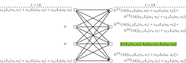
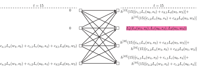
Figure 6 illustrates the transmission in phase for the -user IC with full-duplex delayed CSIT. The symbols , , , and will be delivered to their respective triples of receivers in phase .
Phase (Full-duplex -user IC with Delayed CSIT):
This phase takes time slots. In each time slot, , , , and are transmitted by TX1, TX2, TX3, and TX4, respectively. Each receiver has one of these quantities and requires the other three. By the end of this phase, each receiver will obtain three random linear combinations of its three desired quantities, and thus, will decode its desired quantities.
III-B2 -user IC with Output Feedback
Phase (-user IC with Output Feedback):
The above scheme for the phase under full-duplex delayed CSIT assumption can be used under output feedback assumption as well. The only difference is that in each of the time slots, the three corresponding symbols are transmitted using a different permutation of the same transmitters as follows:
Time slot : TX1, TX2, and TX3 respectively transmit , , and , while TX4 is silent. The linear combination will then be desired by RX1, RX2, and RX3 and will be available at TX4 after this time slot via output feedback.
Time slot : TX1, TX2, and TX4 respectively transmit , , and , while TX3 is silent. The linear combination will be desired by RX1, RX2, and RX4 and available at TX3.
Time slot : TX1, TX3, and TX4 respectively transmit , , and , while TX2 is silent. The linear combination will be desired by RX1, RX3, and RX4 and available at TX2.
Time slot : TX2, TX3, and TX4 respectively transmit , , and , while TX1 is silent. The linear combination will be desired by RX2, RX3, and RX4 and available at TX1.
The symbols , , , and will be delivered to their respective triples of receivers in phase .
Phase (-user IC with output feedback):
This phase takes time slots. In each time slot, the symbols (linear combinations) , , , and are transmitted by TX1, TX2, TX3, and TX4, respectively. Similar to the full-duplex delayed CSIT, by the end of this phase, each receiver will decode its desired symbols.
III-B3 -user IC with Shannon Feedback
Phase (-user IC with Shannon Feedback):
This phase takes time slots as follows:
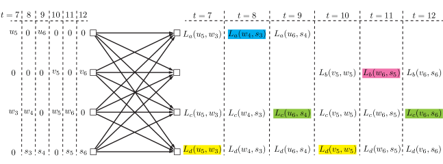
Time slot : Recall from phase that , , and are all available at each of TX1, TX2, and TX3. We also note that if we deliver two random linear combinations of these three quantities to RX1, RX2, and RX3, then each of them will be able to decode its two desired quantities out of these three quantities. Hence, two random linear combinations of them with offline generated coefficients are simultaneously transmitted by two transmitters out of TX1, TX2, and TX3 (say, TX1 and TX2). Then, each of RX1, RX2, and RX3 receives one linear equation in terms of , , and and requires another random linear combination to resolve both desired quantities. Thus, the linear combination which is received by RX4 is desired by each of the other three receivers. Also, this linear combination is available at TX4 through the output feedback and is available at the other transmitters, since they all have , , and .
The remaining time slots are similarly dedicated to transmission of other linear combinations as follows:
Time slot : Two random linear combinations of , , and are transmitted by TX4 and TX1. The linear combination which is received by RX3 is desired by each of the other three receivers, and is available at all transmitters.
Time slot : Two random linear combinations of , , and are transmitted by TX3 and TX4. The linear combination which is received by RX2 is desired by each of the other three receivers, and is available at all transmitters.
Time slot : Two random linear combinations of , , and are transmitted by TX2 and TX3. The linear combination which is received by RX1 is desired by each of the other three receivers, and is available at all transmitters.
The transmission in phase for the -user IC with Shannon feedback is illustrated in Fig. 7.
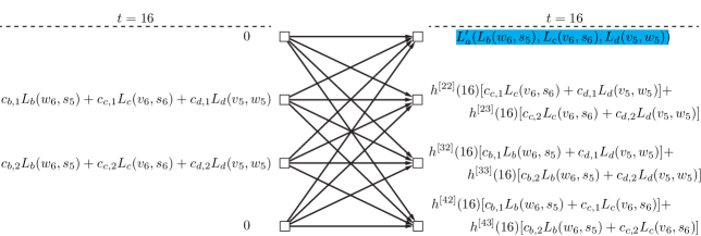
Phase (-user IC with Shannon feedback):
Over time slots, one of the transmitters, say TX1, transmits random linear combinations of , , , and , and thus, each receiver will decode its desired symbols by the end of this phase.
Our achievable DoF for the -user IC under each of the feedback/cooperation assumptions will then be .
Remark 2
Although the proposed transmission schemes for the -user and -user IC achieve the same DoF under each of the channel feedback/cooperation assumptions, this is not generally the case as it will be seen later. Indeed, for , the proposed transmission schemes achieve strictly different DoFs under different feedback/cooperation assumptions.
IV Illustrative Examples: X Channel
In this section, we illustrate our transmission schemes for the and X channel under each of the channel feedback/cooperation assumptions (a)-(c). Before proceeding with the details of the transmission schemes, let us introduce a notation which is exclusively used in this section:
Notation 3
The symbols , , and denote information symbols of TX1, TX2, and TX3, respectively, all intended for RX1. Similarly, , , and denote information symbols intended for RX2, and , , and are all intended for RX3.
We also use the same notations for the linear combinations and their colouring as defined in Notation 2.
IV-A X Channel
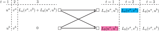
It is already known that X channel can achieve DoF with output feedback [15]. This is indeed the DoF of -user MISO broadcast channel with Shannon feedback [12], which is also an upper bound to the DoF of X channel under each of the assumptions (a)-(c). Hence, the DoF of X channel with output feedback or with Shannon feedback is equal to . In this section, we show that X channel has the same DoF under the full-duplex delayed CSIT assumption as well. The transmission scheme operates in parallel with scheme proposed in [12] for the -user MISO broadcast channel and employed in [15] for the X channel with output feedback. It is a two-phase transmission scheme depicted in Fig. 8, wherein the fresh information symbols are transmitted over the channel in the first phase and delivery of the symbols to their intended receivers is completed in the second phase. In particular, information symbols are delivered in time slots as follows:
Phase (Full-duplex X Channel with Delayed CSIT):
This phase takes time slots to transmit information symbols as follows:
First time slot: The symbols and are transmitted by TX1 and TX2, respectively. Ignoring the noise, RX1 will receive a linear equation
| (15) |
in terms of desired information symbols, and hence, requires another linearly independent equation to resolve them. Simultaneously, RX2 receives another linear equation, namely,
| (16) |
in terms of and . Since the channel coefficients are i.i.d. across the channel nodes, is linearly independent of almost surely. Therefore, if we deliver to RX1 it will be able to decode both and . On the other hand, according to full-duplex operation of the transmitters, both TX1 and TX2 will have both and , and by the delayed CSIT assumption, they can reconstruct after this time slot.
Second time slot: Similarly, and are transmitted respectively by TX1 and TX2. Then, the linear combination
| (17) |
which is received by RX1 will be desired by RX2 and available at both TX1 and TX2.
Therefore, it only remains to deliver and to RX1 and RX2 respectively. This is accomplished in one time slot in phase :
Phase (Full-duplex X Channel with Delayed CSIT):
Third time slot: One of the transmitters, say TX1, transmits , while the other transmitter is silent. RX1 receives this linear combination, and it can cancel which it already has, to obtain the desired quantity . Similarly, RX2 can cancel to obtain .
IV-B X Channel
For this channel, we achieve DoF with full-duplex delayed CSIT. We also achieve DoF and DoF with output feedback and Shannon feedback, respectively. In the following, we show the achievability of each of the above DoFs:
IV-B1 Full-duplex X Channel with Delayed CSIT
We propose a -phase transmission scheme which delivers information symbols in time slots, and thus, achieves DoF as follows:
Phase (Full-duplex X Channel with Delayed CSIT):
This phase takes times slots to transmit information symbols.
Time slots : Only TX1 and TX2 transmit information symbols, and TX3 is silent. In particular, for each pair of receivers, TX1 and TX2 use time slots to transmit information symbols exactly as in phase of the scheme proposed above for the full-duplex X channel with delayed CSIT.
Time slots : Similarly, another information symbols are now transmitted by TX1 and TX3, while TX2 is silent.
The transmission in this phase is illustrated in Fig. 9. Each coloured linear combination in the figure is available at one receiver and desired by another receiver, and will also be reconstructed by two of the transmitters after its corresponding time slot. For example, is available at RX2 and desired by RX1, and will be reconstructed by TX1 and TX2 after the first time slot. Now, it only remains to deliver the following linear combinations to their respective pairs of receivers (as discussed in phase of the full-duplex X channel with delayed CSIT):
| (18) | |||
| (19) |
This will be accomplished during the remaining phases of the transmission scheme.

Phase (Full-duplex X Channel with Delayed CSIT):
This phase takes time slots to transmit the linear combinations indicated in Eqs. 18 and 19 by TX1 and TX2 as follows. TX3 is silent in this phase.
Time slot : TX1 and TX2 transmit and , respectively, while TX3 is silent. By the end of this time slot, RX1 obtains a linear combination in terms of the (desired) quantities (after cancelling the known quantities). Hence, it requires another linearly independent combination of the quantities to decode both of them. Similarly, RX2 obtains a linear combination of the (desired) quantities and needs another linearly independent combination of them to decode both. Now, one can easily verify that the linear combination
| (20) |
received by RX3 during this time slot, is linearly independent of the linear combination received by each of RX1 and RX2. Therefore, if we deliver this linear combination to both RX1 and RX2, each of them will be able to decode its both desired or quantities. On the other hand, by the delayed CSIT assumption, is available at TX1 as well (note that TX1 has both transmitted linear combinations).
The next two time slots are similarly dedicated to the other pairs of receivers:
Time slot : TX1 and TX2 transmit and , respectively. Now, each of RX1 and RX3 receives a desired linear combination and the linear combination
| (21) |
received by RX2 during this time slot, will be desired by both RX1 and RX3. This linear combination is also available at TX1 after this time slot.
Time slot : TX1 and TX2 transmit and , respectively. Each of RX2 and RX3 receives a desired linear combination and the linear combination
| (22) |
received by RX1 during this time slot, will be desired by both RX2 and RX3. This linear combination is also available at TX1 after this time slot.
In summary, the linear combinations , , and each are available at one receiver and desired by the other two receivers, and all of them are available at TX1. They will be delivered to their respective pairs of receivers in phase .
Phase (Full-duplex X Channel with Delayed CSIT):
Time slots : In each time slot, a random linear combination of , , and is transmitted by TX1, while the rest of transmitters are silent. It can be easily verified that after these two time slots, each receiver will be able to decode its both desired quantities.
IV-B2 X Channel with Output Feedback
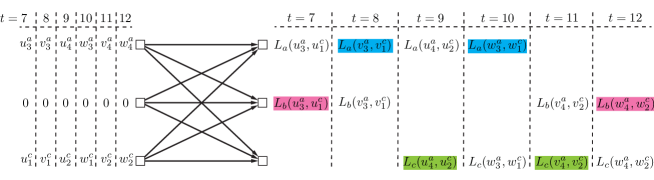
Our transmission scheme for this channel is a -phase scheme wherein information symbols are delivered to the receivers in time slots, yielding DoF, as illustrated in Fig. 10 and elaborated on in the following:
Phase ( X Channel with Output Feedback): This phase has time slots. Each time slot is dedicated to transmission of information symbols intended for one of the receivers:
First time slot: The information symbols , , and , all intended for RX1, are transmitted by TX1, TX2 and TX3, respectively. By the end of this time slot, RX1 receives linear combination of the three desired symbols and requires two extra linearly independent equations to resolve all three symbols. RX2 receives the linear combination which is linearly independent of , and thus, is desired by RX1. Similarly, the linear combination received by RX3 is desired by RX1. On the other hand, (resp. ) will be also available at TX2 (resp. TX3) through the output feedback.
The second and third time slots are similarly dedicated to RX2 and RX3, respectively:
Second time slot: The information symbols , , and , all intended for RX2, are transmitted by TX1, TX2 and TX3, respectively. Similarly, and , received by RX1 and RX3 and available at TX1 and TX3 through the output feedback, will be desired by RX1 after this time slot.
Third time slot: The information symbols , , and , all intended for RX3, are transmitted by TX1, TX2 and TX3, respectively. Similarly, and , received by RX1 and RX2 and available at TX1 and TX2 through the output feedback, will be desired by RX3 after this time slot.
Therefore, to deliver the transmitted information symbols to their intended receivers, it suffices to
-
(i)
deliver and to RX1;
-
(ii)
deliver and to RX2;
-
(iii)
deliver and to RX3.
This will be done in phase .
Phase ( X Channel with Output Feedback):
This phase takes time slots. Each time slot is dedicated to a pair of receivers as follows:
Fourth time slot: Over this time slot, which is dedicated to RX1 and RX2, and are respectively transmitted by TX1 and TX2, while TX3 is silent. After this time slot, RX1 obtains the desired linear combination by cancelling the known undesired linear combination . Similarly, RX2 obtains its own desired linear combination by cancelling .
Fifth time slot: The quantities and are transmitted by TX1 and TX3, while TX2 is silent. Then, each of RX1 and RX3 similarly obtains its desired quantity.
Sixth time slot: The quantities and are transmitted by TX2 and TX3, while TX1 is silent. Then, each of RX2 and RX3 similarly obtains its desired quantity.
IV-B3 X Channel with Shannon Feedback
Our transmission scheme for this channel has two rounds of operation, during which information symbols are delivered to the receivers in time slots as follows:
Round ( X Channel with Shannon Feedback):
The first round consists of two phases. Phase takes time slots to transmit information symbols exactly as in phase of the scheme proposed above for the same channel with output feedback. Before proceeding with phase , one notes that TX1 after the first time slot will obtain the linear combination
| (23) |
through the output feedback. Since TX1 has access to delayed CSI as well (Shannon feedback assumption), it can cancel its own transmitted symbols to obtain
| (24) |
which is a linear combination of and . TX1 knows the coefficients and of this linear combination. Similarly, TX2 will obtain after the second time slot using Shannon feedback.
In phase , over one time slot, TX1 and TX2 transmit and , while TX3 is silent. Hence, and are delivered to RX2 and RX1, respectively (as in the phase of the scheme proposed with output feedback). Now, TX1 will obtain since it has access to Shannon feedback and its own transmitted quantity i.e., . Therefore, by cancelling from , TX1 will obtain
| (25) |
which is another linear combination of and . Hence, using Eqs. 24 and 25, TX1 will be able to decode both and . Thereby, having access to delayed CSI, TX1 can reconstruct . Likewise, TX2 will be able to decode both and , and hence, can reconstruct .
In summary, after these time slots, it only remains to
-
(i)
deliver to RX1;
-
(ii)
deliver to RX2;
-
(iii)
deliver and to RX3.
On the other hand, TX1 has access to by above argument and has access to using output feedback. Similarly, TX2 has access to and . Hence, it suffices to deliver the following two linear combinations to their respective pairs of receivers:
| (26) | ||||
| (27) |
Before proceeding with the second round, we repeat the above procedure two more times and transmit another fresh information symbols, namely , in another time slots. However, in the first repetition, and are transmitted by TX1 and TX3 in phase , and it will suffice to deliver the following two linear combinations to their respective pairs of receivers:
| (28) | ||||
| (29) |
Similarly, in the second repetition, and are transmitted by TX2 and TX3 in phase , and it will suffice to deliver the following two linear combinations to their respective pairs of receivers:
| (30) | ||||
| (31) |
Up to this point, we have spent time slots, transmitted information symbols. Now, we need to to deliver the above linear combinations to their respective pairs of receivers. This will be done in the second round.
Round ( X Channel with Shannon Feedback):
This round takes time slots, i.e., . During the first time slots the above linear combinations are transmitted over the channel. Each time slot is dedicated to a pair of receivers as follows:
Time slot : TX1 and TX2 respectively transmit and (both to be delivered to RX1 and RX2 according to Eqs. 28 and 30), while TX3 is silent. Then, using an argument similar to the phase of the transmission scheme proposed for the full-duplex X channel with delayed CSIT, RX1 (resp. RX2) receives an equation in terms of the (desired) linear combinations and (resp. and ). Also, the equation
| (32) |
received by RX3 in this time slot will be desired by both RX1 and RX2. It can also be easily verified that can be reconstructed by TX1 due to Shannon feedback.
Time slot : TX1 and TX3 respectively transmit and , both desired by RX1 and RX3, while TX2 is silent. Then, the linear combination
| (33) |
received by RX2 will be desired by both RX1 and RX3 and can be reconstructed by TX1 using Shannon feedback.
Time slot : TX2 and TX3 respectively transmit and , both desired by RX2 and RX3, while TX1 is silent. Then, the linear combination
| (34) |
received by RX1 will be desired by both RX2 and RX3 and is received by TX1 using Shannon feedback (output feedback).
During the last time slots of this round, the linear combinations , and , and are delivered to their intended pairs of receivers:
Time slots : Two random linear combinations of , and , and are transmitted by TX1, while the rest of transmitters are silent. Each receiver will then be able to decode its two desired linear combinations.
The achieved DoF is therefore equal to .
V Main Results
The main results of this paper are summarized in the following six theorems. The proof of each theorem is provided in its respective section.
V-A Full-duplex Transmitter Cooperation and Delayed CSIT
Theorem 1
The -user () SISO Gaussian interference channel with delayed CSIT and full-duplex transmitters can achieve degrees of freedom almost surely, where is given by
| (35) |
Proof:
See Section VI-A. ∎
Theorem 2
The SISO Gaussian X channel with delayed CSIT and full-duplex transmitters can achieve degrees of freedom almost surely, where is given by
| (36) |
Proof:
See Section VI-B. ∎
V-B Output Feedback
Theorem 3
The -user () SISO Gaussian interference channel with output feedback can achieve degrees of freedom almost surely, where is given by
| (37) |
with and defined as
| (38) | ||||
| (39) |
Proof:
See Section VII-A. ∎
Theorem 4
The SISO Gaussian X channel with output feedback can achieve degrees of freedom almost surely222The result of this theorem has been simultaneously and independently reported in [31].
Proof:
See Section VII-B. ∎
V-C Shannon Feedback
Theorem 5
The -user () SISO Gaussian interference channel with Shannon feedback can achieve degrees of freedom almost surely, where is given by
| (40) |
with given by 62, and given by
| (41) |
Proof:
See Section VIII-A. ∎
Theorem 6
The SISO Gaussian X channel with Shannon feedback can achieve degrees of freedom almost surely, where is given by
| (42) |
Proof:
See Section VIII-B. ∎
V-D Some Comments
Before proceeding with the proof details, we highlight some key features of our proposed transmission schemes through the following observations:
-
1.
For each of IC and X channel and under each of the feedback/cooperation assumptions, a “multi-phase” transmission scheme is proposed.
-
2.
During phase , in each time slot, fresh information symbols are transmitted by a subset of transmitters such that:
-
(i)
Each receiver receives a number of linear combinations of its own desired information symbols (and possibly some interference symbols). The received linear combinations are not enough to resolve all desired symbols (possibly including some interference symbols).
-
(ii)
Each receiver also receives some linear combinations solely in terms of undesired information symbols. However, these linear combinations are desired by some other receivers in view of observation (2i). On the other hand, by the end of phase , each of these linear combinations will be also available at a subset of transmitters based on the feedback/cooperation assumption.
-
(i)
-
3.
During the remaining transmission phases, the transmitters deliver the linear combinations mentioned in observation (2ii) to the receivers where they are desired:
-
(i)
Phase , , takes some linear combinations as its inputs. Each of these linear combinations is available at a subset of transmitters and is desired by a subset of cardinality of receivers (and is at most available at one unintended receiver as well).
-
(ii)
During phase , the input linear combinations are transmitted over the channel such that each intended receiver obtains “part” of the information required to decode the input linear combinations. The rest of information required by each intended receiver (to decode all its desired linear combinations) is obtained by a subset of unintended receivers. These pieces of information will be delivered to the intended receivers during phases .
-
(iii)
In specific, the mentioned pieces of information (or a mixture of them) is now desired by a subset of cardinality of receivers, and is available at a subset of transmitters and at most one unintended receiver. These linear combinations constitute the inputs of phase .
-
(iv)
The transmission continues until the last phase. The input of the last phase is the linear combinations which are desired by all receivers (except for at most one unintended receiver where the linear combination is already available). These linear combinations are delivered to their intended receivers by an appropriate number of transmissions.
-
(i)
-
4.
Under the full-duplex delayed CSIT assumption, for both IC and X channel, only two transmitters are simultaneously active in each time slot of phase .
-
5.
Under the output feedback and Shannon feedback assumptions, in each time slot of phase ,
-
(i)
for the X channel, all transmitters are simultaneously active.
-
(ii)
for the IC, the number of active transmitters is a function of the number of users.
-
(i)
-
6.
Under the Shannon feedback assumption, the schemes proposed for both IC and X channel operate in two rounds: The first round follows the scheme proposed for the output feedback. However, as the scheme proceeds, each transmitter obtains more information about the symbols of the other transmitters using Shannon feedback. Eventually, each transmitter will be able to decode some information symbols of the other transmitters. Then, the transmission scheme will move on to the second round, where more transmitters can cooperate in the rest of transmissions.
Here, we introduce some notations which are widely used in the subsequent proof sections, namely, Sections VI, VII and VIII:
Notation 4
In the -user IC and X channel, denotes a subset of cardinality of transmitters (or receivers), , where is the index set of all transmitters (or receivers). In the X channel, subsets of cardinality and of transmitters and receivers are denoted by and , respectively, where and are respectively the index sets of all transmitters and all receivers and , . A coded symbol which is available at all transmitters TXi, , and all receivers RX, , and is intended to be decoded at all receivers RXj, , is denoted by . The superscripts “(t)” and “(r)” may be omitted whenever it is clear. If , the mentioned symbol is denoted by and is called an order- symbol.
VI SISO Interference and X Channels with Full-duplex Transmitter Cooperation and Delayed CSIT
In this section, we investigate the impact of full-duplex transmitter cooperation on the DoF of the -user IC and X channel with delayed CSIT. We will demonstrate how transmitters can exploit their knowledge about each other’s messages (attained through the full-duplex cooperation) combined with the delayed CSIT to achieve a higher DoF compared to the non-cooperative delayed CSIT. In specific, we prove Theorems 1 and 2 as follows:
VI-A Proof of Theorem 1
Our transmission scheme for the -user IC consists of phases as follows:
Phase (Full-duplex -user IC with Delayed CSIT): In this phase, fresh information symbols are fed to the channel as follows: For every subset , spend time slots to transmit fresh information symbols by as follows:
In the first time slot, TX and TX transmit and , respectively, the rest of transmitters are silent. Hence, ignoring the noise, RX and RX each receive one linear equation in terms of and by the end of the first time slot. Therefore, if we deliver a linearly independent equation in terms of and to both RX and RX, each of them will be able to decode both transmitted symbols (desired and interference). This linearly independent equation is indeed the linear combination received by RX during this time slot. On the other hand, according to full-duplex operation of the transmitters, both TX and TX will have both and by the end of the first time slot. This along with the delayed CSIT assumption enables both TX and TX to reconstruct . Thus, according to Notation 4, one can define
| (43) |
Similarly, the second and third time slots are described as follows:
-
•
Second time slot: TX and TX transmit and , respectively. The symbol will be accordingly generated after this time slot.
-
•
Third time slot: TX and TX transmit and , respectively. The symbol will be accordingly generated after this time slot.
Therefore, information symbols are transmitted in time slots and symbols of type , , are generated by the end of phase . We denote by , , our achievable DoF for transmission of symbols of type , , over the -user IC with full-duplex delayed CSIT. The achieved DoF is then calculated as
| (44) |
Phase , (Full-duplex -user IC with Delayed CSIT): For , define
| (45) | ||||
| (46) |
where , , is the least common multiplier of and . This phase takes symbols , , transmits them over the channel in time slots, and generates symbols of type , , where is defined as
| (47) |
Fix a subset , and a subset . During time slots, each TX, , transmits a random linear combination of , , (with ) in each time slot. Therefore, a total of symbols are transmitted in time slots. We note that the random coefficients of these linear combinations are generated offline and shared with all nodes. Now, the following observations are important:
-
(i)
RXj, , wishes to decode the symbols , . Since it has all the symbols , by canceling them, it will obtain equations out of its received equations, solely in terms of its desired symbols.
-
(ii)
TXi, , has all the transmitted symbols except for . According to the full-duplex operation, it will obtain random linear combinations of these symbols after canceling its known symbols, and since , it can decode all of them.
-
(iii)
RX, , receives linear equations in terms of all transmitted symbols. If we deliver these linear combinations to RXj, , it will be able to cancel its undesired part as argued in observation (i) and obtain equations solely in terms of its desired symbols. On the other hand, in view of observation (ii) and according to the delayed CSIT assumption, TXi, , can reconstruct all these linear combinations by the end of the time slots. Thus, the linear combinations received by RX, , are denoted by . After delivering these symbols to RXj, , it will be provided with a total of linear combinations in terms of its desired symbols. Also, it is easy to show that these linear combinations are linearly independent almost surely, and hence, can be solved for the desired symbols.
Since there are choices of and choices of for each , the achieved DoF equals
| (48) |
Phase (Full-duplex -user IC with Delayed CSIT): During consecutive time slots, TXi, , repeats the symbol (with ). It is easily verified that, in each time slot, each receiver obtains a linear combination of its desired symbols. Hence, after time slots, every receiver will be able to decode all its desired symbols. One then can write
| (49) |
VI-B Proof of Theorem 2
For the general SISO X channel, a -phase transmission scheme is proposed wherein the information symbols are transmitted in the first phase towards generation of higher order symbols during the subsequent phases. The order- symbols will be finally delivered to all receivers in phase .
Phase (Full-duplex X Channel with Delayed CSIT): Fix . For any , TX and TX transmit four fresh information symbols , , , and in two time slots as follows (we have ignored the indices of symbols for ease of notations): over the first time slot, TX and TX respectively transmit , , both intended for RX. After this time slot, the linear combination , which has been received by RX, is available at TX and TX due to full-duplex operation of the transmitters and delayed CSIT, and is desired by RX to be able to decode and . Hence, it is denoted as . Similarly, over the second time slot, TX and TX respectively transmit , , both intended now for RX, and the symbol is generated. It is easily verified that is desired by both RX and RX. Hence, one can define the following order- symbol:
| (50) |
By the end of this phase, fresh information symbols are transmitted in time slots and order- symbols are generated, which will be delivered to their corresponding pairs of receivers during the rest of the transmission scheme. The achieved DoF is then calculated as
| (51) |
where denotes our achievable DoF for transmission of order- symbols of type over the full-duplex SISO X channel with delayed CSIT.
Phase , (Full-duplex X Channel with Delayed CSIT): Consider the following distinct cases:
-
(i)
:
In this case, order- symbols of type are transmitted over the channel. Fix a subset , and a subset . Note that since , both subsets exist. All transmitters TXj, , are silent, while the transmitters TX, , simultaneously transmit as follows: For every subset , spend one time slot to transmit by , , where for . Every RXj, , receives one linear equation in terms of desired symbols, and thus, requires extra independent equations to resolve all the symbols. It is easy to see that the equation received by RXj, , is linearly independent of the equation received by each RXj, , and hence, is desired by all of them. On the other hand, every TX, , knows exactly symbols out of the transmitted symbols, and thus, obtains the last one using the full-duplex operation by the end of this time slot. Hence, TX, , having access to all the transmitted symbols and the delayed CSI, can reconstruct the linear combinations received by all receivers by the end of this time slot. In particular, one can denote the linear combination received by RXj, , as .
Now, we have the following observation: For any subset , consider the symbols , , as defined above. Each receiver RXj, , has exactly one of these symbols and requires the other . Therefore, if we deliver random linear combinations of these symbols to all receivers RXj, , each of them will be provided with random linear combinations of desired unknowns, and thus, will resolve all of them. Hence, these random linear combinations can be denoted as . These order- symbols will be delivered to their corresponding receivers during the rest of the transmission scheme. We denote by , , our achievable DoF for transmission of order- symbols of type over the full-duplex SISO X channel with delayed CSIT. Since there are choices for , choices for , and choices for , the achieved DoF is calculated as
(52) -
(ii)
:
In this case, order- symbols of type are transmitted over the channel. Since and , we have , and thus, these symbols can be optimally transmitted over the channel using the scheme proposed in [12] for transmission of order- symbols over an MISO broadcast channel with delayed CSIT when (cf. [12] Section III-C). We note that, in this case, the transmitters do not use their full-duplex capabilities, since enough number of transmitters already know the order- symbols which are going to be transmitted over the channel. Here, we denote by , , the achievable DoF for transmission of order- symbols of type over the full-duplex SISO X channel with delayed CSIT. Hence, the following recursion holds (cf. Eq. (27) in [12]):
(53) -
(iii)
:
-
(iv)
:
In this case, order- symbols of type are transmitted over the channel without operating in the full-duplex mode using the scheme proposed in [12] for transmission of order- symbols over an MISO broadcast channel with delayed CSIT (see [12] Section VI-B), and the following DoF is achieved (cf. Eq. (39) in [12]):
| (54) |
where (resp. ), in this case, denotes our achievable DoF for transmission of symbols of type (resp. ) over the full-duplex SISO X channel with delayed CSIT.
To summarize our achievable results for the above cases, for , we define
| (55) | ||||
| (56) |
and denote by our achievable DoF for transmission of order- symbols of type over the full-duplex SISO X channel with delayed CSIT. Then, it is easy to see from Eqs. 51, 52, 53 and 54 that our achievable DoF satisfies the following recursive equation:
| (57) |
Phase (Full-duplex X Channel with Delayed CSIT):
In this phase, the symbols of type are delivered to all receivers by simple transmission of one symbol per time slot by one of the transmitters (which has access to that symbol). Therefore,
| (58) |
VII SISO Interference and X Channels with Output Feedback
In this section, we investigate the impact of output feedback on the DoF of the -user IC and X channel. As defined in Section II, we assume that output of each receiver is fed back to its paired transmitter. This provides each transmitter with “some” information about the other transmitters’ messages, which enables the transmitters to cooperate in their subsequent transmissions. Recall that in our achievable schemes for the full-duplex IC and X channel with delayed CSIT, described in Section VI, each transmitter acquired pure symbols of the other transmitters via full-duplex cooperation in order to reconstruct the linear combinations received by the receivers. The number of simultaneously active transmitters was restricted in each time slot such that each active transmitter can obtain a pure symbol transmitted by one of the others. For instance, in phase of the scheme, only two transmitters per time slot were allowed to simultaneously transmit over the channel. In contrast, when the output feedback is available, the linear combination received by each receiver will become readily available at one of the transmitters, and thus, the restriction on the number of simultaneously active transmitters is relaxed, providing for a higher level of transmitter cooperation and interference alignment. The rest of this section presents proofs of Theorems 3 and 4.
VII-A Proof of Theorem 3
Our transmission scheme for the -user IC with output feedback consists of phases as follows, where the integer , , will be determined later:
Phase (-user IC with Output Feedback): For every subset , and every subset , in one time slot, each TXi, , transmits a fresh information symbol . Then, if we deliver linearly independent combinations of the transmitted symbols to RXi, , it will be able to decode all the transmitted symbols. Thus, the equation received by RXj, , which will be available at TXj via the output feedback, is desired by all the receivers RXi, . Hence, they can be denoted as , .
Therefore, information symbols are transmitted in time slots and symbols are generated by the end of phase . Denoting by our achievable DoF for transmission of symbols , , over the -user IC with output feedback, the achieved DoF is equal to
| (59) |
Phase , (-user IC with Output Feedback): This phase feeds symbols of type , , to the channel in time slots, and generates symbols of type , . In specific, for every subset , and every subset , during time slots, every TXi, , transmits random linear combinations of symbols . Each RXj, , wishes to decode the symbols , . Also, RXj, , after removing from its received equations, obtains linear equations solely in terms of its desired symbols. If we deliver the linear equations received by RX, , to RXj, , it will obtain another linear equations solely in terms of its desired symbols. Since these equations will be available at TX, , via the output feedback, they are denoted as . Therefore, RXj, , will have (linearly independent) equations in terms of its desired symbols, and can solve them for its desired symbols.
Finally, since the number of input symbols, spent time slots, and output symbols of this phase are equal to those of phase in the proposed transmission scheme for the full-duplex -user IC with delayed CSIT described in proof of Theorem 1, the achieved DoF for phase satisfies the same recursive equation, i.e., 48:
| (60) |
Phase (-user IC with Output Feedback): During consecutive time slots, TXi, , repeats the symbol . Therefore, each receiver receives linear combination of its desired symbols, and thus, will be able to decode all its desired symbols. Hence,
| (61) |
It is shown in Appendix A that the solution to recursive Eq. (60) with initial condition (61) is given by
| (62) |
Substituting 62 for in 59, we get
| (63) |
where is defined by 39. Now, we choose such that given in 63 is maximized. In other words,
| (64) |
where is defined as
| (65) |
By taking the derivative of with respect to , it can be shown that the solution to the maximization problem is given by 38. Thus, since is a continuous and concave function of , the solution to the maximization problem (64) is either or , depending on which yields a greater , i.e.,
| (66) |
which in view of Eqs. 65 and 63 completes the proof. Figure 11 shows the achievable DoF for different values of together with the optimized achievable DoF, i.e., , for .
VII-B Proof of Theorem 4
We propose a transmission scheme which consists of main phases as follows:
Phase ( X Channel with Output Feedback): For every , spend one time slot to transmit the fresh information symbols , , , respectively by TX1, TX2, , TXK, all intended for RXj. By the end of this time slot, RXj has received one linear combination of all desired symbols. Therefore, if the linear combinations received by RX, , are delivered to RXj, it can decode all the symbols. On the other hand, according to the output feedback, the linear combination received by RX, , will be available at TX after this time slot. Hence, they can be denoted as , . Therefore, after time slots, symbols , , , will be generated. These symbols will be delivered to their respective receiver during the next phase.
Phase ( X Channel with Output Feedback): This phase takes time slots to deliver the symbols generated in phase as follows: For any subset , spend one time slot to transmit and by TXj and TX, respectively, while the other transmitters are silent. After this time slot, each of RXj and RX can decode its desired symbol by canceling the interference symbol which it already has. The achieved DoF is then equal to
| (67) |
completing the proof.
VIII SISO Interference and X Channels with Shannon Feedback
With Shannon feedback, each transmitter has access to all observations made by its paired receiver, i.e., the channel output and all the channel coefficients, with some delay. Moreover, it has access to its own transmitted symbols. If a receiver wants to decode, say, symbols (some of which might be interference), it requires linearly independent equations in terms of the symbols. However, the key observation is that after delivering required equations to a receiver, its paired transmitter having access to Shannon feedback and its own transmitted symbol (which is one of the symbols), will be able to decode all the remaining symbols. Then, using the delayed CSIT, it will be able to reconstruct the last (yet undelivered) linear combination, and hence, to cooperate for its delivery. This allows for achieving higher DoFs compared to what we achieved in Sections VI and VII. The following two subsections offer proofs of Theorems 5 and 6.
VIII-A Proof of Theorem 5
Our achievable scheme for the -user IC with Shannon feedback has two rounds of operation:
Round (-user IC with Shannon Feedback): In this round, the transmitters use only the output feedback in parallel with the scheme proposed in proof of Theorem 3. In specific, during phase , for every subset , every subset , and every , in one time slot, each TXi, , transmits a fresh information symbol . The integer , , will be determined later. The linear combination received by RXj, , which will be available at TXj via the output feedback, is desired by every RXi, .
Now, TXi, , using Shannon feedback and having , obtains an equation in terms of the symbols , . We deliver the linear combinations available at the receivers RXj, , to every RXi, , using the scheme proposed in proof of Theorem 3. Meanwhile, TXi using Shannon feedback and having , will obtain another linearly independent combinations of , , and hence, can decode all of them. Thereby, it can reconstruct the linear combination available at RX, which is still required by every RXi, . Hence, this linear combination will be denoted as .
We note that, for every subset , and every subset , we have generated symbols , . Since every RXi, , needs exactly out of these symbols, random linear combinations of these symbols are desired by each RXi, , and can be denoted as . They will be delivered during round of the transmission scheme. The achieved DoF is therefore given by
| (68) |
where
| (69) |
and denotes our achievable DoF for transmission of the symbols of type over the -user IC with Shannon feedback.
Round (-user IC with Shannon Feedback): This round consists of phases described as follows:
Phase , (-user IC with Shannon Feedback): In this phase, symbols of type are fed to the channel and symbols of type are generated as follows: Fix a subset , where , , is defined in 46. For any , spend one time slot to transmit by arbitrary transmitters out of . Then, RXj, , requires extra equations to resolve all the transmitted symbols. Thus, the linear combination received by RX, , which will be available at TX via the output feedback, is desired by every RXj, . On the other hand, every TXj, , having access to all the transmitted symbols and delayed CSI, can reconstruct this linear combination. Therefore, it is denoted as .
Now, for any subset , consider symbols , . It is easy to see that random linear combinations of these symbols are desired by each RXi, , and can be denoted as . The achieved DoF equals
| (70) |
Phase (-user IC with Shannon Feedback): In this phase, one symbol per time slot is transmitted by an arbitrary transmitter. Hence,
| (71) |
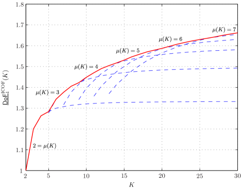
It is shown in Appendix C that the solution to the recursive Eq. (70) with initial condition (71) is given by 41. Therefore, the proof is complete in view of 68 and the fact that is chosen to maximize . The achievable DoF for different values of and the optimized achieved DoF are plotted in Fig. 12 for .
VIII-B Proof of Theorem 6
Our transmission scheme for the X channel with output feedback operates in rounds:
Round ( X Channel with Shannon Feedback): This round has phases in parallel with the scheme proposed in proof of Theorem 4 for the same channel with output feedback. In particular, in phase , fresh information symbols , , are transmitted over the channel during time slots in the same way as the phase of the scheme proposed in proof of Theorem 4, and symbols , , are generated correspondingly. After time slot , TXj, having access to its own transmitted symbol and Shannon feedback, will obtain a linear combination of the symbols , . Therefore, if TXj is provided with extra linearly independent combinations of these symbols (with known coefficients), it will be able to decode all of them.
In phase , the symbols are transmitted in the same way as in the phase of the scheme presented in proof of Theorem 4. However, here, according to the Shannon feedback, each TXi obtains more linear combinations of the symbols , , as we proceed with the transmissions. In specific, fix an index , . Then, for any , spend one time slot to transmit and respectively by TXj and TX, while the other transmitters are silent. By the end of this time slot, and are delivered to RXj and RX, respectively. Also, TXj will obtain through Shannon feedback, which is a linear combination of , . Similarly, TX will obtain which is a linear combination of , . Therefore, one can verify that, after the time slots of this phase,
-
(i)
each RXj, , will receive all the symbols , ;
-
(ii)
each TXj, , will obtain , , which are linear combinations of the symbols , . These linear combinations together with the linear combination obtained during phase , constitute linearly independent combinations of unknowns, and thus, can be solved for the symbols , .
By observation (i), it only remains to deliver the symbols , , , to their respective receivers. On the other hand, by observation (ii), the symbol , , can now be reconstructed by TXj, and thus, can be denoted as . Consequently, one can define the following order- symbol which is available at TXj:
| (72) |
Therefore, it only remains to deliver the above order- symbols to their respective pairs of receivers. Before proceeding with the next round, we point out here that by times repetition of phase , each time with fresh information symbols and a new , , we will generate order- symbols , , as above. The achieved DoF will then be given by
| (73) |
where represents our achievable DoF for transmission of symbols and , , over the SISO X channel with Shannon feedback. These symbols will be delivered to their respective pairs of receivers during the next round.
Round ( X Channel with Shannon Feedback): This round has phases (i.e., phases to ). If , then the symbols and are transmitted respectively by TX1 and TX2 in time slots, by the end of which both receivers will obtain both symbols. If , then the order- symbols of type and , , are transmitted over the channel in phase as follows: For each , spend three time slots to transmit and , . In specific, over the first time slot, and are respectively transmitted by TX and TX while the other transmitters are silent. Then, RX and RX each require an extra linear equation to decode both symbols. Hence, after this time slot, the linear combination received by RX, which is now available at TX via the output feedback, is desired by both RX and RX, where the time indices have been omitted for brevity. On the other hand, TX and TX having access to their own transmitted symbol and Shannon feedback, can decode each other’s symbol. Therefore, using delayed CSIT, they can reconstruct . Thus, we can define .
Similarly, the second and third time slots are dedicated respectively to transmission of and , and generation of and . Now, if we deliver two random linear combinations of , , and to RX, RX, and RX, each of them will be able to decode its desired symbols. Therefore, we can define the following order- symbols:
| (74) | |||
| (75) |
where , , , are random coefficients. The achieved DoF is thus given by
| (76) |
where denotes our achievable DoF for transmission of symbols of type over the SISO X channel with Shannon feedback.
Since the SISO X channel has the same input-output relationship as the -user SISO IC, the problem of transmission of order- symbols of type over the X channel with Shannon feedback is equivalent to that of the IC with Shannon feedback. Hence, phase , , of round the scheme proposed in proof of Theorem 5 can be used for transmission of the order- symbols and generation of higher order symbols up to order- symbols which will be delivered to all receivers in phase . Therefore, the same recursive equation, i.e., 70, holds for , , with , and thus, , , is given by 41. Finally, 42 results from Eqs. 73, 76 and 41.
IX Comparison and Discussion
We compare our results with the best known achievable results on the DoF of both channels with delayed CSIT by the authors of this paper in [19]. Figure 13 plots our achievable DoF for the -user SISO IC with delayed CSIT and full-duplex transmitter cooperation, given by 35, together with our achievable DoFs for the -user IC with output and Shannon feedback, respectively given by Eqs. 37 and 40, and compares them with the achievable DoF for the same channel with delayed CSIT [19] for . It is seen from the figure that all our achievable DoFs for the -user IC are strictly increasing in , and for , they are greater than the achievable DoF for the same channel with delayed CSIT. Also, for , we achieve greater DoF with output feedback than with full-duplex delayed CSIT. Our achievable DoF with Shannon feedback is greater than that with output feedback for and . One can also verify from 35 that
| (77) |
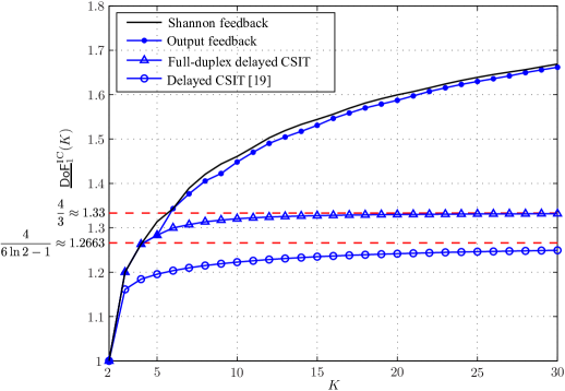
Regarding Eqs. 39 and 38 and the fact that is either or , one can show , which in view of 62 yields . This together with 59, and the fact that , implies that
| (78) |
We now show that . To do so, it suffices to show that . Then, an application of the Squeeze theorem regarding 78 and the fact that will yield the desired result. Using 40, we have
| (79) |
where (a) follows from Eqs. 62 and 39, and (b) uses the fact that the denominator is strictly increasing in for , and thus, is minimized at .
Figure 14 plots our achievable DoFs for the SISO X channel with delayed CSIT and full-duplex transmitter cooperation, given by 36, for , and , and , and compares them with the achievable DoF reported in [19] for the X channel with delayed CSIT. For all values of , our achievable DoF for the full-duplex X channel with delayed CSIT is strictly increasing in and greater than that of the X channel with delayed CSIT. Also, it can be shown using 36 that for a fixed :
| (80) |
For instance, and , as indicated in Fig. 14. Moreover, it follows from 36 and that, if for sufficiently large , then
| (81) |
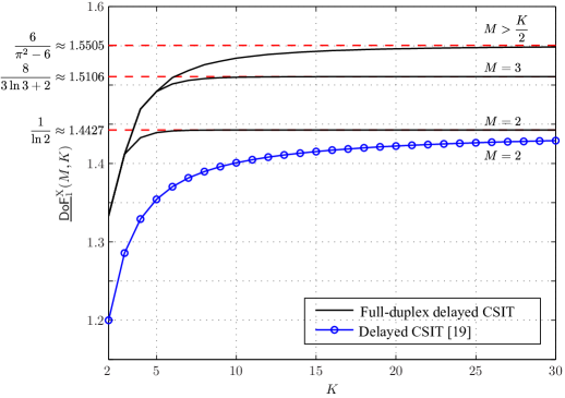
Figure 15 compares our achievable DoF for the X channel with Shannon feedback (given by 42), output feedback (which is by Theorem 4), full-duplex delayed CSIT (given by 36), and delayed CSIT [19] for . It is observed that for ,
| (82) |
Also, one can easily verify using 42 and that
| (83) |
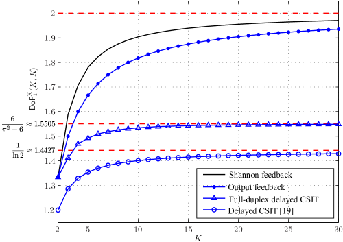
X Conclusions
The SISO AWGN interference and X channels with arbitrary number of users were investigated in this paper, where it was assumed that the CSI is not instantaneously available at the transmitters. Achievable results were obtained on the DoF of these channels under three different assumptions, namely, full-duplex delayed CSIT (where the transmitters access the delayed CSI and can operate in full-duplex mode), output feedback (where each transmitter causally accesses the output of its paired receiver), and Shannon feedback (where each transmitter accesses both the output feedback and delayed CSI). Under each assumption, the transmitters, obtaining side information about each other’s messages through full-duplex or feedback links, could cooperate to align the interference at the receivers in a multi-phase fashion.
For each channel, the transmitters enjoyed a different level of cooperation under each assumption, and hence, different values of DoF were achieved. The achieved DoFs are greater than the best previously reported achievable DoFs for both channels with delayed CSIT, and are strictly increasing with the number of receivers, though approaching limiting values not greater than for asymptotically large networks. Our DoF results under the full-duplex delayed CSIT assumption are the first to demonstrate the potential of full-duplex transmitter cooperation to yield DoF gains in multi-user networks. The problem of DoF characterization of both channels under each of the considered assumptions remains open in the lack of tight upper bounds.
Appendix A Closed Form Expression for the Recursive Eqs. 48 and 60
Consider the following recursive equation:
| (84) |
with and the initial condition . We treat two different cases separately:
(i) : In this case, we have , and hence,
| (85) |
Then, defining , one can write , which implies that , or equivalently,
| (86) |
(ii) : In this case, we have
| (87) |
which can be rewritten as
| (88) |
It immediately follows that
| (89) |
where (a) uses 86 with , and the fact that .
Appendix B Closed Form Expression for the Recursive Eq. (57)
Consider the recursive equation
| (91) |
with and initial condition . The following distinct cases can be differentiated:
(i) : In this case, , and hence,
| (92) |
Now, if , then similar to Appendix A, one can show that
| (93) |
Otherwise, the recursive Eq. (92) can be rewritten as
| (94) |
where (a) uses 93 with , and the fact that .
Equations 93 and 94 yield
| (95) |
Appendix C Closed Form Expression for the Recursive Eq. (70)
References
- [1] M. J. Abdoli, A. Ghasemi, and A. K. Khandani, “Full-duplex transmitter cooperation, feedback, and the degrees of freedom of SISO Gaussian interference and X channels,” in Information Theory, 2012. ISIT 2012. IEEE International Symposium on, 2012.
- [2] C. Shannon, “The zero error capacity of a noisy channel,” Information Theory, IRE Transactions on, vol. 2, no. 3, pp. 8–19, 1956.
- [3] L. Ozarow, “The capacity of the white Gaussian multiple access channel with feedback,” Information Theory, IEEE Transactions on, vol. 30, no. 4, pp. 623–629, 1984.
- [4] ——, “An achievable region and outer bound for the Gaussian broadcast channel with feedback (corresp.),” Information Theory, IEEE Transactions on, vol. 30, no. 4, pp. 667–671, 1984.
- [5] C. Suh and D. Tse, “Feedback capacity of the Gaussian interference channel to within 2 bits,” Arxiv preprint arXiv:1005.3338, 2010.
- [6] S. R. Bhaskaran, “Gaussian broadcast channel with feedback,” Information Theory, IEEE Transactions on, vol. 54, no. 11, pp. 5252–5257, 2008.
- [7] D. Tse and R. Yates, “Fading broadcast channels with state information at the receivers,” Arxiv preprint arXiv:0904.3165, 2009.
- [8] Y. Zhu and D. Guo, “Ergodic fading Z-interference channels without state information at transmitters,” Information Theory, IEEE Transactions on, vol. 57, no. 5, pp. 2627–2647, 2011.
- [9] C. S. Vaze and M. K. Varanasi, “The degrees of freedom regions of MIMO broadcast, interference, and cognitive radio channels with no CSIT,” Arxiv preprint arXiv:0909.5424, 2009.
- [10] V. R. Cadambe and S. A. Jafar, “Interference alignment and degrees of freedom of the -user interference channel,” Information Theory, IEEE Transactions on, vol. 54, no. 8, pp. 3425–3441, 2008.
- [11] ——, “Interference alignment and the degrees of freedom of wireless X networks,” Information Theory, IEEE Transactions on, vol. 55, no. 9, pp. 3893–3908, 2009.
- [12] M. A. Maddah-Ali and D. Tse, “Completely stale transmitter channel state information is still very useful,” Arxiv preprint arXiv:1010.1499v2, 2010.
- [13] C. S. Vaze and M. K. Varanasi, “The degrees of freedom region of the two-user MIMO broadcast channel with delayed CSIT,” in Information Theory, 2011. ISIT 2011. IEEE International Symposium on, 2011, pp. 331–335.
- [14] M. J. Abdoli, A. Ghasemi, and A. K. Khandani, “On the degrees of freedom of three-user MIMO broadcast channel with delayed CSIT,” in Information Theory, 2011. ISIT 2011. IEEE International Symposium on, 2011, pp. 341–345.
- [15] H. Maleki, S. A. Jafar, and S. Shamai, “Retrospective interference alignment,” in Information Theory, 2011. ISIT 2011. IEEE International Symposium on, 2011, pp. 2887–2891.
- [16] A. Ghasemi, A. S. Motahari, and A. K. Khandani, “On the degrees of freedom of X channel with delayed CSIT,” in Information Theory, 2011. ISIT 2011. IEEE International Symposium on, 2011, pp. 909–912.
- [17] A. Ghasemi, M. J. Abdoli, and A. K. Khandani, “On the degrees of freedom of MIMO X channel with delayed CSIT,” in Information Theory, 2012. ISIT 2012. IEEE International Symposium on, 2012.
- [18] M. J. Abdoli, A. Ghasemi, and A. K. Khandani, “On the degrees of freedom of SISO interference and X channels with delayed CSIT,” in Communication, Control, and Computing (Allerton), 2011 49th Annual Allerton Conference on, 2011, pp. 625–632.
- [19] ——, “On the degrees of freedom of -user SISO interference and X channels with delayed CSIT,” Arxiv preprint arXiv:1109.4314, 2011.
- [20] C. S. Vaze and M. K. Varanasi, “The degrees of freedom region and interference alignment for the MIMO interference channel with delayed CSI,” Arxiv preprint arXiv:1101.5809, 2011.
- [21] A. Ghasemi, A. S. Motahari, and A. K. Khandani, “Interference alignment for the MIMO interference channel with delayed local CSIT,” Arxiv preprint arXiv:1102.5673, 2011.
- [22] C. S. Vaze and M. K. Varanasi, “The degrees of freedom region of the MIMO interference channel with Shannon feedback,” Arxiv preprint arXiv:1109.5779, 2011.
- [23] R. Tandon, S. Mohajer, H. V. Poor, and S. Shamai, “On interference networks with feedback and delayed CSI,” Arxiv preprint arXiv:1109.5373, 2011.
- [24] A. Host-Madsen, “Capacity bounds for cooperative diversity,” Information Theory, IEEE Transactions on, vol. 52, no. 4, pp. 1522–1544, 2006.
- [25] V. M. Prabhakaran and P. Viswanath, “Interference channels with source cooperation,” Information Theory, IEEE Transactions on, vol. 57, no. 1, pp. 156–186, 2011.
- [26] S. Yang and D. Tuninetti, “Interference channel with generalized feedback (a.k.a. with source cooperation): Part I: Achievable region,” Information Theory, IEEE Transactions on, vol. 57, no. 5, pp. 2686–2710, 2011.
- [27] R. Tandon and S. Ulukus, “Dependence balance based outer bounds for Gaussian networks with cooperation and feedback,” Information Theory, IEEE Transactions on, vol. 57, no. 7, pp. 4063–4086, 2011.
- [28] Y. Cao and B. Chen, “An achievable rate region for interference channels with conferencing,” in Information Theory, 2007. ISIT 2007. IEEE International Symposium on, 2007, pp. 1251–1255.
- [29] A. Host-Madsen and A. Nosratinia, “The multiplexing gain of wireless networks,” in Information Theory, 2005. ISIT 2005. IEEE International Symposium on, 2005, pp. 2065–2069.
- [30] V. R. Cadambe and S. A. Jafar, “Degrees of freedom of wireless networks with relays, feedback, cooperation, and full duplex operation,” Information Theory, IEEE Transactions on, vol. 55, no. 5, pp. 2334–2344, 2009.
- [31] R. Tandon, S. Mohajer, H. V. Poor, and S. Shamai, “On X-channels with feedback and delayed CSI,” Arxiv preprint arXiv:1201.6313, 2012.