Hole spin relaxation in [001] strained asymmetric Si/SiGe and Ge/SiGe quantum wells
Abstract
Hole spin relaxation in [001] strained asymmetric Si/Si0.7Ge0.3 (Ge/Si0.3Ge0.7) quantum wells is investigated in the situation with only the lowest hole subband being relevant. The effective Hamiltonian of the lowest hole subband is obtained by the subband Löwdin perturbation method in the framework of the six-band Luttinger model, with sufficient basis functions included. The lowest hole subband in Si/SiGe quantum wells is light-hole like with the Rashba spin-orbit coupling term depending on momentum both linearly and cubically, while that in Ge/SiGe quantum wells is a heavy hole state with the Rashba spin-orbit coupling term depending on momentum only cubically. The hole spin relaxation is investigated by means of the fully microscopic kinetic spin Bloch equation approach, with all the relevant scatterings considered. It is found that the hole-phonon scattering is very weak, which makes the hole-hole Coulomb scattering become very important. The hole system in Si/SiGe quantum wells is generally in the strong scattering limit, while that in Ge/SiGe quantum wells can be in either the strong or the weak scattering limit. The Coulomb scattering leads to a peak in both the temperature and hole density dependences of spin relaxation time in Si/SiGe quantum wells, located around the crossover between the degenerate and nondegenerate regimes. Nevertheless, the Coulomb scattering leads to not only a peak but also a valley in the temperature dependence of spin relaxation time in Ge/SiGe quantum wells. The valley is actually due to the crossover from the weak to strong scattering limit. The hole-impurity scattering influences the spin relaxation effectively. In the strong (weak) scattering limit, the spin relaxation time increases (decreases) with increasing impurity density. The spin relaxation time is found to be on the order of 1100 ps (0.110 ps) in Si/SiGe (Ge/SiGe) quantum wells, for the temperatures, carrier/impurity densities and gate voltages of our consideration.
pacs:
72.25.Rb, 71.10.-w, 71.70.EjI Introduction
In recent years, great efforts have been devoted to the design/realization of spintronic devices, which employ the spin degree of freedom in traditional electronics for the sake of higher power efficiency, higher speed, and also greater functionality.aws ; zutic ; dy Among different kinds of hosts for such devices, Si appears to be a particularly promising one and attracts much attention, partly due to the high possibility of eliminating hyperfine couplings by isotopic purification and the well developed microfabrication technology.schaffler In fact, the electron spin relaxation, which is necessary to be understood for the device design, has been widely investigated in Si materials during the last decade. The study on relaxation of electron spin qubit in Si quantum dot suggests that the relaxation rate can be strongly decreased by adding strain.tahan0 The electron spin relaxation in asymmetric -type Si/SiGe quantum wells (QWs) has been investigated both theoreticallytahan and experimentally.wil ; jantsch It is shown that the electron spin relaxation time can be quite long (on the order of s)tahan ; wil ; jantsch due to the weak Rashba spin-orbit couplingrashba (typically about three orders of magnitude smaller than that in QW structures based on III-V semiconductorswil ). The electron spin transport/diffusion in bulk Si with a magnetic field perpendicular to both the directions of spin polarization and spin transport/diffusion has also been studied recently.appelbaum It is revealed that even in the absence of the traditional D’yakonov-Perel’ (DP) relaxation mechanism,dp there is an obvious spin relaxation along spin transport/diffusion, as predicted several years ago from a general QW model without any DP relaxation mechanism but with a magnetic field in the Voigt configuration.weng2002 That is also the case in the symmetric Si/SiGe QWs.zhang
Although a broad interest has been taken in the electron spin relaxation in Si, to our knowledge, the hole spin relaxation has been rarely investigated so far. Glavin and Kim have calculated the spin relaxation of two-dimensional holes in strained asymmetric Si/SiGe (Ge/SiGe) QWs four years ago,glavin and obtained a spin relaxation time of several tens of picoseconds (several sub-picoseconds) in Si/SiGe (Ge/SiGe) QWs with large gate voltage (which induces an electric field at kV/cm) at room temperature. However, the results were obtained by means of the single-particle approximation,sp therefore the effect of the carrier-carrier Coulomb scattering on spin relaxation, which has been revealed to be important in spin relaxation,wu-rev ; glazov ; zhou ; ruan ; leyland ; brand ; glazov1 was not included. Besides, the nondegenerate perturbation method with only the lowest unperturbed subband of each hole state considered as basis function is utilized to calculate the subband energy spectrum and envelope functions in Ref. glavin, . However, as shown later in this paper, only considering the lowest unperturbed subband is inadequate in converging the calculation, but when more unperturbed subbands are included as basis functions, the nondegenerate perturbation method fails. This work is to perform a detailed investigation on hole spin relaxation in asymmetric Si/SiGe and Ge/SiGe QWs by means of the fully microscopic kinetic spin Bloch equation (KSBE) approach,wu-rev with all the relevant scatterings included. Meanwhile, we apply the exact diagonalization method to obtain the energy spectrum and envelope functions, with sufficient unperturbed subbands included. In the KSBE approach, the momentum-dependent spin precessions give rise to the inhomogeneous broadening, with which any scattering (including the Coulomb scattering) leads to an irreversible spin relaxation.wu-rev This approach has been successfully applied to study spin dynamics in quantum wire,cheng ; lv QWyzhou ; zhang ; weng ; zhou ; weng2002 ; lv1 and bulkjiang semiconductor structures. The current work reveals that the Coulomb scattering plays a much more important role in hole spin relaxation in Si/SiGe (Ge/SiGe) QWs. It leads to a peak in both the temperature and density dependences of spin relaxation time in Si/SiGe QWs, where holes are generally in the strong scattering limit. Nonetheless, it leads to not only a peak but also a valley in the temperature dependence of spin relaxation time in Ge/SiGe QWs, where with the change of temperature the holes in Ge/SiGe QWs can be in the either strong or weak scattering limit. Besides, the spin relaxation time can be effectively influenced by the hole-impurity scattering, which tends to weaken the effect of the Coulomb scattering mentioned above with the increase of impurity density.
This paper is organized as follows. In Sec. II the effective Hamiltonian of the lowest hole subband (we focus on the situations with only the lowest subband being relevant) in asymmetric Si/SiGe (Ge/SiGe) QWs is derived. In Sec. III the KSBEs are constructed and the hole spin relaxation in Si/SiGe (Ge/SiGe) QWs is investigated. Finally, we conclude in Sec. IV.
II Effective Hamiltonian
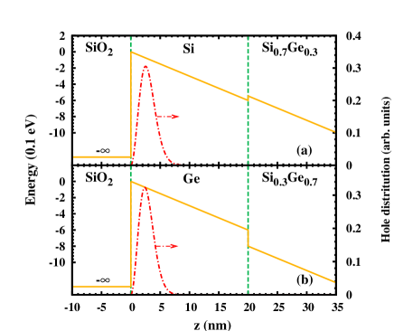
We start our investigation from the -type SiO2/Si/Si0.7Ge0.3 (SiO2/Ge/Si0.3Ge0.7) QWs. The SiO2/Si/Si0.7Ge0.3 and SiO2/Ge/Si0.3Ge0.7 QW structures are illustrated in Fig. 1. The Si (Ge) layer is [001] grown with a wide width ( nm). The SiO2 layer is assumed to be an infinite potential barrier. With the valence band discontinuity at the Si/Si0.7Ge0.3 (Ge/Si0.3Ge0.7) interface [ meV ( meV)]schaffler ignored due to the large gate voltage (inducing an electric field kV/cm) and wide well width,glavin the triangular potential approximation is adoptedglavin ; fischetti ; low and the well width then becomes irrelevant.
Based on the theory of Luttinger-Kohnluttinger1 ; luttinger2 and Bir-Pikus,bir the valence-band structure of the strained QWs can be described by the 66 effective-mass Hamiltonian,glavin ; note1
| (1) |
Here is the Luttinger Hamiltonianluttinger1 ; luttinger2 ; bir with corresponding to the part with . is the contribution due to the biaxial strain.luttinger1 ; luttinger2 ; bir ; chao is the confining potential and is the 66 unit matrix. The -components of the subband envelope functions (the - and -components are plane waves) obtained by solving the eigen-equation of are labeled as
| (14) | |||
| (27) | |||
| (40) |
Here , and represent the light hole (LH), heavy hole (HH), and split-off (SO) hole states, respectively, and is the subband number. The solution of the envelope functions is stated in Appendix A.
| Material | (g/cm3) | (eV) | (108 eV/cm) | (eV) | (105 cm/s) |
| Si | 2.33 | 5.03 | 8.7 | 0.063 | 9.0 |
| Ge | 5.32 | 3.5 | 7.0 | 0.037 | 5.4 |
| Si | 4.285 | 0.339 | 1.446 | ||
| Ge | 13.38 | 4.24 | 5.69 |
The Löwdin partitioningwinkler is performed upto second order in on the basis constructed by (=1, 2; =, , ) to obtain the effective Hamiltonian of the lowest hole subband.note2 Due to the biaxial strain,luttinger1 ; luttinger2 ; bir ; chao the lowest subband in Si/SiGe QWs is a LH-like state (LH0), which is an admixture of LH and SO hole states, while that in Ge/SiGe QWs is a pure HH state (HH0). The effective Hamiltonian of the lowest hole subband in Si/SiGe (Ge/SiGe) QWs can be written asglavin
| (41) |
where is the in-plane momentum, [] is the in-plane effective mass of the lowest light (heavy) hole subband in Si/SiGe (Ge/SiGe) QWs, are the Pauli matrices, and [] is the Rashba term of the LH0 (HH0) subband in Si/SiGe (Ge/SiGe) QWs. has both the linear and cubic dependences on momentum, whereas has only the cubic dependence. For the LH0 subband in Si/SiGe QWs,
| (42) | |||||
| (43) | |||||
| (44) | |||||
| (45) | |||||
| (46) | |||||
with
| (47) | |||||
| (48) | |||||
| (49) | |||||
For the HH0 subband in Ge/SiGe QWs,
| (50) | |||||
| (51) | |||||
| (52) | |||||
| (53) | |||||
with
| (54) | |||||
Here , and are the valence band parameters, which relate to the Luttinger parameters (Table 1) , and through , and . (=, , ) are the subband energy levels. and are defined as and . It is noted that in Ref. glavin, the coefficients , and miss the pre-factor and meanwhile misses the summation over (i.e., the contribution due to the higher LH subbands, which is in fact negligibly small). Unlike the work by Glavin and Kimglavin where the nondegenerate perturbation method with only the lowest unperturbed subband of each hole state being accounted [refer to Eqs. (3–9) in Ref. glavin, ] is employed in obtaining the subband energy spectrum and the envelope functions , we apply the exact diagonalization method with sufficient unperturbed subbands [2 (20) for each hole state in Si/SiGe (Ge/ SiGe) QWs] for the sake of convergence. In fact, the calculation with only the lowest unperturbed subband of each hole state is inadequate for the convergence. Moreover, the calculation with more unperturbed subbands included may cause divergence as long as the nondegenerate perturbation method is utilized. When performing the subband Löwdin partition methodwinkler to obtain the effective Hamiltonian of the lowest subband, we choose sufficient envelope functions as basis functions. For Si/SiGe (Ge/SiGe) QWs, the number of envelope functions containing and is 4 (40) in total, and the number of envelope functions is 2 (20). The reason that more basis functions are needed for Ge/SiGe QWs comes from the fact that the couplings between the hole subbands are stronger than those in the Si/SiGe QWs (the Luttinger parameters in Ge are much larger than those in Si but under the strain the energy differences between hole subbands are comparable in Si/SiGe and Ge/SiGe QWs).
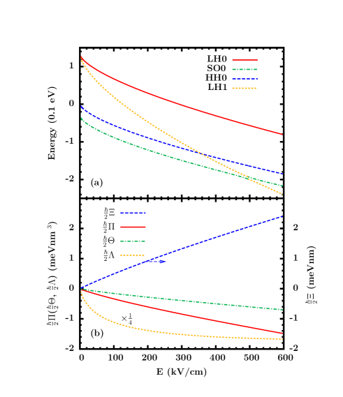
According to Eqs. (42) and (50), the in-plane effective mass of LH0 subband in Si/SiGe QWs is calculated to be about in the whole electric field range under consideration, and that of the HH0 subband in Ge/SiGe QWs is . We plot the energy levels of four subbands in Si/SiGe QWs (the first and second LH subbands LH0 and LH1, the first HH subband HH0, and the first SO subband SO0) at point in Fig. 2(a) and the spin-orbit coupling coefficients of the LH0 subband in Si/SiGe QWs (, and ) and the HH0 subband in Ge/SiGe QWs () in Fig. 2(b). As shown in Fig. 2(a), a crossing between the LH1 and HH0 subbands appears at about kV/cm and an anticrossing between the LH1 and SO0 subbands appears around kV/cm, respectively. It is noted that notwithstanding the fact that our calculation goes to the infinitesimal electric field regime in Fig. 2, only the results in the large electric field regime (i.e., kV/cm for QWs with well width nm) are valid (the spin relaxation investigated later is also in the large electric field regime), as our model fails in the small electric field regime due to the disregard of the discontinuity in the Si/SiGe (Ge/SiGe) interface. In this work the temperature dependence of band parameterszutic ; Eld is not taken into account, due to both the weak temperature dependence of band parameters and the negligible contribution from the conduction band.note1
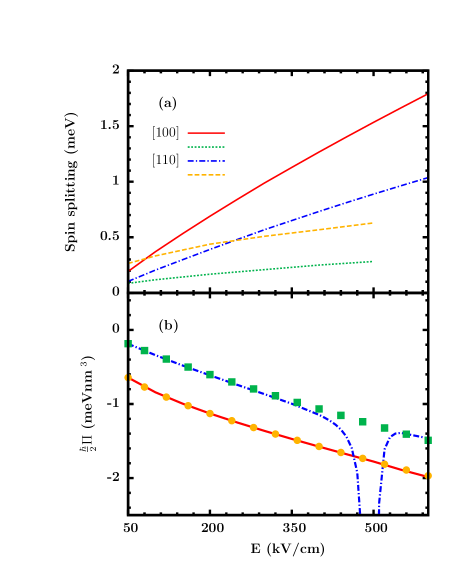
We also calculate the spin splitting for holes in Si/SiGe QWs with in-plane kinetic energy being ( K) along the [100] (solid curve) and [110] (chain curve) direction in Fig. 3(a), as done in Ref. glavin, . The dotted and dashed curves are taken from Ref. glavin, , corresponding to the spin splittings along the [100] and [110] directions, respectively. It is shown that our results differ from those in Ref. glavin, .comment
We examine our results by further carrying out a calculation of spin-orbit coupling coefficients/spin splitting with the envelope functions obtained by the nondegenerate perturbation method as that in Ref. glavin, (also refer to Appendix A of this paper), but with the spin-orbit coupling coefficients obtained in this work [i.e., Eqs. (47-49) and (54)]. As a comparison, we plot the electric field dependence of [Eq. (48)] in Fig. 3(b), where the solid (chain) curve and the dots (squares) are results from the perturbation and exact diagonalization methods, respectively with the lowest one (two) unperturbed subband (subbands) of each hole state considered. We find that when only the lowest unperturbed subband of each hole state is considered, the perturbation calculation and our exact diagonalization calculation yield almost the identical results [compare the solid curve and the dots in Fig. 3(b)]. We also find that, as said above, when more unperturbed subbands of each hole state are accounted, the nondegenerate perturbation method may cause divergence in the spin-orbit coupling coefficients/spin splitting (a divergence near kV/cm in the chain curve is observed). The divergence is caused by the degeneracy of the LH subband and the SO subband (refer to Appendix A for details), and disappears in the exact diagonalization calculation (see squares in the figure). Besides, the large discrepancy between the results with different number of unperturbed subbands included indicates that only considering the lowest subband of each hole state is inadequate for the convergence of calculation. As a result, the exact diagonalization calculation with sufficient unperturbed subbands of each hole state included is necessary.
III Hole spin relaxation
We perform the fully microscopic KSBE approachwu-rev to study the hole spin relaxation. The KSBEs constructed by the nonequilibrium Green function method readwu-rev
| (55) |
in which represent the density matrices of holes. are the coherent terms describing the coherent spin precessions due to the effective magnetic fields from the Rashba term and the Hartree-Fock Coulomb interaction. stand for the scattering terms, including the hole-deformation optical/acoustic phonon,bufler hole-impurity and hole-hole Coulomb scatterings. Expressions of the coherent and scattering terms are given in detail in Ref. weng, . What need to be specified are the matrix elements of the hole-phonon interaction in the scattering terms. The matrix elements of hole-deformation acoustic phonon scattering and hole-deformation optical phonon scattering are and , respectively. Here is the phonon momentum. The values of mass density , deformation potentials and , the optical phonon energy and the sound velocity in Si and Ge are listed in Table 1. is the form factor with for Si/SiGe QWs and for Ge/SiGe QWs. By numerically solving the KSBEs, one can obtain the time evolution of density matrices and then the spin relaxation time. In the calculation, the initial spin polarization of holes is set to be 5 %.
III.1 Hole spin relaxation in Si/SiGe QWs
We first study the spin relaxation of the lowest hole subband in Si/Si0.7Ge0.3 QWs. kV/cm unless otherwise specified. The LH0 holes have a distribution along the -direction as shown in Fig. 1(a) by the chain curve. The spin-orbit coupling coefficients are meV nm, meV nm3 and meV nm3, respectively [Fig. 2(b)]. Moreover, due to the quite small material parameter (or ) in Si, the linear part of the Rashba term in Si/SiGe QWs is relatively more important. The main results are plotted in Figs. 4–7, showing the spin relaxation with different temperatures, carrier/impurity densities and scatterings.
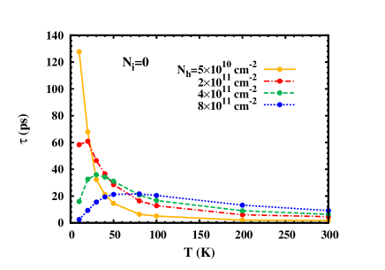
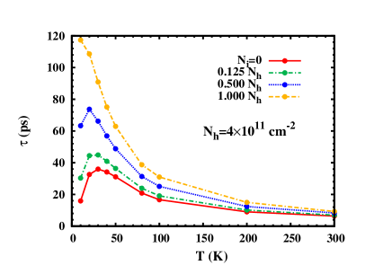
Figure 4 shows the temperature dependence of spin relaxation time with different hole densities. The impurity density is set to be zero. A peak, appearing at a temperature around the Fermi temperature ( is the hole Fermi energy. K with density cm-2), is observed except when the hole density is too low. This kind of peak has been predicted by Zhou et al. in high-mobility -doped GaAs QWs zhou and later observed by Ruan et al. experimentally at about in the temperature dependence of electron spin relaxation.ruan Similar peaks have also been predicted very recently in the temperature dependence of electron spin relaxation at a temperature in the range of (, ) in intrinsic bulk GaAsjiang and at a temperature around the hole Fermi temperature in impurity-free -type GaAs QWs where the hole density is much higher than the electron density.yzhou In fact, this feature appears in the electron spin relaxation of strong scattering system with the DP relaxation mechanism being dominant when the Coulomb scattering (either the intraband electron-electron or the interband electron-hole Coulomb scattering) is the main scattering. When the intraband electron-electron Coulomb scattering dominates,zhou ; ruan ; jiang the peak appears around the crossover from the degenerate to nondegenerate regime of electrons. When the interband Coulomb scattering dominates, the peak appears around the crossover from the degenerate to nondegenerate regime of holes in -type systems.yzhou
It is known that in the strong scattering system, strengthening scattering can suppress the inhomogeneous broadening and tends to prolong the spin relaxation time within the DP relaxation mechanism,wu-rev ; zhou ; jiang ; weng ; yzhou ; lv1 and that the Coulomb scattering rate has a dependence in the degenerate regime but a () dependence in the nondegenerate regime in the two (three)-dimensional carrier systems.glazov ; giu Thus with the increase of , the dominant Coulomb scattering tends to cause first an increase and then a decrease in the electron spin relaxation time. Meanwhile, the increase of inhomogeneous broadening with tends to cause a monotonous decrease in the spin relaxation time and thus a shift of the peak in the - curve towards the lower temperature. The magnitude of the latter effect depends on the form of the momentum dependence of the DP term. When the DP term mainly depends on the momentum linearly (cubically), the latter effect is moderate (strong). The above scenario also holds in the hole spin relaxation, such as the case considered here. The hole system in Si/SiGe QWs is in the strong scattering limit where the Coulomb scattering dominates (as discussed later) and the linear part of the Rashba term is more important, thus the peak in the - curve is obvious near . However, when the hole density is low enough and thus holes are in the nondegenerate regime throughout the temperature regime under consideration, the spin relaxation time decreases monotonously with temperature, as shown by the solid curve in Fig. 4.
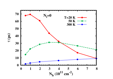
A similar phenomenon is expected to happen in the density dependence of spin relaxation time, as the Coulomb scattering rate has an () dependence in the degenerate regime while an dependence in the nondegenerate regime in two (three)-dimensional systems.glazov ; giu This is exactly the case,jiang ; yzhou as shown by Fig. 5. Nevertheless, when the temperate is high enough and thus holes are in the nondegenerate regime throughout the density range under consideration, the spin relaxation time increases monotonously with density, as shown by the dotted curve in Fig. 5.
In Fig. 6 the spin relaxation time against temperature with different impurity densities is plotted. It shows that adding impurities reduces spin relaxation rate. That is because the inhomogeneous broadening is suppressed by introducing hole-impurity scattering in the strong scattering limit.wu-rev ; zhou ; jiang ; weng ; lv1 With the increase of impurity density , the hole-impurity scattering, which is insensitive to in low temperature regime, becomes important. Thus the peak in - curve due to the Coulomb scattering becomes less pronounced or even disappears.zhou ; jiang That is the reason why the peak is easier to be observed experimentally in high-mobility samples.zhou ; ruan It is also noted that the impurity scattering has marginal effect on spin relaxation near room temperature, which is understood by recalling that the impurity scattering rate decreases with carrier energy.tomizawa
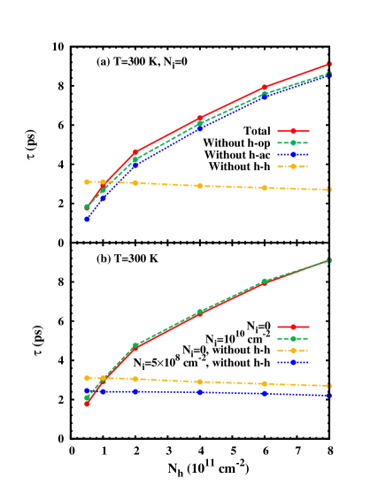
To understand the relative importance of different scatterings in spin relaxation, we calculate the spin relaxation time with different scatterings included and show its density dependence in Fig. 7. is taken to be 300 K. In Fig. 7(a) the impurity density . The solid curve corresponds to the case with all the scatterings (the hole-hole Coulomb, hole-optical phonon and hole-acoustic phonon scatterings) included. The dashed, dotted and chain curves correspond to the cases without the hole-optical phonon, hole-acoustic phonon and hole-hole Coulomb scattering, respectively. By comparing these four curves, one finds that: (i) Even with K, the hole-hole Coulomb scattering plays a much more important role than the hole-phonon scattering (in addition, similar calculations show that when K, the hole-phonon scattering can be completely ignored); (ii) The acoustic phonon scattering plays a relatively more efficient role than the optical phonon scattering [that is because the optical phonon energy is high (63 meV) while the hole Fermi energy is low due to the large in-plane effective mass (0.27)]. In fact, the hole system under consideration is in the strong scattering limit generally, but falls into the weak scattering limit when the hole-hole Coulomb scattering is removed artificially. (When K here, the momentum relaxation time due to the relatively stronger hole-acoustic phonon scattering is about 2.1 ps, while the mean spin precession ratewu-rev ; zhou ; lv1 is about 0.520.56 ps-1 with the change of hole density. Thus without the hole-hole Coulomb scattering, , indicating the weak scattering limit.) This feature can be justified by comparing two groups of curves in Fig. 7(b). One group with the hole-hole Coulomb scattering (the solid and dashed curves) indicates that adding a small amount of impurities helps increasing , corresponding to the strong scattering case, while the other group without the hole-hole Coulomb scattering (the chain and dotted curves) shows an inverse effect (i.e., a decrease in ) with adding quite a small amount of impurities, which typically happens in the weak scattering limit.wu-rev ; lv1
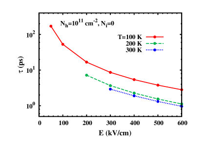
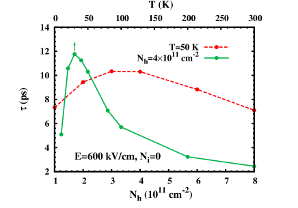
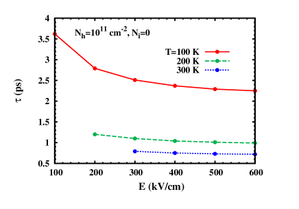
Finally, we investigate the electric field dependence of spin relaxation. The hole spin relaxation time against electric field with different temperatures is plotted in Fig. 8. For each temperature, we choose the appropriate range of electric field to ensure that the effect of second hole subband is irrelevant. It is shown that with the increase of electric field, the spin relaxation time is shortened due to the strengthened spin-orbit coupling. Besides, as a comparison to the features of spin relaxation with kV/cm, we also present the hole density and temperature dependences of spin relaxation with kV/cm in Fig. 9. One finds that the peak in hole density/temperature dependence of the hole spin relaxation time (the dashed/solid curve in Fig. 9) due to the Coulomb scattering still exists. Moreover, the location of the peak remains almost the same despite the change of the gate voltage. This indicates that when the linear part of the Rashba term is important, the trend of variation of the hole spin relaxation time mainly associates with that of the Coulomb scattering strength around the crossover between the degenerate and nondegenerate regimes, whereas the increase of the inhomogeneous broadening with increasing temperature/hole density is moderate (even with the increase of the spin-orbit coupling coefficients by the larger gate voltage).
III.2 Spin relaxation in Ge/SiGe QWs
The hole spin relaxation in Ge/Si0.3Ge0.7 QWs is also investigated. The HH0 holes have a distribution along the -direction as shown in Fig. 1(b) by the chain curve when the electric field is kV/cm. In Fig. 10 the spin relaxation time against temperature with electric field kV/cm [at which meV nm3, as shown in Fig. 2(b)] is plotted. It is shown that the hole spin relaxation time in Ge/SiGe QWs is much shorter than that in Si/SiGe QWs. That is because the inhomogeneous broadening in Ge/SiGe QWs is quite strong, as the spin-orbit interaction in Ge/SiGe QWs is relatively stronger (in consistence with the heavier Ge element) and the Rashba term depends on momentum cubically. Apart from the fast spin relaxation, a new phenomenon emerges – when the hole density is relatively high, not only a peak in - curve is present, but also a valley before the peak is observed.
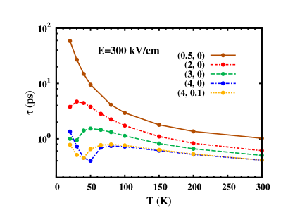
Unlike the case in Si/SiGe QWs where the peak is close to the Fermi temperature (Fig. 4), the peak here is located at a temperature about (e.g., K with density cm-2). As discussed previously about the spin relaxation in Si/SiGe QWs, the Coulomb scattering strength first increases and then decreases with increasing temperature (accompanying the crossover from the degenerate to nondegenerate regime), tending to cause a peak in the - curve around the Fermi temperature in the strong scattering limit. However, the enhancement of inhomogeneous broadening with is strong here as the Rashba term depends on momentum cubically (unlike the case in Si/SiGe QWs where the linear part of the Rashba term is important). Thus with both effects accounted, the shift of the peak towards a lower temperature is expected. By comparing the spin relaxation in high temperature regime of the three curves with in Fig. 10, one finds that the spin relaxation time decreases with hole density monotonically, which is different from the case in Si/SiGe QWs (indicated by the dotted curve in Fig 5). That is because the Rashba term here depends on the momentum cubically and the inhomogeneous broadening increases with density strongly with an dependence.
While the peak is associated with the crossover from the degenerate to nondegenerate regime, the valley in Fig. 10 is actually related to the crossover from the weak to strong scattering limit. When the temperature is low enough and the density is high, the hole system is highly degenerate (due to the high Fermi energy) and thus the dominant Coulomb scattering becomes very weak. The hole system then falls into the weak scattering limit. Therefore with the increase of temperature from the very low temperature, the strengthening of scattering reduces the spin relaxation time first, until the crossover to the strong scattering system, and then increases the spin relaxation time – this leads to a valley in the - curve in the degenerate regime. The dotted curve in Fig. 10 stands for the case with the same hole density as the chain curve but with a small amount of impurities. It is observed again that introducing a weak impurity scattering in the weak (strong) scattering limit leads to a decrease (an increase) of the spin relaxation time.wu-rev ; lv1
The electric field dependence of spin relaxation is also investigated, with the hole spin relaxation time against electric field under different temperatures plotted in Fig. 11. It is shown that the spin relaxation time decreases with electric field slowly in the large electric field regime, corresponding to the marginal electric field dependence of the spin-orbit coupling strength in the large electric field regime [refer to the dotted curve in Fig. 2(b)].
IV Conclusion
In conclusion, we have investigated the hole spin relaxation in [001] strained asymmetric Si/Si0.7Ge0.3 (Ge/Si0.3Ge0.7) QWs with large gate voltage in this work. We focus on the situations with only the lowest hole subband being relevant. The effective Hamiltonian of the lowest hole subband is obtained by the subband Löwdin perturbation method in the framework of the six-band Luttinger model, with sufficient basis functions included for the convergence of calculation. Due to the biaxial strain, the lowest subband in Si/SiGe QWs is a light hole-like state, while that in Ge/SiGe QWs is a heavy hole state.
We apply the fully microscopic KSBE approach to investigate the hole spin relaxation in Si/SiGe (Ge/SiGe) QWs. By means of this approach, all the relevant scatterings, such as the hole-phonon, hole-impurity and the hole-hole Coulomb scatterings can be taken into account explicitly. It is discovered that the hole-phonon scattering is very weak compared to the hole-hole Coulomb scattering, even at high temperatures. This makes the hole-hole Coulomb scattering to play a very important role in spin relaxation. It leads to a peak of spin relaxation time in both the temperature and carrier density dependences in Si/SiGe QWs. The peak is associated with the crossover from the degenerate to nondegenerate regime of hole system, and thus locates around the crossover point. However, the increase of inhomogeneous broadening with temperature/hole density tends to lead to a shift of the peak towards a lower temperature/hole density. The magnitude of the shift depends on the form of the momentum dependence of the Rashba term. For Si/SiGe (Ge/SiGe) QWs, the Rashba term mainly (only) depends on momentum linearly (cubically), and thus the shift of the peak is marginal (obvious). In addition, in contrast to the GaAs QWs where the peak in the temperature dependence of the electron spin relaxation can only be observed for high mobility samples with low carrier density,zhou the peak predicted in Si/SiGe (Ge/SiGe) QWs can be observed even at high carrier density, thanks to the weak hole-phonon scattering. The Coulomb scattering also leads to a valley at low temperature in the temperature dependence of hole spin relaxation time in Ge/SiGe QWs with high hole density, which is related to the crossover from the weak to strong scattering limit. The hole spin relaxation time can be effectively influenced by the hole-impurity scattering, tending to weaken the effect of Coulomb scattering mentioned above with the increase of impurity density. Apart from the abundant temperature and hole/impurity density dependences, the spin relaxation time decreases with the gate voltage, accompanying the increase of spin-orbit coupling strength.
The hole spin relaxation time, depending on the temperature, carrier/impurity density and gate voltage, is found to be on the order of 1100 ps (0.110 ps) in Si/SiGe (Ge/SiGe) QWs within the scope of our investigation. These time scales are much shorter than the electron spin relaxation time in Si/SiGe QWs (on the order of s).tahan ; wil ; jantsch A hole spin relaxation time on the order of 0.11 ps was theoretically reported in -doped GaAs QWs (with temperature being 100300 K, hole density being cm-2, impurity density being 01 times hole density and gate voltage induced electric field being about 100 kV/cm)lv1 and a hole spin relaxation time of 4 ps was experimentally observed in -doped GaAs QWs (at 10 K).damen Thus, generally, the hole spin relaxation time in Si/SiGe (Ge/SiGe) QWs is longer than (comparable with) the hole spin relaxation time in GaAs QWs. It should be pointed out at last that the strain in Si/SiGe (Ge/SiGe) QWs plays an important role in spin relaxation, as it shifts the energy levels of the light hole states away from the heavy hole ones. If the strain is removed (e.g., in SiO2/Si or SiO2/Ge inversion layer), the coupling between the light hole and heavy holea states are strengthened and the hole spin relaxation should be enhanced.
Acknowledgements.
This work was supported by the National Natural Science Foundation of China under Grant No. 10725417, the National Basic Research Program of China under Grant No. 2006CB922005 and the Knowledge Innovation Project of Chinese Academy of Sciences. We thank K. W. Kim and B. A. Glavin for valuable discussions.Appendix A Solution of the envelope functions
The envelope functions (=1, 2; =, , ) satisfy the eigen-equation
| (56) |
with . has only one component , satisfying with , which can be solved directly. The envelope functions ( =, ) have two components, with and satisfying
| (61) |
Here
| (67) | |||||
with the second term representing the contribution from the biaxial strain.luttinger1 ; luttinger2 ; bir ; chao , where and are the elastic constants, is the deformation potential constant and is the relative lattice mismatch in the interface.chao ; schaffler is 95.8 meV ( meV) for Si/Si0.7Ge0.3 (Ge/Si0.3Ge0.7) QWs. is the SO splitting. The solutions with correspond to the LH-like states and thus equals to . Otherwise the solutions are deemed as the SO-like states with .
An unitary transformation which diagonalizes the strain term in Eq. (67) is performed on Eq. (61), leading to as
| (71) | |||||
Here
| (74) |
is the unitary matrix, with , and . , and in Eq. (71) are
| (77) |
It is noted that expressions (LABEL:effe1-77) about the effective masses are valid for both the Si/SiGe QWs (with ) and Ge/SiGe QWs (with ), while those in Ref. glavin, [Eqs. (5-6)] equal to Eqs. (LABEL:effe1-77) only when , i.e., they are valid only for Si/SiGe QWs.
can be separated into the diagonal and off-diagonal parts. In the nondegenerate perturbation method, is treated as the perturbation term. The eigen-equation of can be solved directly, with the eigen-values and and the corresponding eigen-functions
| (82) |
determined by the Schrödinger equation (, 2). In this paper, the term “unperturbed subbands” mentioned in the discussion of perturbation (exact diagonalization) method actually means the eigen-states of , i.e., the states with energy levels being and wavefunctions being Eq. (82).
To the first order of , the perturbed eigen-values are and , and the corresponding perturbed eigen-functions are
| (85) |
and
| (88) |
respectively. Here (, , 2). Finally the eigen-values of are and , and the corresponding eigen-functions are
| (91) |
and
| (94) |
It is noted that the nondegenerate perturbation method is valid when only the two subbands with energy and (i.e., the lowest unperturbed subbands corresponding to the LH-like and SO-like hole states respectively) are accounted. Otherwise, when more subbands are included, the divergence may occur in the calculation if two energy levels and are close to each other, as there are terms proportional to in the envelope functions ( and ) [refer to Eqs. (91–94)]. This divergence goes to the spin-orbit coupling coefficients and , and finally the spin splitting.
For the sake of convergence of the envelope functions and thus the spin-orbit coupling coefficients and spin splitting, sufficient subbands have to be considered. Thus, instead of the nondegenerate perturbation method, we apply the exact diagonalization method to obtain the eigen-states of , with sufficient basis functions constructed by the two sets of functions in Eq. (82) [2 (20) of each set for Si/SiGe (Ge/SiGe) QWs].
References
- (1) D. D. Awschalom, D. Loss, and N. Samarth, Semiconductor Spintronics and Quantum Computation (Springer, Berlin, 2002).
- (2) I. Žutić, J. Fabian, and S. D. Sarma, Rev. Mod. Phys. 76, 323 (2004); J. Fabian, A. Matos-Abiague, C. Ertler, P. Stano, and I. Žutić, Acta Phys. Slovaca 57, 565 (2007).
- (3) M. I. D’yakonov, Spin Physics in Semiconductors (Springer, Berlin, 2008).
- (4) F. Schäffler, Semicond. Sci. Technol. 12, 1515 (1997).
- (5) C. Tahan, M. Friesen, and R. Joynt, Phys. Rev. B 66, 035314 (2002).
- (6) C. Tahan and R. Joynt, Phys. Rev. B 71, 075315 (2005).
- (7) W. Jantsch, Z. Wilamowski, N. Sandersfeld, M. Mühlberger, and F. Schäffler, Physica E 13, 504 (2002).
- (8) Z. Wilamowski, W. Jantsch, H. Malissa, and U. Rössler, Phys. Rev. B 66, 195315 (2002).
- (9) Y. A. Bychkov and E. I. Rashba, J. Phys. C 17, 6039 (1984).
- (10) I. Appelbaum, B. Huang, and D. J. Monsma, Nature 447, 295 (2007).
- (11) M. I. D’yakonov and V. I. Perel’, Zh. Éksp. Teor. Fiz. 60, 1954 (1971) [Sov. Phys. JETP 33, 1053 (1971)].
- (12) M. Q. Weng and M. W. Wu, Phys. Rev. B 66, 235109 (2002).
- (13) P. Zhang and M. W. Wu, Phys. Rev. B 79, 075303 (2009).
- (14) B. A. Glavin and K. W. Kim, Phys. Rev. B 71, 035321 (2005).
- (15) F. Meier and B. P. Zakharchenya, Optical Orientation (North-holland, Amsterdam, 1984).
- (16) M. W. Wu and C. Z. Ning, Eur. Phys. J. B 18, 373 (2000); M. W. Wu, J. Phys. Soc. Jpn. 70, 2195 (2001); M. Q. Weng and M. W. Wu, Phys. Rev. B 68, 075312 (2003).
- (17) M. M. Glazov and E. L. Ivchenko, Pis’ma Zh. Éksp. Teor. Fiz. 75, 476 (2002) [JETP Lett. 75, 403 (2002)]; Zh. Éksp. Teor. Fiz. 126, 1465 (2004) [JETP 99, 1279 (2004)].
- (18) J. Zhou, J. L. Cheng, and M. W. Wu, Phys. Rev. B 75, 045305 (2007).
- (19) X. Z. Ruan, H. H. Luo, Y. Ji, Z. Y. Xu, and V. Umansky, Phys. Rev. B 77, 193307 (2008).
- (20) W. J. H. Leyland, G. H. John, R. T. Harley, M. M. Glazov, E. L. Ivchenko, D. A. Ritchie, I. Farrer, A. J. Shields, and M. Henini, Phys. Rev. B 75, 165309 (2007).
- (21) M. A. Brand, A. Malinowski, O. Z. Karimov, P. A. Marsden, R. T. Harley, A. J. Shields, D. Sanvitto, D. A. Ritchie, and M. Y. Simmons, Phys. Rev. Lett. 89, 236601 (2002).
- (22) M. M. Glazov and E. L. Ivchenko, arXiv:0905.4393.
- (23) J. L. Cheng, M. Q. Weng, and M. W. Wu, Solid State Commun. 128, 365 (2003).
- (24) C. Lü, U. Zülicke, and M. W. Wu, Phys. Rev. B 78, 165321 (2008).
- (25) Y. Zhou, J. H. Jiang, and M. W. Wu, arXiv:0905.2790.
- (26) C. Lü, J. L. Cheng, and M. W. Wu, Phys. Rev. B 73, 125314 (2006).
- (27) M. Q. Weng, M. W. Wu, and L. Jiang, Phys. Rev. B 69, 245320 (2004).
- (28) J. H. Jiang and M. W. Wu, Phys. Rev. B 79, 125206 (2009).
- (29) M. V. Fischetti, Z. Ren, P. M. Solomon, M. Yang, and K. Rim, J. Appl. Phys. 94, 1079 (2003).
- (30) T. Low, M. F. Li, Y. C. Yeo, W. J. Fan, S. T. Ng, and D. L. Kwong, J. Appl. Phys. 98, 024504 (2005).
- (31) J. M. Luttinger and W. Kohn, Phys. Rev. 97, 869 (1955).
- (32) J. M. Luttinger, Phys. Rev. 102, 1030 (1956).
- (33) G. L. Bir and G. E. Pikus, Symmetry and Strain-Induced Effects in Semiconductors (Wiley, New York, 1974).
- (34) The direct energy gap at point is much larger than the split-off splitting in Si ( eV and eV),low thus the contribution to the spin-splitting of the lowest light hole subband from the conduction bands can be neglected. in Ge is relatively smaller ( eV and eV),low but the conduction band is found to have no contribution to the spin-splitting of the lowest heavy hole subband. Thus the 66 Luttinger model rather than the larger (extended) Kane modelwinkler is utilized in the study.
- (35) C. Y. -P. Chao and S. L. Chuang, Phys. Rev. B 46, 4110 (1992).
- (36) R. Winkler, Spin-Orbit Coupling Effects in Two-Dimensional Electron and Hole Systems (Springer, Berlin, 2003).
- (37) As the electric-field potential is included in solving the subband energy spectrum and envelope functions, in the basis composed of these subband envelope functions, only the second (instead of thirdwinkler ) order perturbation calculation in Löwdin partitioning is required.
- (38) F. M. Bufler, A. Schenk, and W. Fichtner, J. Appl. Phys. 90, 2626 (2001).
- (39) P. S. Eldridge, W. J. H. Leyland, P. G. Lagoudakis, O. Z. Karimov, M. Henini, D. Taylor, R. T. Phillips, and R. T. Harley, Phys. Rev. B 77, 125344 (2008).
- (40) In fact, even when the expressions of the spin-orbit coupling coefficients in Ref. glavin, are adopted and the nondegenerate perturbation method with only the lowest unperturbed subband of each hole state considered is utilized to obtain envelope functions , the results in Ref. glavin, still can not be repeated.
- (41) G. F. Giulianni and G. Vignale, Quantum Theory of the Electron Liquid (Cambridge University Press, Cambridge, England, 2005).
- (42) K. Tomizawa, Numerical Simulation of Submicron Semiconductor Devices (Artech House, Boston, 1993).
- (43) T. C. Damen, L. Viña, J. E. Cunningham, J. Shah, and L. J. Sham, Phys. Rev. B 67, 3432 (1991).