Creating a low-dimensional quantum gas using dark states in an inelastic evanescent-wave mirror
Abstract
We discuss an experimental scheme to create a low-dimensional gas of ultracold atoms, based on inelastic bouncing on an evanescent-wave mirror. Close to the turning point of the mirror, the atoms are transferred into an optical dipole trap. This scheme can compress the phase-space density and can ultimately yield an optically-driven atom laser. An important issue is the suppression of photon scattering due to “cross-talk” between the mirror potential and the trapping potential. We propose that for alkali atoms the photon scattering rate can be suppressed by several orders of magnitude if the atoms are decoupled from the evanescent-wave light. We discuss how such dark states can be achieved by making use of circularly-polarized evanescent waves.
32.80.Pj, 03.75.-b, 42.50.Vk
I Introduction
The only route to quantum degeneracy in a dilute atomic gas which has been experimentally successful so far, is evaporative cooling [1, 2, 3]. Other routes to quantum degeneracy, in particular all-optical methods, have been elusive until now. Nevertheless it is interesting as well as important to keep exploring alternative methods which do not rely on atomic collisions. Such systems may be held away from thermal equilibrium and may therefore constitute a closer matter-wave analogy to the optical laser, as compared to atom lasers based on Bose-Einstein condensation [4]. In addition, the physics will be quite different because a different physical, viz. optical, interaction would be used to populate the macroscopic quantum state: the amplification of a coherent matter wave, while emitting photons.
Several proposals for an optically-driven atom laser have previously been published. They have in common that a macroscopic quantum state is populated using an optical Raman transition [5, 6]. One problem that has been anticipated from the beginning, is heating and trap loss caused by reabsorption of the emitted photons. Therefore later proposals and current experiments [7, 8] have aimed at a reduced dimensionality, based on optical pumping close to a surface [9, 10, 11, 12]. At the same time, there is also increasing interest in the low-dimensional equivalents of Bose-Einstein condensation in ultracold gases [13]. Here we argue that an evanescent-wave mirror is particularly promising for loading a low-dimensional trap close to a surface.
We extend previous work [5, 6] so that it can be applied to the alkali atoms. Being the favorite atoms for laser-cooling, the application to the alkalis will make this kind of experiments more easily accessible. In comparison to previous experiments with metastable rare gas atoms [8], the alkalis have the advantage that they do not suffer from Penning ionization. Furthermore, several alkali species have been cooled to the Bose-Einstein condensation, which makes them good candidates to create also low-dimensional quantum degeneracy. The extension to the alkalis is nontrivial because the splitting between the hyperfine ground states is not large enough to address them separately with far detuned lasers. The resulting “cross-talk” would lead to large photon scattering rates in the trap, as will be explained below. We propose to use circularly-polarized evanescent waves and to trap alkali atoms in “dark states”. This allows the detuning to be increased and the photon scattering rate to be reduced by several orders of magnitude.
Finally, we note that a trap for ultracold atoms close to a surface is very interesting from the viewpoint of cavity QED. The proximity of a dielectric surface can change the radiative properties of atoms. In particular, for circularly-polarized evanescent waves it has been predicted that the radiation pressure is not parallel to the Poynting vector [14]. However, this is beyond the scope of the present paper.
II Generic scheme
A Optical trap loaded by a spontaneous Raman transition
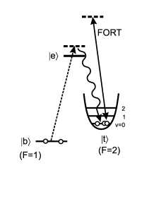
We start by briefly reviewing the generic idea of loading an optical atom trap by an optical (Raman) transition. The original proposal described in Ref. [5] is based on a -type configuration of three atomic levels, which we will indicate here by , and , as shown in Fig. 1. The levels and (for “trapping” and “bouncing” state) are electronic ground (or metastable) states, is an electronically excited state. An optical trap is created for atoms in level using the optical dipole (“light shift”) potential induced by a far off-resonance laser. Level serves as a reservoir of ultracold atoms, prepared by laser cooling. The ultracold atoms are transferred from the reservoir to the trap by a spontaneous Raman transition .
Our goal is to load a large number of atoms into a single bound state of the trapping potential, where is the vibrational quantum number. If the atoms are bosons, the transition probability into state should be enhanced by a factor , where is the occupation of the final state . If the rate at which atoms are pumped from to exceeds a threshold value, the buildup of atoms in should rapidly increase.
The Raman filling process can thus be stimulated by the matter wave in the trapped final state, leading to matter-wave amplification. The associated threshold is reached when, for some bound state , the unenhanced filling rate exceeds the unavoidable loss rate. The threshold can be lowered either by decreasing the loss rate or by increasing the overlap of wavefunctions (“Franck-Condon factor”).
Ideally, the energy separation between states and should be so large that they can be addressed separately by different lasers. Examples are alkaline earth atoms or metastable rare gas atoms. The loading scheme has been applied successfully to load metastable argon atoms into a far off-resonance lattice [15] and into a quasi-2D planar matter waveguide [8]. The two metastable states of Ar* are separated by 42 THz. In this paper we concentrate on 87Rb atoms, which we use in our experiments. Here the separation between the two hyperfine ground states is only 6.8 GHz. This requires a modification as will be discussed in Sec. III.
B The problem of photon reabsorption
It has been recognized early on that the photon emitted during the Raman process can be reabsorbed and thus remove another atom from the trap. This will obviously counteract the gain process and may even render the threshold unreachable [6]. This conclusion may be mitigated in certain situations, such as in highly anisotropic traps [16], in small traps with a size of the order of the optical wavelength [17] and in the so-called festina lente regime [18].
Our approach is to aim for a low-dimensional geometry, with at least one strongly confining direction , so that the Lamb-Dicke parameter in that direction [19, 20]. Here is the optical wavevector, is the r.m.s. width of the ground state of the trap with frequency for an atomic mass , and the recoil frequency. A low-dimensional geometry should reduce the reabsorption problem because the emitted photon has a large solid angle available to escape without encountering trapped atoms. Furthermore, we expect to compress the phase-space density by loading the low-dimensional optical trap by an evanescent-wave mirror (“atomic trampoline”), using optical pumping.
III Loading a low dimensional trap
A Inelastic evanescent-wave mirror
We now discuss the specific way in which the generic scheme discussed above is being implemented in our experiment. Our implementation is based on an evanescent-wave mirror, using explicitly the level scheme of 87Rb atoms. The role of the states and is played by the two hyperfine sublevels of the ground state , which are separated by 6.8 GHz. We take the lower level, as the “bouncing state” and the upper level, , as the “trapping state” .
We consider a configuration of laser beams as sketched in Fig. 2(a). An evanescent wave is generated by total internal reflection of a “bouncer” beam inside a prism. This bouncer is blue detuned with respect to a transition starting from the ground state, with detuning . A second laser beam, the “trapper” beam, is incident on the prism surface from the vacuum side and is partially reflected from the surface. The reflected wave interferes with the incident wave to produce a set of planar fringes, parallel to the prism surface. Note that even with 4% reflectivity of an uncoated glass surface the fringe visibility will be 0.38.
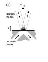
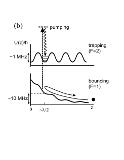
The trapper beam can be either red or blue detuned, the former having the advantage that it automatically provides transverse confinement. In Fig. 2 we sketched the situation for blue detuning, confining the atoms vertically in the intensity minima, but allowing them to move freely in the transverse direction. We assume that the loss rate due to moving out of the beam is slow compared to other loss rates, such as that due to photon scattering. Alternatively one can obtain transverse confinement by using multiple trapper beams from different directions, which interfere to yield a lattice potential. Similarly, one can create an optical lattice using multiple bouncer beams, see e.g. Fig. 4.
Ultracold atoms, in the bouncing state , are dropped onto the prism and are slowed down by the repulsive light-shift potential induced by the bouncer beam, see Fig. 2(b). If the potential is strong enough, the atoms turn around before they hit the prism and bounce back up. This is called an “evanescent-wave mirror”, or “atomic trampoline” and has been demonstrated by several groups [21, 22, 23].
We are here interested in interrupting the bouncing atoms halfway during the bounce, near the classical turning point. The interruption can occur when the atom scatters an evanescent-wave photon and makes a Raman transition to the other hyperfine ground state, . This Raman transition yields a sudden change of the optical potential, because for an atom in the detuning is larger by approximately the ground state hyperfine splitting. This mechanism has been used for evanescent-wave cooling [7]. In our case, we tailor the potentials so that the bouncer potential dominates for and the trapper for . The atom is thus slowed down by the bouncer and then transferred into the trapping potential.
As long as the probability for undergoing a Raman transition during the bounce is not too large, , the transition will take place predominantly near the turning point, for two reasons. Firstly, the atoms spend a relatively long time near the turning point. Secondly, the intensity of the optical pump (the evanescent wave) is highest in the turning point. The probability that the atoms end up in the lowest bound state of the trapping potential has been estimated to be on the order of , albeit for somewhat different geometries [9, 10]. The resulting compression of a three-dimensional cloud into two dimensions is in fact dissipative, i.e. it can increase the phase-space density.
B Phase space compression
As an illustration we give the result of a classical trajectory simulation. We start from the dimensionless phase-space distribution for the vertical motion of a single atom cooled in optical molasses, shown in Fig. 3(a). Note that denotes here the vertical velocity component and that we drop the subscript in throughout this paper. The phase-space density has been made dimensionless by dividing it by the phase-space density of quantum states. The latter is given by (states per unit area in the space), where is Planck’s constant. The distribution can be interpreted as the probability that the atom is in an arbitrary quantum state localized around .
The atom, described by the classical distribution , is assumed to enter the evanescent wave at a velocity , determined by its velocity in the molasses and the height from which it falls. Inside the evanescent wave the atom moves as a point particle along a phase-space trajectory , governed by the evanescent-wave potential.
Assuming that the saturation parameter is small, the potential is given by , where is the decay constant of the evanescent wave, with the free-space laser wavevector, the angle of incidence and the index of refraction. Similarly, the photon scattering rate is given by , with , where is the natural linewidth and is the laser detuning. Finally, the Raman transition rate is given by , with , where is the branching ratio, i.e. the probability that photon scattering leads to a Raman transition. The Raman rate gives the local probability per unit time that the trajectory is interrupted.
Due to the stochastic nature of the spontaneous Raman transition, we obtain a probability distribution over pumping coordinates where the trajectory through phase space is interrupted due to the transition, . Not surprisingly, we see in Fig. 3(b) that this distribution has the shape of a “mountain ridge” following the phase-space trajectory.
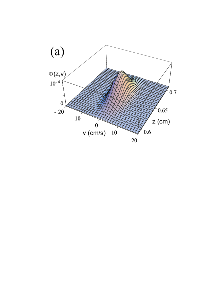
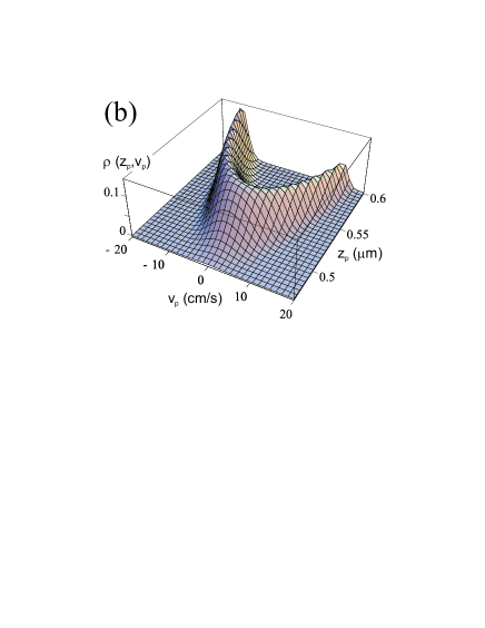
Our goal is to load the pumped atoms into a bound state of a trap near the surface. Therefore the number of interest is the peak value of , which occurs for a value of near the turning point. In Fig. 3(b) we see that the peak value of is about times higher than the initial peak value of in optical molasses (Fig. 3(a)). The peak value of 0.11 can be interpreted as the trapping probability in the ground state of the trap that collects the atoms. This value is quite comparable to previous calculations by different methods [9, 10].
The position of the turning point should be adjusted to coincide with the center of the trap, for example by adjusting or . The trapping probability can be maximized by changing the value of and/or the ratio , in such a way that . This corresponds to a situation where the probability for reaching the turning point without being optically pumped is . If the pumping rate is very high, too many atoms are pumped before they reach the turning point. If the pumping rate is very low, too many atoms bounce without being pumped at all. If the optical pumping is done by the same laser that induces the bouncing potential, we have , so that we obtain an optimum value for the detuning: . Experimentally it may be advantageous to use separate lasers for the mirror potential and for pumping so that this restriction on the detuning does not apply.
Obviously we should be somewhat careful in assigning quantitative meaning to the result of our classical simulation. In particular we should verify that the distribution is broad on the characteristic length scale of the atomic wavefunction near the turning point. The latter is determined by the slope of the bouncing potential near the turning point and is given by For the same parameters as used in Fig. 3(b) this characteristic width is nm, indeed smaller than the width of , which is nm.
IV Photon scattering
A Metastables versus alkalis
The level scheme used in the proposal of Ref. [5] was inspired by metastable rare gas or alkaline earth atoms. In those cases two (meta)stable states can usually be found with a large energy separation. This makes it relatively straightforward to separate the bouncing and trapping processes. We extend those ideas here, applying them to the typical level scheme of the alkalis. In this case the separation between two stable states is limited to the ground state hyperfine splitting.
We therefore turn to the issue of photon scattering by atoms after they have been transferred into the trap. More specifically, our main concern is scattering of bouncer light. The rate of scattering light from the trapping laser can in principle be made negligibly small by choosing a large enough detuning. This can be done because the trapping potential can be much shallower than the bouncing potential and therefore need not be -state specific. For example, if the atoms are dropped from 6 mm above the prism, their kinetic energy will be 0.6 mK, corresponding to a minimum bouncing potential of 12 MHz. For the trapping potential, on the other hand, a depth of less than 1 MHz should be sufficient, since most of the external energy of the atom has been used for climbing the bouncing potential. For the bouncing state, , the trapping potential then appears as a small ripple superimposed on the bouncing potential.
The scattering of bouncer light is more difficult to avoid. Ideally, the interaction of the atoms with the bouncer should vanish completely as soon as they are transferred into the state. In reality, however, the bouncer connects both ground states, and to the excited state through a dipole-allowed transition. We can approach the ideal situation by a proper choice of the bouncer detuning. For the simplified three-level scheme of Fig. 1, a limitation is imposed by the ground state hyperfine splitting GHz. A good distinction between the and states is only obtained if the bouncer detuning is small, . However, a very small detuning is undesirable because it leads to an increased photon scattering rate and thus heating during the bounce.
The number of photons scattered during the bounce is approximately given by where is the momentum of a Rb atom falling from a height of about 6 mm and (for an angle of incidence ). If we operate in the regime (i.e. until the turning point we have ) and set , this requires a detuning GHz. After the atom has been transferred into the trapping potential for , the detuning of the bouncer will be GHz . The trapped atoms will then scatter bouncer light at an unacceptably high rate of typically s-1.
B Dark states
The limitation imposed by the hyperfine splitting, , can be overcome by making use of dark states. This requires a more detailed look at the Zeeman sublevels of the hyperfine ground states. We consider the state and tune the bouncer laser to the D1 resonance line (795 nm, ). If this light is polarized, the selection rules require an excited state , which is not available in the manifold and so is a dark state with respect to the entire D1 line.
The state selectivity of the interaction with bouncer light now no longer depends on the detuning, but rather on a selection rule. Therefore the bouncer detuning can now be chosen large compared to . The new limitation on the detuning is the fine structure splitting of the D-lines, 7.2 THz for Rb. This reduces the photon scattering rate by 3 orders of magnitude. Note that the heavier alkalis are more favorable in this respect because of the larger fine structure splitting. The price to be paid is the restriction to two specific Zeeman sublevels and the need for a circularly-polarized evanescent wave.
V Circularly-polarized evanescent waves
In this section we briefly describe two methods for the generation of evanescent waves with circular polarization, using either a single bouncer beam or a combination of two. We also calculate the resulting photon scattering rates. There are several other ways to generate circularly-polarized evanescent waves using multiple beams. The two methods described here serve as examples.
A Single beam
A circularly-polarized evanescent wave can be obtained using a single incident laser beam if it has the proper elliptical polarization, i.e. the proper superposition of and polarization. The , or TE, mode yields an evanescent electric field parallel to the surface and perpendicular to the plane of incidence. The evanescent field of the , or TM, mode is elliptically polarized in the plane of incidence, with the long axis of the ellipse along the surface normal.
It is straightforward to calculate the input polarization that yields circular polarization in the evanescent wave. One finds that the required ellipticity of the input polarization is the inverse of the refractive index, . Here the ellipticity is defined as the ratio of the minor and major axes of the ellipse traced out by the electric field vector. The required orientation of the ellipse depends on the angle of incidence, . Close to the critical angle, , and the ellipse has its major axis perpendicular to the plane of incidence.
Following this prescription, the resulting evanescent wave will be circularly polarized, with the plane of polarization perpendicular to the surface. However, the plane of polarization is not perpendicular to the in-plane component of the -vector. Here the evanescent wave differs from a propagating wave, which has its plane of polarization always perpendicular to the -vector (and Poynting vector). For the evanescent wave the plane of circular polarization is also perpendicular to the Poynting vector. However, the Poynting vector is not parallel to the in-plane -vector, but tilted sideways by an angle given by , with the vacuum wavelength of the light. Close to the critical angle, and the plane of polarization becomes perpendicular to the in-plane wave vector, as for propagating waves.
We can estimate the photon scattering rate of an atom in the dark state , residing in the circularly polarized evanescent wave of the bouncer beam. Ideally, this scattering rate is due only to off-resonant excitation to the manifold (D2 line; 780 nm.) Choosing the bouncer detuning at 100 GHz (with respect to the D1 line) yields a scattering rate s-1. In practice there will also be scattering due to polarization impurity. For example, assuming this impurity to be 10-3, we obtain a scattering rate of s
B Two crossing -waves
Alternatively, evanescent waves of circular polarization can also be produced using two (or more) bouncer beams. If we cross two TE-polarized evanescent waves at 90∘, we will produce a polarization gradient as sketched in Fig. 4. Lines of circular polarization are now produced with the plane of polarization parallel to the surface. Lines of opposite circular polarizations alternate, with a distance of approximately between neighbouring and lines.
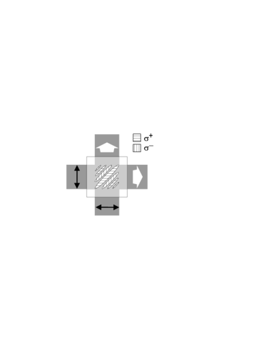
This configuration offers interesting opportunities. The light field can be decomposed into two interleaved standing wave patterns, one for and one for polarization. An atom in the state is dark with respect to the standing wave only. However it does interact with the standing wave and therefore can be trapped in its nodes. The bouncer light will thus play a double role. First it slows the atoms on their way down to the surface. Then, after the atoms have been optically pumped, the bouncer light will transversely confine the atoms. We thus expect a one-dimensional lattice of atomic quantum wires with alternating spin states, very much like a surface version of previously demonstrated optical lattices [24, 25, 26]. The transverse lattice structure may also allow the use of transverse Sisyphus cooling or Raman sideband cooling [19, 27].
It is not strictly necessary to cross the evanescent waves at a right angle. It does have the advantage that the total intensity is constant across the polarization pattern. The same could also be achieved by using counterpropagating evanescent waves with orthogonal polarizations. For any other angle, the intensity varies spatially so that the atoms bounce on a corrugated optical potential. However, even with a uniform intensity, most atoms will see a corrugated potential. The potential depends on the local polarization and on the atom’s magnetic sublevel through the Clebsch-Gordan coefficients. Only for the state the dipole potential is independent of the polarization. One could of course prepare the falling atoms in using optical pumping. The local circular polarization will tend to pump the atom into the local dark state . However the optical pumping transition has a branching ratio of only 1/6 (using a dedicated resonant pumping beam). By contrast, for an atom starting in , the branching ratio is 1/2. Therefore starting in is conceptually simple, but probably not optimal.
A disadvantage of creating circularly polarized evanescent waves on a lattice is that an additional source of photon scattering appears. We approximate the transverse potential near the minimum as a harmonic oscillator. Choosing again the bouncer detuning at 100 GHz, the harmonic oscillator frequency will be about kHz. An atom in state , in the ground state of the harmonic oscillator associated with the node has a gaussian wavefunction with wings extending into the region with light. The resulting scattering rate can be estimated as s-1, where the bouncer detuning was again chosen at 100 GHz. The scattering rate can be further suppressed to s-1 by raising the bouncer detuning to 300 GHz. For an even larger detuning the off-resonant scattering by the D2 line, , starts to dominate.
C Feasibility
We should point out that our two examples to produce circularly-polarized evanescent waves are not meant to be exhaustive. Several other methods can be devised, some being more experimentally challenging than others.
For the single-beam method the incident beam must be prepared with the correct ellipticity as well as the correct orientation. It will probably be difficult to measure the polarization of the evanescent wave directly. One should therefore prepare the incident polarization using well-calibrated optical retarders and using calculated initial settings. The fine-tuning could then be done, e.g. by optimizing the lifetime of the trapped atoms in the dark state.
For the two-beam method of Fig. 4 we have assumed for simplicity that the two interfering evanescent waves have the same decay length (i.e. the same angle of incidence) and the same amplitude. Equal decay lengths for the two waves can be enforced by making use of a dielectric waveguide [28]. Alternatively, one may deliberately give the two beams a slightly unequal decay length, and at the same time give the wave with the shorter decay length a larger amplitude. In this case there will always be one particular height above the surface where the two beams have equal amplitude, as required for interfering to circular polarization. Therefore this procedure would make the circular polarization somewhat self-adjusting. The height where circular polarization occurs is tunable by changing the relative intensity of the two beams.
Obviously, the final word on the feasibility can only be given experimentally. In our experiment we are presently pursuing a variation on Fig. 4, including the just mentioned self-adjusting properties.
VI Conclusion
In conclusion, we have shown that inelastic bouncing on an evanescent-wave mirror (“atomic trampoline”) is a promising method for achieving high phase-space density in low-dimensional optical traps. The phase space compression is achieved by means of a spontaneous Raman transition, which is highly spatially selective for atoms near the turning point of the evanescent-wave mirror potential.
We have extended previous work based on the level schemes of metastable rare gas atoms for application to alkali atoms. This requires suppression of the high photon scattering rate, resulting from the relatively small ground hyperfine splitting in the alkalis. We have shown how the photon scattering rate can be reduced by several orders of magnitude, by trapping the atoms in dark states. This requires the use of circularly-polarized evanescent waves, which can be generated by several methods as discussed. If built up from multiple beams, the evanescent field may play a double role, generating a bouncing as well as a trapping potential. This could lead to an array of quantum wires for atoms.
VII Acknowledgments
This work is part of the research program of the “Stichting voor Fundamenteel Onderzoek van de Materie” (Foundation for the Fundamental Research on Matter) and was made possible by financial support from the “Nederlandse Organisatie voor Wetenschappelijk Onderzoek” (Netherlands Organization for the Advancement of Research). The research of R.S. has been made possible by financial support from the Royal Netherlands Academy of Arts and Sciences.
REFERENCES
- [1] M.H. Anderson, J.R. Ensher, M.R. Matthews, C.E. Wieman and E.A. Cornell, Science 269, 198 (1995).
- [2] K.B. Davis, M.-O. Mewes, M.R. Andrews, N.J. van Druten, D.S. Durfee, D.M. Kurn and W. Ketterle, Phys. Rev. Lett. 75, 3969 (1995).
- [3] C. Bradley, C. Sackett, and R. Hulet, Phys. Rev. Lett. 78, 985 (1997).
- [4] M.-O. Mewes, M.R. Andrews, D.M. Kurn, D.S. Durfee, C.G. Townsend and W. Ketterle, Phys. Rev. Lett. 78, 582 (1997).
- [5] R. Spreeuw, T. Pfau, U. Janicke, and M. Wilkens, Europhys. Lett. 32, 469 (1995).
- [6] M. Olshanii, Y. Castin, and J. Dalibard, in Laser Spectroscopy XII, edited by M. Inguscio, M. Allegrini, and A. Sasso (World Scientific, Singapore, 1996), p. 7.
- [7] Y. B. Ovchinnikov, I. Manek, and R. Grimm, Phys. Rev. Lett. 79, 2225 (1997).
- [8] H. Gauck, M. Hartl, D. Schneble, H. Schnitzler, T. Pfau and J. Mlynek, Phys. Rev. Lett. 81, 5298 (1998).
- [9] P. Desbiolles and J. Dalibard, Optics Comm. 132, 540 (1996).
- [10] W. Power, T. Pfau, and M. Wilkens, Optics Comm. 143, 125 (1997).
- [11] T. Pfau and J. Mlynek, OSA Trends Optics Photonics Series 7, 33 (1997).
- [12] E. Hinds, M. Boshier, and I. Hughes, Phys. Rev. Lett. 80, 645 (1998).
- [13] A.I. Safonov, S.A. Vasilyev, I.S. Yasnikov, I.I. Lukashevich and S. Jaakkola, Phys. Rev. Lett. 81, 4545 (1998).
- [14] C. Henkel and J.-Y. Courtois, Eur. Phys. J. D 3, 129 (1998).
- [15] T. Müller-Seydlitz, M. Hartl, B. Brezger, H. Hänsel, C. Keller, A. Schnetz, R.J.C. Spreeuw, T. Pfau and J. Mlynek, Phys. Rev. Lett. 78, 1038 (1997).
- [16] Y. Castin, J. Cirac, and M. Lewenstein, Phys. Rev. Lett. 80, 5305 (1998).
- [17] U. Janicke and M. Wilkens, Europhys. Lett. 35, 561 (1996).
- [18] J. Cirac, M. Lewenstein, and P. Zoller, Europhys. Lett. 35, 647 (1996).
- [19] V. Vuletić, C. Chin, A. J. Kerman, and S. Chu, Phys. Rev. Lett. 81, 5768 (1998).
- [20] I. Bouchoule, H. Perrin, A. Kuhn, M. Morinaga and C. Salomon, Phys. Rev. A 59, R8 (1999).
- [21] M. Kasevich, D. Weiss, and S. Chu, Optics Lett. 15, 607 (1990).
- [22] K. Helmerson, S. Rolston, L. Goldner, and W. Phillips, in Optics and interferometry with atoms (book of abstracts, WE Heraeus Seminar, Konstanz, 1992, unpublished).
- [23] C.G. Aminoff, A.M. Steane, P. Bouyer, P. Desbiolles, J. Dalibard and C. Cohen-Tannoudji, Phys. Rev. Lett. 71, 3083 (1993).
- [24] P.S. Jessen, C. Gerz, P.D. Lett, W.D. Phillips, S.L. Rolston, R.J.C. Spreeuw and C.I. Westbrook, Phys. Rev. Lett. 69, 49 (1992).
- [25] P. Verkerk, B. Lounis, C. Salomon, C. Cohen-Tannoudji, J.-Y. Courtois and G. Grynberg, Phys. Rev. Lett. 68, 3861 (1992).
- [26] P. Jessen and I. Deutsch, Adv. At. Mol. Opt. Phys. 37, 95 (1996).
- [27] S.E. Hamann, D.L. Haycock, G. Klose, P.H. Pax, I.H. Deutsch and P.S. Jessen, Phys. Rev. Lett. 80, 4149 (1998).
- [28] W. Seifert, R. Kaiser, A. Aspect, and J. Mlynek, Optics Comm. 111, 566 (1994).