First-order interference of nonclassical light
emitted spontaneously at different times
Abstract
We study first-order interference in spontaneous parametric down-conversion generated by two pump pulses that do not overlap in time. The observed modulation in the angular distribution of the signal detector counting rate can only be explained in terms of a quantum mechanical description based on biphoton states. The condition for observing interference in the signal channel is shown to depend on the parameters of the idler radiation.
pacs:
PACS Number: 42.50.Dv, 03.65.BzNonclassical interference is one of the most remarkable phenomena of quantum optics. In particular, it can be observed in experiments with spontaneous parametric down conversion (SPDC) [1], a nonlinear optical process in which higher-energy pump photons are converted into pairs of lower-energy photons (usually called signal and idler) inside a crystal with quadratic nonlinearity. It has been shown that the state of the signal-idler photon pair is entangled in space-time, polarization, or both [2]. Due to the nonclassical correlation between the signal and the idler photons emitted in SPDC, the term “biphoton” has been suggested [3]. Many experiments made use of SPDC to demonstrate fascinating topics in quantum optics, such as Bell’s inequalities violation, quantum communication, quantum teleportation, etc [4]. All these experiments belong to basically the same category: quantum interference. The existence of the SPDC interference enables one to monitor the structure of biphoton fields. This effect can be used in quantum communication, computation, and cryptography [5].
Among the variety of interference experiments, there is a large group of works where first-order interference is observed in signal or idler SPDC radiation emitted from spatially separated domains [6, 7, 8]. This kind of interference is nonclassical. Indeed, each of the signal and idler beams has noise (thermal) statistics; from a classical viewpoint, spatially separated SPDC sources should exhibit no interference pattern in the signal or idler beams. One cannot observe stable first-order interference of light emitted by independent classical thermal sources such as, for instance, two similar light-emitting diodes[9]. To explain the interference observed for SPDC radiation, one should take into account that each signal or idler photon is generated not from some particular point but from the whole volume with quadratic nonlinearity, pumped by a coherent pump. And indeed, in this case one cannot tell whether a photon was born at one point or another - the interference is observed in agreement with Feynman’s indistinguishability criterion[10]. Another interesting feature of the first-order interference of SPDC is that it depends on the phases of pump, signal, and idler waves, and one can speak of “three-frequency” interference [11]. Moreover, the condition for the interference to be observed in, say, signal radiation depends on the parameters of the idler radiation[8].
In this Letter, we report an experimental observation of a novel type of quantum interference, in which the sources of two-photon radiation are separated not in space but in time, as SPDC is generated from a train of coherent femtosecond pulses [12]. Depending on the experimental conditions, interference can be observed either in the angular distribution of the signal intensity (first-order interference measured by single-detector method) or in the coincidences of photocounts from the detectors registering the signal and the idler radiation (second-order interference measured by two-detector method). In this paper, we focus on the first-order interference; second-order interference effects will be discussed elsewhere.
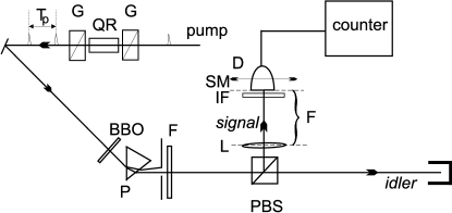
Let us consider type-II SPDC field [13] generated in a crystal of length from a train of two short pump pulses. The signal radiation is separated from the idler one (Fig. 1) and its intensity is measured by a detector that selects a sufficiently narrow frequency band and a sufficiently small solid angle. (The meaning of the words ‘sufficiently small’ will be clear from further consideration.)
The pump field dependence on time can be represented in the form
| (1) |
where is the pump group velocity, is the envelope, and is the pump central frequency. It is supposed that the spectral band of the pump is much less than (quasi-monochromatic case). If the pump consists of two identical pulses separated in time by , then , where is a single-pulse envelope.
In the first order perturbation theory, the quantum state of SPDC is given by [1]
| (2) |
where is the two-photon spectral function,
| (4) | |||||
and the notation means a two-photon state in the modes .
Since the pump pulse is bounded in time, the integration over can be extended to infinite limits. As a result, it gives the Fourier transform of the pump envelope, , which in the cw case becomes a -function, . We obtain
| (6) | |||||
where, for example, and are the transverse and longitudinal components of the signal wavevector, respectively. For a two-pulse pump, the envelope spectrum is , with denoting the Fourier transform of the single-pulse envelope.
The probability of detecting a biphoton is . Since we are dealing with a two-photon state, the probability of a photocount from the signal detector is calculated by integrating over all idler modes. Thus, the photon counting rate in the signal detector is
| (7) | |||||
| (8) | |||||
| (9) | |||||
| (10) |
where is the dispersion dependence for the idler beam and , with denoting the signal angle of scattering.
The cosine modulation in Eq. (10) will not be averaged out by the integration over if the squared sinc function is much narrower than this modulation. In this case the squared sinc acts as a delta-function in the integral, thus
| (12) | |||||
Clearly, Eq.(12) gives a modulated structure for the counting rate of the signal detector. This modulation can be observed in several ways. One can observe interference by varying or by varying , which both enter the squared cosine in Eq.(12). In this work, however, we obtain the modulation by varying the signal angle of scattering. This is possible since , hence , actually depends on . This can be shown by expanding in the vicinity of .
The sinc-square function in the integral (10) is much narrower than the cosine modulation if
| (13) |
For near-collinear scattering, we can take approximately . Hence, we obtain the following condition for observing the first-order interference in SPDC from a two-pulse pump:
| (14) |
The other condition is the assumption we have used when obtaining Eq. (12): the signal detector should select a sufficiently narrow frequency band and a sufficiently small solid angle. Indeed, the interference structure will be wiped out if Eq. (12) is integrated over a broad band of signal frequencies or angles of scattering. Thus, the requirement to the frequency band of the signal detector is
| (15) |
In the experiment, the pump is the frequency-doubled radiation from a mode-locked Ti:Sapphire laser with initial central wavelength nm. After frequency doubling, the pulse duration is fsec, and the repetition rate is MHz. The pump pulse is then fed into the polarization pulse splitter consisting of two Glan prisms G and a set of quartz rods QR placed between the prisms (Fig. 1). The axes of the Glan prisms are parallel to the pump polarization. The ‘fast’ and ‘slow’ axes of the quartz rods lie in the plane normal to the pump beam and are directed at to the pump polarization. Due to the birefringence of the quartz rods, at the output of the polarization splitter each pump pulse is transformed into two pulses that have equal amplitudes but are delayed in time with respect to one another by , where is the total length of the quartz rods and , are group velocities of the ordinary and extraordinary waves in quartz at the pump wavelength (nm). The SPDC radiation is generated in a BBO crystal cut for collinear frequency-degenerate type-II phase matching. The SPDC radiation is separated from the pump radiation by means of a prism (P) and a pinhole. A polarizing beam splitter (PBS) separates the signal radiation from the idler one, and the idler beam is discarded. The detector (an avalanche diode operating in the Geiger mode) is placed at the focal plane of a lens (F = cm), so that the transverse displacement of the detector is proportional to the angle of scattering, . In front of the detector, we place one of the three narrow-band filters (IF) with central wavelength nm and bandwidths , and nm, respectively, for different measurements. The intensity of the signal radiation is measured as a function of the angle of scattering, . The angle is scanned by using a step motor (SM) that moves the detector in the focal plane of the lens. The parameters are bandwidth of the filter, , and the time delay between the two pump pulses, , which is varied by using quartz rods with total length , , and mm, corresponding to the delays , , and fsec, respectively.
The fact that each pair of pulses is actually repeated at a rate of 90 MHz leads to a fine structure in the single-counting distribution (12), which is much narrower than the bandwidth of the filters we use in our experiment. Therefore, it is not observable.
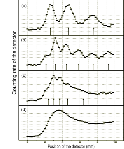
To test Eq. (14), we use a BBO crystal of length mm to generate SPDC. In Fig. 2, the intensity is plotted versus the detector displacement for all three delays . All dependencies are obtained with the nm interference filter. Note that in this case, condition (15) is satisfied for all three delays: fs. However, the interference visibility in all plots is different. The highest visibility of the interference pattern is observed for the smallest time interval between the pulses, fsec, with [Fig. 2(a)]. For the intermediate delay, fsec, the interference pattern is observed with lower visibility [Fig.2(b)]. In this case, . Evidently, Eq. (14) is not satisfied for the largest delay fsec (), therefore, in this case the interference structure completely vanishes [Fig. 2(c)]. For comparison, the angular spectrum of SPDC in the case of a single-pulse pump is shown in Fig.2(d). In agreement with Eq. (12), the modulation period is larger for smaller delays. In all experimental plots, positions of the oscillation peaks are determined by the delay introduced between the pump pulses, in perfect agreement with the theoretical calculation [shown by arrows in Figs. 2(a),(b),(c)]. However, the theory discussed above does not give explicit description of the observed asymmetry of the angular spectral envelope. In this Letter, we only focus on the interference modulation; the shape of the angular spectrum envelope will be considered elsewhere.
The spectral width of the filter, , has a strong influence on the interference pattern. Changing the filter bandwidth from nm to nm, we observed a considerable decrease of the visibility. At nm, no interference structure was observed, in agreement with condition (15).
Let us give a physical interpretation of condition (14) for observing the first-order interference in SPDC signal radiation from a two-pulse pump. Note that although it is the signal radiation that one detects, Eq. (14) contains only the pump and the idler parameters.
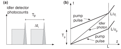
Considering only the signal radiation, it would seem that the only condition for the first-order interference to take place is Eq. (15), which states that the filter inserted in front of the signal detector should have smaller bandwidth compared to the pump spectrum modulation. Indeed, if the signal photon wavepackets are spread in time by more than , the signal photons born from different pump pulses are at first sight indistinguishable. However, it is worth remembering that the indistinguishability criterion should be understood as indistinguishability in principle. In principle, we could equip our setup by an idler detector with a broad-band filter and register photocounts from the idler detector (Fig. 3). Then for each signal photon, detection of its twin idler photon is well localized in time with respect to the pump pulses, which could mean that we can always distinguish between a pair born from the first pulse and a pair born from the second pulse. Let us recall now that the BBO crystal has finite length . Then a photocount in the idler detector can appear delayed from the corresponding pump pulse by any time (Fig. 3). Idler photocounts from different pump pulses become indistinguishable if , and we obtain the second necessary condition for the interference, which is Eq. (14).
There is an analogy between the first-order interference observed for SPDC generated from two spatially separated domains and for SPDC generated from two separate pump pulses. Indeed, condition (14) ensures that the crystal is long enough so that an idler photon generated by the first pump pulse can meet the second pulse (see Feynman diagram in Fig. 3). In the case of spatially separated SPDC sources, first-order interference [6, 8] is possible when idler waves propagate through both spatial domains where SPDC take place [14]. Similarly to Ref. [8], where the effect has simple explanation in terms of the pump angular spectrum, here it can be explained by the cosine modulation of the pump frequency spectrum. Condition (14) has the following spectral interpretation: the typical scale of the pump spectrum modulation should be much larger than the width of the idler radiation spectrum, which is determined by the length of the crystal [1].
In conclusion, we have demonstrated the first-order interference of nonclassical light generated from two pump pulses well separated in time. The interference is explained by a quantum mechanical calculation in terms of biphoton states. The interference pattern is observed in the angular distribution of the signal intensity. Interference takes place if the following condition is satisfied: the time indeterminacy of the delay between the idler photon and the corresponding pump pulse is much larger than the time interval between the pump pulses. From the spectral viewpoint, this condition means that the modulation of the pump spectrum, determined by the distance between the pulses, should be much larger than the width of the idler radiation spectrum from a cw pump, determined by the crystal length. Thus, the interference visibility is sensitive to the crystal length. It is also sensitive to the spectral width of the narrow-band filter used for the frequency selection of the signal radiation.
This work was supported in part by The Office of Naval Research and an ARO-NSA grant. MVC and SPK also acknowledge partial support from the Russian Foundation for Basic Research, grant No. 97-02-17498.
REFERENCES
- [1] D.N. Klyshko, Photons and Nonlinear Optics (Gordon & Breach, New York, 1988).
- [2] Y.H. Shih, A.V. Sergienko, M.H. Rubin, T.E. Kiess, and C.O. Alley, Phys. Rev. A 50, 23 (1994); Y.H. Shih and A.V. Sergienko, Phys. Rev. A 50, 2564 (1994); M.H. Rubin, D.N. Klyshko, Y.H. Shih, and A.V. Sergienko, Phys. Rev. A 50, 5122 (1994); P.G. Kwiat, K. Mattle, H. Weinfurter, A. Zeilinger, A.V. Sergienko, and Y.H. Shih, Phys. Rev. Lett. 75, 4337 (1995).
- [3] D.N. Klyshko, Soviet Physics-JETP 56, 755 (1982).
- [4] Y.H. Shih and C.O. Alley, Phys. Rev. Lett. 61, 2921 (1988); K. Mattle, H. Weinfurter, P.G. Kwiat, and A. Zeilinger , Phys. Rev. Lett. 76, 4656 (1996); J. Brendel, N. Gisin, W. Tittel, and H. Zbinden, Phys. Rev. Lett. 82, 2594 (1999); D. Bouwmeester, J.-W. Pan, K. Mattle, M. Eidl, H. Weinfurter, and A. Zeilinger, Nature 390, 575 (1997); D. Boschi, S. Branca, F. De Martini, L. Hardy, and S. Popescu, Phys. Rev. Lett. 80, 1121 (1998).
- [5] C.H. Bennett and S.J. Wiesner, Phys. Rev. Lett. 69, 2881 (1992); A.K. Ekert, J.G. Rarity, P.R. Tapster, and G.M. Plama, ibid. 69, 1293 (1992); J.D. Franson and H. Ilves, J. Mod. Opt. 41, 2391 (1994).
- [6] X.Y. Zou, L.J. Wang, and L. Mandel, Phys. Rev. Lett., 67, 318 (1991).
- [7] T.J. Herzog, J.G. Rarity, H. Weinfurter, and A. Zeilinger, Phys. Rev. Lett. 72, 629 (1994).
- [8] A.V. Burlakov, M.V. Chekhova, D.N. Klyshko, S.P. Kulik, A.N. Penin, Y.H. Shih, and D.V. Strekalov, Phys. Rev. A 56, 3214 (1997).
- [9] In this case, even if a narrow-band filter is used, the interference pattern is stable only for the time , where is the frequency bandwidth of the filter
- [10] R. Feynman, R. Leighton, and M. Sands, The Feynman Lectures on Physics, Vol.III, Addison Wesley, Reading (1965).
- [11] A.V. Burlakov, S.P. Kulik, A.N. Penin, and M.V. Chekhova, JETP 86, 1090 (1998).
- [12] Second-order interference effects from a pump consisting of several short pulses were described in T.E. Keller, M.H. Rubin, and Y.H. Shih, Phys. Lett. A 244, 507 (1998) and observed in Y.-H. Kim, M.V. Chekhova, S.P. Kulik, and Y.H. Shih, Phys. Rev. A 60, R37 (1999).
- [13] In type-I SPDC, the signal and idler photons have the same polarization, in type-II SPDC they have orthogonal polarization.
- [14] Of course we do not mean that the idler photons created from the first pulse somehow influence the SPDC process from the second pulse, like in the spatial case the idler radiation emitted from the first domain does not influence the process in the second domain. The output photon numbers in both signal and idler modes are so small that all induced effects can be neglected.