Quantum fluctuations for drag free geodesic motion
Abstract
The drag free technique is used to force a proof mass to follow a geodesic motion. The mass is protected from perturbations by a cage, and the motion of the latter is actively controlled to follow the motion of the proof mass. We present a theoretical analysis of the effects of quantum fluctuations for this technique. We show that a perfect drag free operation is in principle possible at the quantum level, in spite of the back action exerted on the mass by the position sensor.
PACS: 42.50 Lc; 04.80.Cc; 07.50-e
The Galilean principle of the universality of free fall has for a long time had a limited accuracy due to technical difficulties. The effect of air drag on falling bodies, the main of these difficulties, was already discussed at length by Galileo and Newton [1, 2]. Nowadays this effect may be mastered either by an active control of the falling bodies or by letting the fall take place in a vacuum drop tower. Using an active control greatly reduces the vacuum requirement while allowing a test accuracy of [3]. This accuracy does not reach the level of torsion balance experiments [4, 5, 6] but it may do so in the future with the additional use of a vacuum drop chamber [7]. The accuracy of the measurement of relative acceleration of freely falling bodies may thus reach with a measurement time of s corresponding to a fall of m in the Bremen drop tower [8].
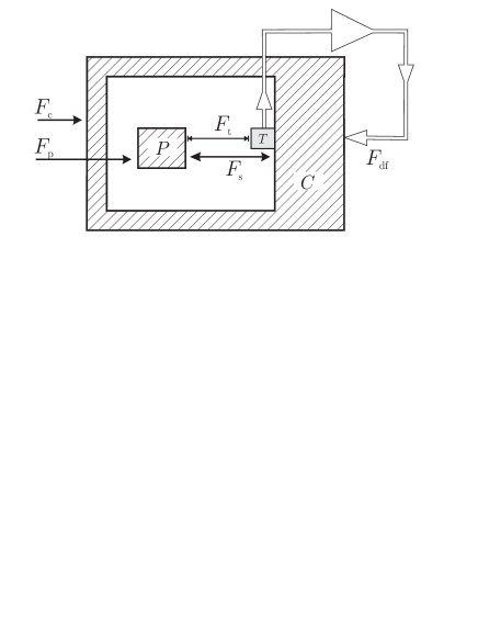
The use of drag free technique has also been proposed for ultra high accuracy satellite tests of the equivalence principle [9, 10]. When such a technique is used, the freely falling proof mass is protected from the non gravitational perturbations like residual air drag, radiation pressure, et cetera by the satellite and its relative motion with respect to the satellite is monitored by a high sensitivity position sensor. The effect of these environmental perturbations on the satellite motion is then finely compensated through the action of thrusters. In the present paper, we evaluate the ultimate limits of the drag free technique. We study the residual motion of a proof mass protected from environmental perturbations by a cage, the motion of which is itself actively controlled to follow the geodesic motion of the proof mass. These questions have already been addressed from a classical point of view [11, 12] which is sufficient for assessing the performance of real existing devices.
It is however very interesting to address the same questions in the context of quantum measurement theory, at least as questions of principle. In a drag free technique, the proof mass is continuously monitored by a position sensor and it is therefore submitted to the back action of the sensor [13]. When the sensibility of the sensor is improved, the back action noise is expected to increase. It seems therefore difficult to have at the same time a highly sensitive tracking and an unperturbed geodesic motion of the proff mass. In fact, this difficulty may be circumvented by the use of active techniques. We show in the present paper that drag free operation may be in principle performed at the quantum level with the proof mass following a nearly ideal geodesic trajectory.
We consider in this paper a cold damped capacitive sensor developed at ONERA for ultrasensitive accelerometry [14, 15, 16]. The present analysis heavily relies on previous studies of quantum and thermal fluctuations in such a device [17, 18, 19]. In particular the analysis of the position sensor will simply be taken from these references. The new result of the present paper will concern the drag free system with the measured acceleration between the proof mass and the cage used as an error signal to servo control the cage motion. The drag free system is sketched on figure .
The mechanical response of the system in the absence of servo control can be written in term of a mechanical impedance matrix
| (1) |
Throughout the paper the descriptions are given in the frequency domain and the quantum convention is used for the Fourier transform. The electronics convention may be recovered by substituting to . All physical observables are represented as non commutative quantum operators.
The proof mass velocity and the cage velocity are determined through this equation to the total forces and acting on the two objects
| (2) | |||||
| (3) |
Here is external force acting on the proof mass despite the screening (for example the gravitational force) and is the external force acting on the cage (including all the environmental perturbations). is the force exerted on the proof mass and on the cage through the separating space between them (for example the Langevin force associated with residual gas). is the back action force exerted by the electromechanical transducer used to measure the relative position between the proof mass and the cage. The action and reaction forces have been treated as equal, which amounts to neglect the delays at the low mechanical frequencies considered here.
is the mechanical impedance of the free proof mass, that is a mass which would be neither perturbed by the environmental forces screened by the cage nor disturbed by its coupling to a sensor. It takes in particular into account the inertial mass and the dissipative effects associated with the unscreened forces. In this sense what we call in the following the free motion of the proof mass is described by the equation
| (4) |
When quantum fluctuations are taken into account (see for example [20, 21]) this equation is known to include the fluctuations associated with Schrodinger equation at the limiting case of a vanishingly small dissipation [22]. is similarly the impedance of cage in the absence of coupling to the proof mass and to the transducer. Finally corresponds to the interaction between the proof mass and the cage through the restoring force, damping associated with residual gases, back action forces due to the presence of the position sensor et cetera.
The mechanical impedances and force fluctuations are related through the fluctuation dissipation relations initially discovered by Einstein in his analysis of Brownian motion [23]. These relations are known as Nyquist relations for electrical systems [24] and they are written below with quantum fluctuations accounted for [25, 26]. The dissipative part of the susceptibility functions is directly related to the commutator of the quantum force fluctuations [22]. Then force fluctuations are characterized by a noise spectrum with its well-known expression for a thermal equilibrium at a temperature
| (5) | |||
| (6) | |||
| (7) |
The symbol ‘’ denotes a symmetrized product for quantum operators (used to get rid of the ordering ambiguity), is the Boltzmann constant and the temperature. We have introduced an effective temperature with representing exactly the energy per mode of the fluctuations. This energy reproduces the classical result at the high temperature limit and the zero point energy at zero temperature.
The motion sensor is a capacitive transducer designed to detect the relative acceleration between the cage and the proof mass. Its operation and performances have been described in detail elsewhere [14, 15, 16]. We recall here the properties of this sensor when the various parameters are optimized [17, 19].
The sensor measures the velocity difference between the cage and the proof mass
| (8) |
Its performance can be discussed by introducing an estimator representing the velocity as it may be inferred from the output of the sensor. After an appropriate scaling this estimator is the sum of the velocity signal and of a sensing error
| (9) |
The sensing error and the back action force exerted by the transducer onto the proof mass are the main parameters of interest for evaluating the performance of the sensor. Here we use their expressions taken from [17, 19] and discuss the drag free system.
In the drag free system the measured velocity is used as an error signal to servo control the motion of the cage. It is worth recalling that this error signal has been obtained after a preamplification stage with a large gain [18]. As shown in [19], we may greatly simplify the analysis of the whole system by considering the further amplification stages as noiseless. This is true in particular for the amplifications used in the feedback loops. Hence, we may write the servo control force acting on the cage as merely proportional to the velocity estimator
| (10) |
The factor is the gain of the servo loop and it corresponds to an effective mechanical impedance. With the feedback in operation, the equations of motion are now written
| (11) |
In the limit of a large servo loop gain, the solution of these equations is read
| (12) | |||||
| (13) | |||||
| (14) |
These quantum equations have exactly the same form as in a classical analysis of fluctuations. As a first result, this proves that the drag free technique is also effective when quantum fluctuations are taken into account. But it is more interesting to consider these equations as describing the ultimate performance of the system as it would be limited by quantum fluctuation processes and to address in this manner the questions asked in the introduction.
As already explained, the free motion of the proof mass corresponds to the unperturbed equation (4). This free motion is recovered in (14) superimposed to perturbations having various origins. represents the Langevin forces associated with the dissipative part of the impedance characterizing the coupling between the proof mass and the cage. is the back action exerted by the sensor on the proof mass and is the sensing error which appears multiplied by the mechanical impedance . If we concentrate on questions of principle these terms can be arbitrarily reduced by tailoring the impedances and the associated fluctuations. Quantum mechanics does not prevent a perfect drag free operation.
In the following we focus our attention on a simple and realistic treatment of the amplifier as a phase independent device characterized by an equivalent noise temperature and noise impedance [18]. In this situation, the back action noise and the sensing error can be written as
| (15) | |||||
| (16) | |||||
| (17) |
They vary as conjugated noises as functions of the mechanical impedance and of the dimensionless ratio which represents the impedance matching between the amplifier and the electromechanical transducer [19]. is the effective temperature characterizing the preamplifier noise. It depends on a temperature and the frequency of operation of the electrical detection circuit. The latter lies in the 100kHz range that is at much higher frequencies than the mechanical frequencies of interest. The correlation function of the proof mass velocity (14) is thus
| (18) | |||||
| (19) |
The first line represents the free motion of the proof mass and the second line the noises added respectively by the three additional terms in (14). The noise added to the free motion of the test mass by the drag free system has a minimum level when the impedances are matched so that . The noise thus reaches its minimum value
| (20) | |||||
| (21) |
Equation (21) describes in a quantitative manner the ultimate performance of the drag free system as far as the residual motion of the proof mass is concerned. The added noise contains the fluctuations corresponding to the Langevin force associated with the dissipation between the proof mass and the cage and a second term having the same order of magnitude when the equivalent temperature and are equal. In fact it may even be larger in this situation if the impedance is mainly reactive. Note that this feature makes a difference with the previously studied case where the accelerometer was used for measuring the force acting on the proof mass [19]. In the previous case, the last term was reduced by a factor of the order of the frequency transposition ratio . Here in contrast, we are concerned with the real motion of the proof mass and not only with the accelerometry signal used as error signal. We do not benefit of this frequency transposition ratio for the motion control. To illustrate this point we rewrite the velocity noise (21) with the assumption of a zero temperature that is to say a temperature small with respect to all frequencies of interest
| (22) |
The frequency transposition gives a large weight to the noise added by the servo control. The technique of frequency transposition so well adapted to the measurement of a force with the accelerometer is of no help for a drag free operation.
Coming back to the general case we may also write the velocity noise for the actively controlled cage motion. The formula equivalent to (19) is read as
| (23) | |||||
| (24) |
It can be used to discuss the ultimate performance of the drag free system when the emphasis is put on the geodesic motion of the cage. In this case a different value of the impedance matching parameter has to be chosen in order to optimize the performance of the system and this choice leads to a minimum velocity noise for the cage
| (25) | |||||
| (26) |
Active techniques are now used in the operation of gravitational wave
detection with interferometers [27, 28], in particular for
improving isolation of the mirors from the ground motion. The motion of the
first stage of the isolator is measured with accelerometers and compensated
with feedback action. In the last stage, servo control is also used to
perform the final positioning of the miror. The discussions presented in the
present paper could be applied to analyse the limits of these techniques.
Acknowledgments
We wish to thank Francesca Grassia, Pierre Touboul and Philippe Tourrenc for stimulating discussions.
REFERENCES
- [1] Galileo Galilei Discorsi e dimostrazioni matematiche intorno a due nouve scienze (1638)
- [2] Isaac Newton Philosophiae naturalis principia mathematica (1686)
- [3] T.M. Niebauer, M.P. McHugh and J.E. Faller, Phys. Rev. Lett. 59 (1987) 609
- [4] P.G. Roll, R.V. Krotkov and R.H. Dicke, Annals of Physics 26 (1964) 442
- [5] V.B. Braginsky and V.L. Panov, Sov. Phys. JETP 34 (1972) 463
- [6] E.G. Adelberger et al, Phys. Rev. Lett. 59 (1987) 849
- [7] K. Kuroda and N. Mio, Phys. Rev. Lett. 62 (1989) 1941
- [8] H. Dittus et al, Class. Quantum Grav. 13 (1997) A43 (in [9])
- [9] Special issue “Fundamental Physics in Space”, Class. Quantum Grav. 13 (1996) A1-A315
- [10] Special issue “International LISA Symposium”, Class. Quantum Grav. 14 (1997) 1397-1585
- [11] Y. Jafry, Class. Quantum Grav. 13 (1996) A179 (in [9])
- [12] D.B. De Bra, Class. Quantum Grav. 14 (1997) 1549 (in [10])
- [13] V.B. Braginsky and F.Ya. Khalili, Quantum Measurement (Cambridge University Press, 1992)
- [14] A. Bernard and P. Touboul, The GRADIO accelerometer: design and development status, Proc. ESA-NASA Workshop on the Solid Earth Mission ARISTOTELES, Anacapri, Italy (1991).
- [15] P. Touboul et al., Continuation of the GRADIO accelerometer predevelopment, ONERA Final Report 51/6114PY, 62/6114PY ESTEC Contract (1992, 1993)
- [16] E. Willemenot, Pendule de torsion à suspension électrostatique, très hautes résolutions des accéléromètres spatiaux pour la physique fondamentale, Thèse de l’Université Paris-Sud (1997)
- [17] F. Grassia, Fluctuations quantiques et thermiques dans les transducteurs électromécaniques, Thèse de Doctorat de l’Université Pierre et Marie Curie (1998)
- [18] J-M. Courty, F. Grassia and S. Reynaud, Europhys. Lett. 46 (1999) 31
- [19] F. Grassia, J-M. Courty, S. Reynaud and P. Touboul , to appear in Eur. Phys. J. D, preprint xxx quant-ph/9904073
- [20] S. Reynaud, A. Heidmann, E. Giacobino and C. Fabre, Progress in Optics XXX ed. E.Wolf (Elsevier, 1992) 1
- [21] M.F. Bocko and R. Onofrio, Rev. Mod. Phys. 68 (1996) 755
- [22] M.T. Jaekel and S. Reynaud, J. de Physique I-3 (1993) 1
- [23] A. Einstein, Annalen der Physik 17 (1905) 549
- [24] H. Nyquist, Phys. Rev. 32 (1928) 110
- [25] H.B. Callen and T.A. Welton, Phys. Rev. 83 (1951) 34
- [26] E.M. Lifshitz and L.P. Pitaevskii, Landau and Lifshitz, Course of Theoretical Physics, Statistical Physics Part 2 (Butterworth-Heinemann, 1980) ch. VIII
- [27] S.J. Richman et al, Rev. Sci. Instr. 69 (1998) 2531
- [28] G. Losurdo et al, Rev. Sci. Instr. 70 (1999) 2507