Thermal noise of a plano-convex mirror
Abstract
We study theoretically the internal thermal noise of a mirror coated on a plano-convex substrate. The comparison with a cylindrical mirror of the same mass shows that the effect on a light beam can be reduced by a factor 10, improving the sensitivity of high-precision optical experiments such as gravitational-wave interferometers.
PACS : 05.40.Jc, 04.80.Nn, 43.40.+s
Thermal noise is a basic limit in many precision measurements[1]. For example, the sensitivity in interferometric gravitational-wave detectors[2, 3] is limited by the Brownian motion of the suspended mirrors. This thermally excited motion can be decomposed into suspension and internal noises. The former refers to the motion of the center of mass of the mirrors and it has been extensively studied both theoretically[4, 5] and experimentally[6, 7, 8, 9]. Internal noise is due to thermally induced deformations of the mirror surface and constitutes the main limitation of gravitational-wave detectors in the intermediate frequency domain. It has thus been studied theoretically for mirrors corresponding to the VIRGO and LIGO gravitational-wave observatories, either by a decomposition of the motion over acoustic modes[10, 11] or by a direct approach based on the fluctuation-dissipation theorem[12, 13]. The normal-mode expansion shows that the internal thermal noise may depend on the mirror shape and on the spatial matching between light and acoustic modes. For example, a bar-shaped cylindrical mirror is less noisy than a gong-shaped one. A slight noise reduction has also been obtained by moving the light beam off center. These works however deal with standard cylindrical shapes although there is no evidence that such a geometry is the best candidate to reach low thermal noise.
In this paper, we study an alternative geometry in which the mirror is coated on the plane side of a plano-convex substrate. Such a plano-convex geometry has been extensively studied for mechanical resonators with high quality factors[14]. Acoustic modes are confined near the central axis of the resonator and their spatial structure can be described by analytical expressions similar to gaussian optical modes of a Fabry-Perot cavity[14, 15, 16]. We show that this geometry leads to a drastic reduction of the thermal noise. We first recall the effect of mirror deformations on the light reflected by the mirror. We then determine the mirror motion induced by thermal excitation and show that the effect on light at low frequency can be expressed in terms of an effective susceptibility which takes into account every acoustic mode and its coupling to the light. We compare the effect of thermal noise to the one obtained with a cylindrical mirror of the same mass. We finally determine the noise reduction obtained by moving the light beam off center and we show that a global noise reduction of 10 can be reached.
I Effect of thermal noise on light
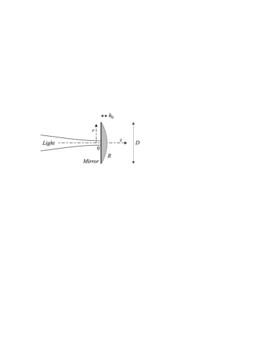
In a gravitational-wave interferometer, the thermal noise of the mirrors has a similar effect as a gravitational wave since both change the optical path followed by the light in the interferometer arms. At every radial point of the mirror surface, the field experiences a local phase-shift proportional to the longitudinal displacement of the surface (the origin of the cylindrical coordinates is taken at the center of the mirror surface, see figure 1). This leads to a global phase-shift for the reflected field which is actually related to the mirror displacement averaged over the beam profile[11, 15]. The phase shift between the two interferometer arms thus contains information about the mirror displacement and the variable read out by this procedure corresponds to the averaged displacement
| (1) |
where the brackets stand for the overlap integral in the mirror plane (),
| (2) |
and is the intensity profile of the light beam in the mirror plane. Assuming that the beam is in a TEM00 Gaussian mode, this profile is related to the beam waist by
| (3) |
Any displacement can be decomposed onto the acoustic modes of the mirror. Noting a basis of the internal acoustic modes, the displacement can be expressed as a linear combination of these modes
| (4) |
where is the time-dependent amplitude of mode . Each acoustic mode corresponds to a harmonic oscillator characterized by a Lorentzian mechanical susceptibility
| (5) |
where is the effective mass of mode , is its resonance frequency and is the loss angle assumed to be the same for all modes. The mirror motion can be described by the Fourier transforms of every amplitude coefficient. Assuming that the mirror is in thermal equilibrium at temperature , one gets
| (6) |
where is a Langevin force describing the coupling of the mode with the thermal bath.
One can now determine the averaged displacement from eqs. (1), (4) and (6). One gets[15]
| (7) |
where appears as an effective susceptibility taking into account all the acoustic modes and their spatial overlap with the light beam,
| (8) |
This effective susceptibility is then the sum over all modes of the susceptibilities weighted by the overlap with light. The force in eq. (7) is an effective Langevin force related to the forces of each acoustic mode. One finds[15] that the noise spectrum of the force is related to by the fluctuation-dissipation theorem
| (9) |
This relation means that the mirror is in thermodynamic equilibrium at temperature .
In a gravitational-wave interferometer, the frequency of a gravitational wave is usually much smaller than the mechanical resonance frequencies of internal acoustic modes of the mirrors. We are thus interested in the noise spectrum of the averaged displacement at low frequency compared to the resonance frequencies . From eqs. (7) to (9), the background thermal noise can be approximated in this frequency domain to
| (10) | |||||
| (11) |
The effect of thermal noise on light is thus proportional to the effective susceptibility at zero frequency which is given by
| (12) |
In the next section we determine this susceptibility for a plano-convex mirror and we compare the values obtained to the ones of a cylindrical mirror.
II Plano-convex mirror
We consider that the mirror is coated on the plane side of a segment of sphere of radius and of thickness (see figure 1). For simplicity we assume that the mirror has a sharp edge on its circumference so that its mass and its diameter are related to and by
| (13) | |||||
| (14) |
where is the density of the substrate (2200 kg/m3 for silica). The total mass of the mirror is an important parameter for the suspension thermal noise[4, 5]. We thus choose a mass of the same order as the one of the mirrors in gravitational-wave interferometers. We will see however that the internal thermal noise is quite insensitive to the mirror mass so that we set the mass to 20 kg. All the geometrical parameters of the mirrors (curvature radius , diameter ) can then be expressed in terms of the thickness .
If the thickness is much smaller than the curvature radius, the acoustic propagation equation can be solved using a paraxial approximation and one gets analytical expressions for the acoustic modes corresponding to Gaussian modes[14]. Each compression mode is defined by three integers , , , corresponding to longitudinal, radial and angular indexes, respectively. The longitudinal displacement at radial coordinate and axial coordinate is given by[14, 15]
| (15) |
is composed of a transverse Gaussian structure, a transverse Laguerre polynomial and a cosine in the propagation direction ( is the mirror thickness at radial position , equal to for ). The acoustic waist and the eigenfrequency are given by
| (16) | |||||
| (17) |
where is the fundamental longitudinal frequency, being the longitudinal sound velocity (5960 m/s for silica).
From these equations one can derive an analytical expression for the effective susceptibility as an infinite sum over all modes (eq. 12). In the case where the light beam is centered on the mirror, only modes that have a cylindrical symmetry will contribute. In particular the sum over is limited to . The effective mass of each acoustic mode and the spatial overlap with light are then given by
| (18) | |||||
| (19) |
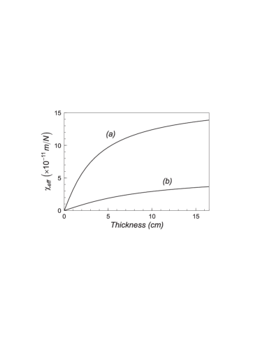
We have numerically computed the effective susceptibility for different thicknesses. Figure 2 shows the result obtained by computing 30 different values of the thickness. For each value, the curvature radius and the diameter of the mirror are determined according to eqs. (13) and (14). For example one gets cm and cm for a thickness of 7 cm. The two curves in figure 2 are obtained with different optical waists (2 cm for curve a and 5.5 cm for curve b). These waists correspond to the beam waists on the front and end mirrors of the VIRGO interferometer[10]. One observes a decrease of the thermal noise for a thinner mirror. This is partly due to the fact that the mechanical resonance frequencies are increased. It would be however difficult to use a very thin mirror since its diameter would become very large ( evolves as for small ).
If we consider a reasonable thickness of 7 cm, we obtain an effective susceptibility equal to m/N for an optical waist of 2 cm, and m/N for cm. These results can be compared to the values obtained for cylindrical mirrors, that is m/N ( cm) and m/N ( cm)[10]. The internal thermal noise of a plano-convex mirror is thus significantly smaller, by at least a factor 4. If the constraint on the diameter can be relaxed, even larger noise reduction may be obtained.
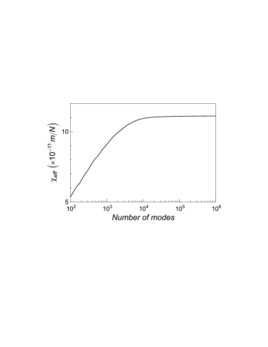
We have checked the validity of the numerical calculation by plotting the effective susceptibility as a function of the number of computed modes, for example in the case of a thickness of 7 cm and an optical waist of 2 cm (figure 3). This curve shows that results become valid as soon as the number of computed modes is larger than 104. Since the numerical calculation only deals with simple analytical expressions, it can easily be processed with a very large number of modes, such as 106.
III Relation with the optical mass
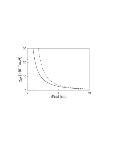
Figure 4 shows the variation of the effective susceptibility as a function of the optical waist. The thermal noise is reduced for a wider waist. The mirror displacement is actually averaged over the beam waist. Since the maximum displacement is at the center of the mirror, one gets less noise for a wide waist.
It is possible to derive a simple approximation of the thermal noise in the case of a thickness much smaller than the curvature radius . We can then assume that the transverse acoustic modes are degenerate and we can replace the resonance frequencies by the value for (eq. 17). The sum over in the effective susceptibility (eq. 12) is then a geometric sum and one gets a simple estimate of the susceptibility in terms of an optical mass given by[15]
| (20) | |||||
| (21) |
The effective susceptibility is thus equivalent to the one of a single harmonic oscillator of resonance frequency and of mass corresponding to the mass of the part of the mirror illuminated by the light beam (term in brackets in eq. 21). The resulting susceptibility is shown as a dashed curve in figure 4 and appears to be a good approximation of the computed susceptibility. It is actually an overestimation of the effective susceptibility since the resonance frequencies are always larger than .
This result shows that the internal thermal noise depends only on a few parameters, mainly the optical waist and the thickness . The effective susceptibility evolves as and one obtains a lower noise for a thin mirror and a wide optical waist, as shown in figures 2 and 4. We have ckecked that the thermal noise is quite insensitive to other parameters such as the curvature radius or the mass of the mirror. We have computed the effective susceptibility for different masses by varying the curvature radius while the thickness is kept constant. The relative variation of the thermal noise is less than 5% for masses between 5 kg and 50 kg.
Note that this relation with the optical mass seems to be a specific behavior of the plano-convex geometry. One can define an effective mass for a cylindrical mirror by a relation similar to (20) but this mass is no longer related to the optical mass. From the point of view of thermal noise, the comparison between cylindrical and plano-convex geometries shows that the effective mass of a cylindrical mirror is usually larger than the optical mass, whereas the fundamental resonance frequency is approximately 10 times larger for the plano-convex geometry (typically 40 kHz instead of 4 kHz). This drastic increase of the fundamental frequency explains why the plano-convex mirror is less noisy.
IV Misalignment of the light beam
We now study the effect of a misalignment of the light beam. Since the maximum thermal displacement is at the center of the mirror, moving the light beam off center must improve the noise. However, the number of modes () which contributes to the thermal noise rapidly increases with the misalignment. As a consequence there is only a slight effect for cylindrical mirrors[10]. In the case of a plano-convex mirror, acoustic modes are more confined around the center of the mirror and one expects a larger effect of misalignment.
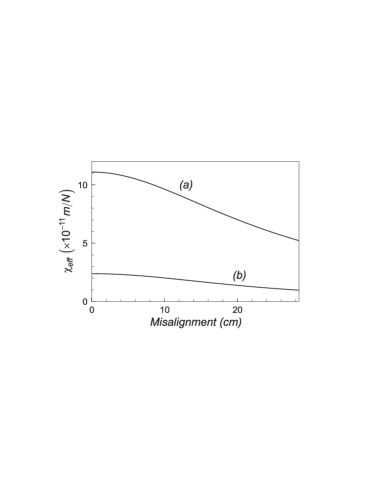
To efficiently compute the effective susceptibility, we replace the Laguerre polynomial in eq. (15) by two Hermite polynomials and we use the recurrence relations between them in the numerical calculation. The resulting susceptibility is shown in figure 5, for a 7-cm thick mirror and for an optical waist of 2 cm (curve a) and of 5.5 cm (curve b). The reduction of thermal noise with misalignment is clearly visible on those curves since a reduction factor on the order of 2 can be reached.
V Conclusion
We have studied the internal thermal noise at low frequency of a plano-convex mirror. We have shown that it can be related to the susceptibility of an equivalent pendulum of resonance frequency equal to the fundamental resonance frequency of the mirror and of mass equal to the optical mass. As a consequence the thermal noise mainly depends on the thickness of the mirror and on the waist of the light beam. We have found that a thin plano-convex mirror has a lower noise than a standard cylindrical mirror of same mass. For a 7-cm thickness, the thermal noise is approximately 10 times lower. Using such plano-convex mirrors in gravitational-wave interferometers would thus increase the sensitivity of the interferometer in the intermediate frequency domain.
The results derived in this paper are based on a paraxial approximation which allows to describe the acoustic modes of the mirror as Gaussian modes. This approximation is valid if the diameter and the curvature radius of the mirror are large as compared to its thickness and to the optical waist. Otherwise, high-order transverse modes may become sensitive to edge effects and they may be not adequately described as Gaussian modes. These modes however do not significantly contribute to the thermal noise since the overlap with light becomes small for high-order modes. Anyway, considering the large noise reduction that would be obtained by a simple change of the mirror shape, we believe that it would be of great interest to experimentally compare the background thermal noises of cylindrical and plano-convex mirrors, for example by using a high-sensitivity displacement sensor such as a high-finesse cavity[17].
Finally, let us note that we have studied a geometry with a sharp edge on the circumference. Since the acoustic modes are confined near the center of the mirror, it is possible to truncate the borders of the mirror in order to have an edge with a finite size. This would not degrade the thermal characteristics of the mirror, but it will change its diameter and its mass. A compromise must be found in practice between the thickness which determines the amplitude of internal noise, the mass which is important for suspension thermal noise, and the diameter of the mirror.
REFERENCES
- [1] P.R. Saulson, Phys. Rev. D 42, 2437 (1990)
- [2] C. Bradaschia et al., Nucl. Instrum. Meth. A 289, 518 (1990)
- [3] A. Abramovici et al., Science 256, 325 (1992)
- [4] G.I. Gonzalez, P.R. Saulson, J. Acoust. Soc. Am. 96, 207 (1994)
- [5] J.E. Logan, J. Hough, R.D. Thomson, Phys. Lett. A 218, 181 (1996)
- [6] J.E. Logan, N.A. Robertson, J. Hough, Phys. Lett. A 170, 352 (1992)
- [7] A. Gillespie, F. Raab, Phys. Lett. A 190, 213 (1994)
- [8] G.I. Gonzalez, P.R. Saulson, Phys. Lett. A 201, 12 (1995)
- [9] V.B. Braginsky, V.P. Mitrofanov, K.V. Tokmakov, Phys. Lett. A 218, 164 (1996)
- [10] F. Bondu, J.Y. Vinet, Phys. Lett. A 198, 74 (1995)
- [11] A. Gillespie, F. Raab, Phys. Rev. D 52, 577 (1995)
- [12] Y. Levin, Phys. Rev. D 57, 659 (1998)
- [13] F. Bondu, P. Hello, J.Y. Vinet, Phys. Lett. A 246, 227 (1998)
- [14] C.J. Wilson, J. Phys. D : Appl. Phys. 7, 2449 (1974)
- [15] M. Pinard, Y. Hadjar, A. Heidmann, Eur. Phys. J. D 7, 107 (1999)
- [16] H.W. Kogelnik, T. Li, Appl. Opt. 5, 1550 (1966)
- [17] Y. Hadjar, P.F. Cohadon, C.G. Aminoff, M. Pinard, A. Heidmann, Europhys. Lett. 47, 545 (1999)