The Faraday quantum clock and non-local photon pair correlations
Abstract
We study the use of the Faraday effect as a quantum clock for measuring traversal times of evanescent photons through magneto-refractive structures. The Faraday effect acts both as a phase-shifter and as a filter for circular polarizations. Only measurements based on the Faraday phase-shift properties are relevant to the traversal time measurements. The Faraday polarization filtering may cause the loss of non-local (Einstein-Podolsky-Rosen) two-photon correlations, but this loss can be avoided without sacrificing the clock accuracy. We show that a mechanism of destructive interference between consecutive paths is responsible for superluminal traversal times measured by the clock.
I Introduction
A quantum clock is an observable capable of measuring the time duration of a physical process in a quantum system[1, 2]. One of the major applications discussed in this context is the measurement of the traversal time of a quantum particle through a specific region in space[2, 3, 4, 5, 6]: it can be performed by applying a field in this region, thereby inducing the evolution of the particle’s internal states at a rate which is a known function of the field strength. If the field is weak enough, then its effect on the translational degrees of freedom of the particle is assumed to be negligible and the traversal time can then be deduced from the final internal state of the particle outside the region where the field takes effect.
The first quantum clock to be discussed was based on the Larmor spin precession of an electron in a magnetic field[3, 4]. By analogy, it was later proposed to use the Faraday polarization rotation of an electromagnetic wave in a birefringent crystal[5] or in a magneto-refractive medium[6] as a clock for photon traversal times in dielectric structures. For both Larmor precession and Faraday polarization rotation, the theoretical analysis led to the definition of a complex time variable[3, 4, 6]. In the case of the Larmor clock for electrons, its real and imaginary parts measure the spin rotation perpendicular and parallel to the field, respectively. In the case of the Faraday clock for photons, its real part measures the rotation of the main axis of polarization while its imaginary part measures the ellipticity of the resulting polarization.
The works surveyed above have left certain open questions of fundamental importance: (i) How do the measured values of traversal times depend on the clock precision? (ii) What is the origin of the differences between traversal times measured by quantum clocks through different measuring schemes and how can they become superluminal[8, 9]? (iii) Whereas field quantization is not required for analyzing the evanescent-wave traversal (tunneling) of electromagnetic wavepackets through dielectrics or the corresponding traversal times, are there nonclassical properties of evanescent photons, which are affected by the precision of their internal quantum clock? Our purpose here is to elucidate the above questions for the Faraday rotation clock.
In Section II we use our previously introduced explanation that evanescent-wave transmission or tunneling results from destructive interference of internal traversal paths[7], to show that the mere possibility of a time-measurement by an internal clock tends to affect this interference and thus increase the transmission. We demonstrate this fundamental result for the transmission of photons through a layered dielectric medium with Faraday rotation. In Section III we discuss different measuring schemes and their relevance to the traversal time problem. We show how superluminal traversal times measured by the clock are caused by strong destructive interference of traversal paths in the evanescent-wave (tunneling) regime. In Section IV we discuss the effect of the Faraday clock in a dielectric structure on two-photon correlations and show that correlations are not lost by the introduction of a Faraday clock, unless the filtering effect of the clock on circular polarizations is significant.
II Path Interference and the Faraday Clock Precision
The Faraday effect of polarization rotation in a magneto-refractive medium is caused by the fact that the left-hand () and right-hand () circular polarization components with respect to an applied magnetic field have different refractive indices and in the medium. The linear polarizations are superpositions of the two circular polarizations with equal amplitudes. While propagating a distance through the medium, the two circular polarization states of light at frequency acquire different phases . If the transmission amplitudes of the two circular polarization states are equal, then a linearly polarized photon entering the medium will exit with another linear polarization rotated by an angle with respect to the initial one. However, if the transmission amplitudes are different for the two circular polarizations, then the transmitted photon is elliptically polarized. In the extreme case where only one circular-polarization component is transmitted, the medium acts as a perfect filter for circular polarizations.
The use of the Faraday effect as a quantum clock is based on the fact that the phase difference between the two circular-polarization states is proportional to the optical length in the medium, where is the mean refractive index. If the transmission probabilities of the two circular-polarization states are equal, then the polarization rotation of an initially linearly polarized photon is proportional to the time it spent in the medium, namely
| (1) |
where is the mean velocity in the medium.
Here we discuss the transmission of a photon through a magneto-refractive periodic dielectric structure ("a photonic band-gap structure"). The structure is made of alternating dielectric layers and with dielectric constants and widths , so that the total width of the structure is . In the presence of a magnetic field each layer acquires different refractive indices for left- and right-circular polarizations. The Faraday effect can measure the traversal time through the structure if the ratio is kept constant for the two layers. The transmitted wave at is a superposition of many partial waves corresponding to different patterns of internal reflections between the layers. Each such pattern can be described as a path , traversing times the type 1 layers and times the type 2 layers, with a certain number of internal reflections between the layers, each having an amplitude . We can assume that in a weak magnetic field this inter-layer reflection amplitude is approximately the same for the two circular polarizations, and therefore the total amplitude of transmission along a certain path is equal for the two polarization states.
It follows from the discussion above, that the polarization state of an initially linearly polarized photon traversing a certain path in the dielectric structure remains linear and is rotated by an angle , where () and , as illustrated in Fig. 1. The state of the transmitted photon at is given by the superposition
| (2) |
where is the sum over amplitudes for transmission through paths , which traverse the two different dielectric layers and times and . The state with , is the linear polarization state
| (3) |

A simpler form of the photon states is obtained by using the circular polarization basis. If the incident photon is in the state , then the transmitted photon state is
| (4) |
where is the spectral transmission function for a monochromatic wave with frequency .
Since the two parts of the wavefunction in Eq. (4) are distinguishable by a circular polarizer, there is no interference between them and the total probability of the photon to be transmitted can be written as an average of the transmission probabilities of photons incident on a non-gyrotropic barrier at frequencies
| (5) |
where . This loss of interference leads to the enhancement of transmission probability in frequency bands where the transmission is low. In order to demonstrate this point, notice that if is small compared to the scale of variation of , then we obtain from Eq. (5)
In frequency bands where the transmission is low, especially in the tunneling (evanescent) regime, the curvature is positive. We therefore find that the presence of the clock raises the transmission probability (as compared to the same probability in the absence of a clock), because the destructive interference of traversal paths is progressively washed out as increases.
III Time measurements by the Faraday Clock: Superluminality as Path Interference
What kind of measurement has to be performed in order to obtain a meaningful traversal time through the dielectric structure in Fig. 1? If we were able to single out only transmitted photons that leave the structure in the exact state , then we could know what group of paths those photons went through and determine the exact traversal time through the dielectric structure. However, since the space of polarization states is spanned by only two orthogonal basis states, we are limited to the analysis of their detection probabilities rather than the determination of their state. In what follows we consider several alternative measuring schemes and discuss their relevance to the traversal time problem:
A. The first alternative is to measure the number of transmitted photons with linear polarization orthogonal to the initial polarization direction and compare it to the total number of transmitted photons. The traversal time can be defined by assuming that the polarization state of the photon after a time is given by . This implies that
| (6) |
We then find
| (7) |
In the limit this becomes
| (8) |
where is the phase of the transmission function . The variable is well known in the context of electron tunneling through potential barriers as "the Büttiker-Landauer time"[3, 10].
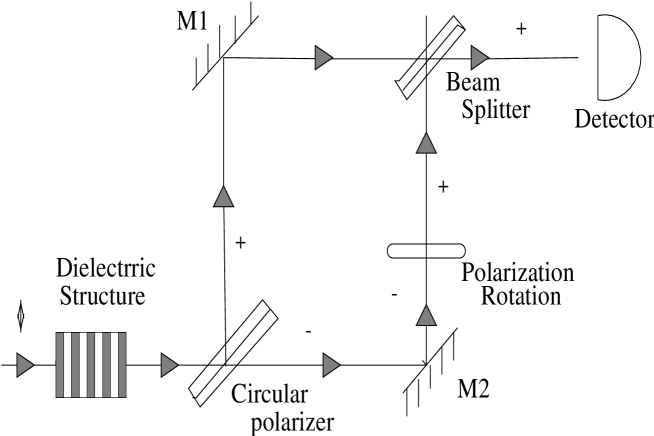
B. The second alternative is to make a direct measurement of the phase difference between the two circular polarization components of the transmitted photons. This can be done by using a circular polarizer to separate the two components of the transmitted photons and then join them again by a beam-splitter as shown in Figure 2. If the optical length of one arm of this interferometer with respect to the other is adjustable, then the detection rate at one port of the beam-splitter as a function of the length difference between the arms satisfy the proportionality relation
| (9) |
where is an additional phase difference introduced by the optical components. The phase difference between the two polarization components is then given by , where is the value of which maximizes . The traversal time in the dielectric structure can then be extracted as
| (10) |
which is the well-known value obtained in wavepacket measurements.
C. The third alternative is to scan the rotation angles of polarization from to by a linear polarizer, and define the peak rotation angle as the polarizer angle where the maximal number of counts is obtained. The counting probability for a polarizer at angle is given by
| (11) |
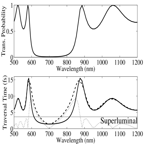
where . The maximal value of this function is obtained at , which corresponds to the same phase-time as given in Eq. (10). In a periodically-layered dielectric structure, the evanescent-wave transmission probability is nearly symmetric with respect to the center of the forbidden band gap (Fig. 3(a)) and so are the traversal times (8) and (10) (Fig. 3(b)). Hence, if is at the band-gap center.
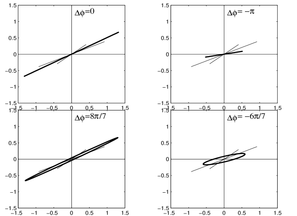
In Ref. REFERENCES we have shown that low transmission of a wavepacket together with abnormally short wavepacket peak traversal time is a consequence of destructive interference between consecutive partial transmitted wavepackets. In order to demonstrate the effects of interference on the clock read-out, we analyze the polarization state formed by a superposition of two linear polarization states that appear in Eq. (4). Consider the polarization state
| (12) |
where is the amplitude of the th transmitted wave. As demonstrated in Figure 4, if and , it can be shown that if the interference between the terms and is predominantly destructive, i.e., when , then the main axis of polarization of the resulting elliptic polarization state has an angle . In particular, if the phase difference between and is exactly , such that , then the resulting state has linear polarization
and whenever .
In general, the main axis of the elliptic polarization state of the transmitted photons is given by the maximum overlap with a linear polarization state . Using Eq. (2), we can express the probability function in Eq. (11) as
| (13) |
In order to obtain the value of we find the maximum of by equating its derivative to zero. We then obtain the following angle of the main axis of polarization
If is very small, then and . The clock time then reads exactly the same as the mean wavepacket traversal time[7]. Hence, destructive interference between different terms gives rise to predominantly negative contributions , which cause the effect of abnormally short or even superluminal clock read-out times.
IV Faraday Clock Effect in Nonlocal (EPR) Photon Correlations
Here we consider measurements that have never been discussed before, which pertain to non-local (Einstein-Podolsky-Rosen) correlations between entangled photons. Suppose that we repeat the Aspect experiment[11] using a correlated pair of photons, but insert a Faraday-rotating reflective structure (of the kind depicted in Fig. (1)) in the way of one of the photons (Figure 5). If the correlations between the transmitted photon and its twin are reduced, then the violation of Bell’s inequality is expected to be weakened. To what extent does the Faraday clock affect the violation of the inequality?

Let us take the initial state of the field to be
| (15) | |||||
where the first entry in the ket-vector refers to the state of the photon transmitted through the Faraday-rotating structure and travelling to detector 1 and the second entry refers to the state of the photon travelling to detector 2.
Bell’s inequality in the formulation of Clauser-Horne-Shimony-Holt (CHSH) makes use of the correlation function[12]
| (16) |
where is the measured intensity, the superscripts refer to intensity measured at detectors 1 and 2 and the signs refer to measurements with polarizer set at angles and ().
Since detector 1 measures only the fraction of photons transmitted through the Faraday-rotating structure, the state of the photons near the detectors is given by . We then find
| (18) | |||||
| (19) |
where , and similarly for the other correlations. The correlation function in Eq. (16) becomes
| (20) |
The CHSH inequality for measurements at polarizer angles is
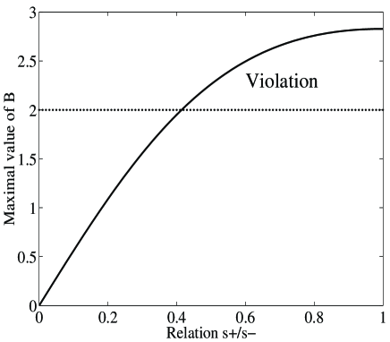
Without a Faraday rotating reflective structure we would have had but with a barrier the cosine term is shifted by a certain phase and multiplied by a factor which is always smaller or equal to unity (Fig. 6). This factor is maximal when , namely, when the right- and the left-circular polarizations are not separated. This happens if is either very small (weak clock) or when lies at a symmetry point (extremum) of the curve, e.g., if lies in the center of the band gap of the structure (Fig. 3(a)). By contrast, if the two polarizations are not equivalent, is reduced and the violation of the inequality is diminished, indicating partial loss of the two-photon correlations. This loss of correlation is explained by the fact that the Faraday-rotating structure acts as a filter for certain polarizations and thus the transmitted photons measured at detector 1 are a sub-ensemble of the original photons, which does not represent the polarization state of the initial photon population. When is small, it is easy to show from Eq. (20) that the maximal value of becomes
| (21) |
where
| (22) |
The variable measures the effectiveness of the Faraday-rotating structure as a circular polarizer. It measures the ability of the structure to separate between left- and right-circularly polarized photons. Although having units of time, it is difficult to refer to any meaning connected with time duration. However, it is possible to treat as a typical frequency scale over which the transmissivity of the dielectric barrier is significantly changed.
V Summary
We have analysed in this paper the transmission of photons through a layered dielectrtic medium with Faraday rotation and have sketched measurements of their traversal times in order to elucidate possible quantum clock mechanisms in the evanescent-wave (tunneling) regime. For the first time, both single-photon and two-photon (quantum electrodynamical) properties have been considered in this context.
Destructive interference between different traversal paths has been shown to be the origin of the effect of abnormally short or even superluminal clock read-out times. Several possible schemes have been proposed for traversal-time measurements based on the Faraday-clock phase shifts.
In frequency bands where the transmission is low, especially in the tunneling (evanescent-wave) regime, we have shown that the presence of the clock tends to wash out the destructive interference and thereby raise the transmission probability as compared to its counterpart in the absence of a clock.
Perhaps the most intriguing subject considered here are measurements of non-local correlations between two entangled photons with a Faraday-rotation structure in the way of one of the photons. The two-photon correlation function , which is used to calculate the violation of Bell’s inequality, is shifted by a phase and multiplied by a factor which is always smaller or equal to unity (Figure 6), as a result of the Faraday rotation. This factor is maximal when the right and left circular polarizations are not separated. This happens if the Faraday-clock rate is either very small or if the photon frequency lies at a symmetry point (extremum) of the transmission curve, e.g., if lies at the center of a band gap. The latter result is remarkable, since it allows us to measure two-photon entanglement (Bell’s inequality violation) without sacrificing the Faraday clock accuracy. By contrast, if the two polarizations are not equivalent, is reduced and the violation of the inequality is diminished, indicating partial loss of the two-photon correlations. This loss of correlation is explained by the fact that the Faraday-rotating structure acts as a filter for certain polarizations and thus the transmitted photons measured at detector 1 are a sub-ensemble of the original photons, which does not represent the polarization state of the initial photon population.
∗ Present address: Clarendon Laboratory, Department of Physics, University of Oxford, Oxford, UK OX1 3PU
VI Acknowledgments
This work has been supported by Minerva, ISF and EU (TMR) grants.
REFERENCES
- [1] Asher Peres, Am. J. Phys. 48, 552 (1980)
- [2] A. J. Baz’ , Sov. J. Nucl. Phys. 4, 182, 5, 1651 (1967)
- [3] M. Büttiker and R. Landauer, Phys. Rev. Lett. 49, 1739 (1982). Physica Scripta, Vol. 32, 429 (1985)
- [4] B. Sokolovski and L. M. Baskin, Phys. Rev. A 36, 4604 (1987)
- [5] M. Deutsch and J. E. Golub, Phys. Rev. A 53, 434 (1995); Y. Japha and G. Kurizki, Ann. Israel Physical Society, Vol. 12 (1995); Y. Japha and G. Kurizki, in The Dilemma of EPR - 60 years later, eds. A. Mann and M. Revzen (IOP, Bristol, 1996).
- [6] V. Gasparian, M Ortuno, J. Ruiz and E Cuevas, Phys. Rev. Lett. 75, 2312 (1995)
- [7] Y. Japha and G. Kurizki, Phys. Rev. A 53, 586 (1996); Phys. Rev. Lett. 77, 2909 (1996).
- [8] A. M. Steinberg, P. G. Kwiat and R. Y. Chiao, Phys. Rev. Lett. 71, 708 (1993); Sci. Am. 269 (2), 52 (1993).
- [9] Ch. Spielmann, R. Szipöcs, A. Stingl and F. Krausz, Phys. Rev. Lett. 73, 2308 (1994)
- [10] E. H. Hauge and J. A. Stovneng, Rev. Mod. Phys. 61, 917 (1989)
- [11] A. Aspect, P. Grangier, G. Roger, Phys. Rev. Lett. 49, 91 (1982), A. Aspect, J. Dalibard, G. Roger, Phys. Rev. Lett. 49,1804 (1982)
- [12] D. F. Walls, G. J. Milburn, Quantum Optics, Springer Verlag (Berlin-Heidelberg, 1994), p. 262-278; M. Scully and M. S. Zubairy, Quantum Optics (Cambridge University Press, 1997)