Cooling of a mirror by radiation pressure
Abstract
We describe an experiment in which a mirror is cooled by the radiation
pressure of light. A high-finesse optical cavity with a mirror coated on a
mechanical resonator is used as an optomechanical sensor of the Brownian
motion of the mirror. A feedback mechanism controls this motion via the
radiation pressure of a laser beam reflected on the mirror. We have
observed either a cooling or a heating of the mirror, depending on the gain
of the feedback loop.
PACS : 42.50.Lc, 04.80.Nn, 05.40.Jc
Thermal noise is a basic limit for many very sensitive optical measurements such as interferometric gravitational-wave detection[1, 2, 3]. Brownian motion of suspended mirrors can be decomposed into suspension and internal thermal noises. The latter is due to thermally induced deformations of the mirror surface and constitutes the major limitation of gravitational-wave detectors in the intermediate frequency domain[4, 5]. Observation and control of this noise have thus become an important issue in precision measurements[6, 7, 8]. In order to reduce thermal noise effects, it is not always possible to lower the temperature and other techniques have been proposed such as feedback control[9].
In this letter we report the first experimental observation of the cooling of a mirror by feedback control. The principle of the experiment is to detect the Brownian motion of the mirror with an optomechanical sensor and then to freeze the motion by applying an electronically controlled radiation pressure on the mirror. Mechanical effects of light on macroscopic objects have already been observed, such as the dissipative effects of electromagnetic radiation[10], the optical bistability and mirror confinement in a cavity induced by radiation pressure[11], or the regulation of the mechanical response of a microcantilever by feedback via the photothermal force[12]. In our experiment the radiation pressure is driven by the feedback loop in such a way that a viscous force is applied to the mirror. It thus plays a role somewhat similar to the one in optical molasses for atoms.
The cooling mechanism can be understood from the experimental setup shown in figure 1. The mirror is used as the rear mirror of a single-ended Fabry-Perot cavity. The phase of the field reflected by the cavity is very sensitive to changes in the cavity length[13, 14, 15]. For a resonant cavity, a displacement of the rear mirror induces a phase shift of the reflected field on the order of
| (1) |
where is the cavity finesse and is the optical wavelength. This signal is superimposed to the quantum phase noise of the reflected beam. Provided that the cavity finesse is high enough, this quantum noise is negligible and the Brownian motion of the mirror can be detected by measuring the phase of the reflected field[15].
To cool the mirror we use an auxiliary laser beam reflected from the back on the mirror. This beam is intensity-modulated by an acousto-optic modulator driven by the feedback loop so that a modulated radiation pressure is applied to the mirror. The resulting motion can be described by its Fourier transform at frequency which is proportional to the applied forces
| (2) |
where is the mechanical susceptibility of the mirror. If we assume that the mechanical response is harmonic, this susceptibility has a lorentzian shape
| (3) |
characterized by a mass , a resonance frequency and a damping related to the quality factor of the mechanical resonance by .
The force in eq. (2) is a Langevin force responsible for the Brownian motion of the mirror. At thermal equilibrium its spectrum is related to the mechanical susceptibility by the fluctuation-dissipation theorem
| (4) |
where is the temperature. The resulting thermal noise spectrum of the mirror motion has a lorentzian shape centered at frequency and of width .
The second force in eq. (2) is the radiation pressure exerted by the auxiliary laser beam and modulated by the feedback loop. Neglecting the quantum phase noise in the control signal, this force is proportional to the displacement of the mirror (eq. 1). We choose the feedback gain in such a way that the radiation pressure is proportional to the speed of the mirror
| (5) |
where is related to the electronic gain. The radiation pressure exerted by the auxiliary laser beam thus corresponds to an additional viscous force for the mirror. The resulting motion is given by
| (6) |
This equation is similar to the one obtained without feedback (eq. 2 with ) except that the radiation pressure changes the damping without adding any fluctuations. The noise spectrum of the mirror motion still has a lorentzian shape but with a different width and a different height. The variation of height can be characterized by the amplitude noise reduction at resonance frequency
| (7) |
The resulting motion is then equivalent to a thermal equilibrium at a different temperature which can be either reduced or increased depending on the sign of the gain
| (8) |

We now describe our experiment. The mirror is coated on the plane side of a small plano-convex mechanical resonator made of silica (figure 1). The coating has been made at the Institut de Physique Nucléaire de Lyon on a 1.5-mm thick substrate with a diameter of 14 mm and a curvature radius of the convex side of 100 mm. Internal acoustic modes correspond to gaussian modes confined around the central axis of the resonator[16, 17]. The fundamental mode studied in this paper is a compression mode with a waist equal to 3.4 mm and a resonance frequency close to 2 MHz[15, 17]. The front mirror of the cavity is a Newport high-finesse SuperMirror (curvature radius = 1 m, transmission = 50 ppm) held at 1 mm from the back mirror. We have measured the following parameters of the cavity : free spectral range = 141 GHz, cavity bandwidth = 1.9 MHz, beam waist = 90 m. These values correspond to a finesse of 37000.
The light entering the cavity is provided by a titane-sapphire laser working at 810 nm and frequency-locked to a stable external cavity which is locked to a resonance of the high-finesse cavity by monitoring the residual light transmitted by the rear mirror. The beam is intensity-stabilized and spatially filtered by a mode cleaner. One gets a 100-W incident beam on the high-finesse cavity with a mode matching of 98%. The phase of the field reflected by the cavity is measured by homodyne detection. The reflected field is mixed with a 10-mW local oscillator and a servoloop monitors the length of the local oscillator arm so that we measure the phase fluctuations of the reflected field. This signal is sent both to the feedback loop and to a spectrum analyzer.
The feedback loop consists of an amplifier with variable gain and phase which drives the acousto-optic modulator. The 500-mW auxiliary beam is uncoupled from the high-finesse cavity by a frequency shift of the acousto-optic modulator (200 MHz) and by a tilt angle of 10∘ with respect to the cavity axis. We have checked that this beam has no spurious effect on the homodyne detection. A band-pass filter centered at the fundamental resonance frequency of the mirror is also inserted in the feedback loop to reduce its saturation. For large gains, the radiation pressure can become of the same order as the Langevin force and it must be restricted in frequency in order to get a finite variance. The electronic filter has a quality factor of 200 and limits the efficiency of the feedback loop to a bandwidth of 9 kHz around the fundamental resonance frequency.
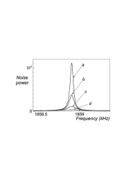
Figure 2 shows the phase noise spectrum of the reflected field obtained by an average of 1000 scans of the spectrum analyzer with a resolution bandwidth of 10 Hz. Curve (a) is obtained at room temperature without feedback. It reproduces the thermal noise spectrum of the mirror which is concentrated around the fundamental resonance frequency (1858.9 kHz) with a width of 45 Hz (mechanical quality factor ). The spectrum is normalized to the shot-noise level and it clearly appears that the thermal noise is much larger than the quantum phase noise[15].
Curves (b) to (d) are obtained with feedback for increasing electronic gains. The phase of the amplifier is adjusted to maximize the correction at resonance. From eqs. (5) and (6) this corresponds to a global imaginary gain for the loop and to a purely viscous radiation pressure force. The control of the mirror motion is clearly visible on those curves. The thermal peak is strongly reduced while its width is increased. The amplitude noise reduction at resonance is larger than 20 for large gains.
The effective temperature can be deduced from the variance of the mirror motion which is equal to the integral of the spectrum . From eqs. (4), (6) and (8) one gets the usual relation for a harmonic oscillator at thermal equilibrium
| (9) |
The decrease of the area of the thermal peak observed in figure 2 thus corresponds to a cooling of the mirror.
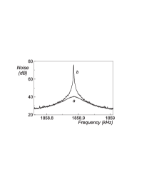
Figure 3 shows the effect of feedback for a reverse gain (). Noise spectra are obtained by an average of 500 scans with a resolution bandwidth of 1 Hz. Curve (b) exhibits a strong increase of the thermal peak which now corresponds to a heating of the mirror. The feedback also reduces the damping from to , thus increasing the quality factor of the resonance. We have obtained a maximum effective quality factor of (), limited by the saturation of the feedback loop.
It is instructive to study the efficiency of the cooling or heating mechanism with respect to the gain of the feedback loop. Figure 4 shows the variation of the damping , of the amplitude noise reduction at resonance and of the cooling factor , as a function of the feedback gain. These parameters are derived from the experimental spectra by lorentzian fits which give the width and the area of the thermal peak, the latter being related to the effective temperature by eq. (9). To measure the feedback gain, we detect the intensity of the auxiliary beam after reflection on the mirror. The ratio between the modulation spectrum of this intensity at frequency and the noise spectrum is proportional to the gain . This measurement takes into account any nonlinearity of the gain due to a possible saturation of the acousto-optic modulator.
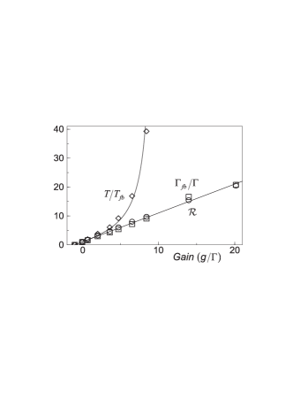
As expected from eqs. (6) and (7), the damping and the amplitude noise reduction have a linear dependence with the gain, as well for cooling () as for heating (). The straight line in figure 4 is in excellent agreement with experimental data and allows to normalize the gain to the damping , as this has been done in the figure.
This figure also shows that large cooling factors can be obtained. This cooling factor does not however evolve linearly with the gain as it would be expected from eq. (8). This is due to the presence of a background thermal noise visible in figure 2. This noise is related to all other acoustic modes of the mirror and to the thermal noise of the coupling mirror of the cavity. The feedback loop has not the same effect on this noise and on the fundamental thermal peak. The solid curve in figure 4 corresponds to a theoretical model in which the background noise is assumed to be unchanged by the feedback. As a consequence, only the fondamental mode is cooled at a temperature whereas all other modes stay in thermal equilibrium at the initial temperature . The resulting cooling factor is in excellent agreement with experimental data.
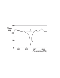
The cooling mechanism is not limited to the mechanical resonance frequencies. Figure 5 shows the cooling obtained at frequencies well below the fundamental resonance frequency. The electronic filter is now centered around 800 kHz and the feedback loop reduces the background thermal noise (curve a). The width of the noise reduction (curve b) is related to the filter bandwidth. The phase and the gain of the feedback loop has been adjusted since the electronic gain has now to be compared to the real part of the inverse of the mechanical susceptibility at low frequency (eq. 6). Note that the amplitude of the radiation pressure exerted by the auxiliary laser beam is however approximately the same as in the resonant case. Large noise reduction is actually obtained when the radiation pressure is on the order of the Langevin force whose amplitude is independent of frequency (eq. 2).

In conclusion, we have observed a thermal noise reduction by a factor 20 near the fundamental resonance frequency. The radiation pressure exerted by the feedback loop corresponds to a viscous force which increases the damping of the mirror without adding thermal fluctuations. For large gains, the thermal peak of the fundamental mode becomes of the same order as the background thermal noise and no global thermal equilibrium is reached. As far as an effective temperature can be defined for the fundamental mode, we have obtained a reduction of this temperature by a factor 40. We have also observed a heating of the mirror for reverse feedback gains, and a cooling of the background thermal noise at low frequencies.
The cooling mechanism demonstrated in this paper may be useful to increase the sensitivity of gravitational-wave interferometers. The main difficulty is to freeze the thermal noise without changing the effect of the signal. We propose in figure 6 a possible scheme to control the thermal noise of one mirror of the interferometer. A cavity performs a local measurement of the mirror motion which is fed back to the mirror via the radiation pressure of a laser beam. The coupling mirror of the cavity is a small plano-convex mirror with a high mechanical resonance frequency and a low background thermal noise at low frequency. As a consequence the cavity measures the thermal noise of the mirror of the interferometer. For a short cavity, this measurement is not sensitive to a gravitational wave and the cooling can reduce the background thermal noise at the gravitational-wave frequencies without changing the response of the interferometer.
REFERENCES
- [1] P.R. Saulson, Phys. Rev. D 42, 2437 (1990)
- [2] C. Bradaschia et al., Nucl. Instrum. Meth. A 289, 518 (1990)
- [3] A. Abramovici et al., Science 256, 325 (1992)
- [4] F. Bondu, J.Y. Vinet, Phys. Lett. A 198, 74 (1995)
- [5] A. Gillespie, F. Raab, Phys. Rev. D 52, 577 (1995)
- [6] V.B. Braginsky, M.L. Gorodetsky, V.S. Ilchenko, S.P. Vyatchanin, Phys. Lett. A 179, 244 (1993)
- [7] M. Bernardini et al., Phys. Lett. A 243, 187 (1998)
- [8] D. Rugar, P. Grütter, Phys. Rev. Lett. 67, 699 (1991)
- [9] S. Mancini, D. Vitali, P. Tombesi, Phys. Rev. Lett. 80, 688 (1998)
- [10] V.B. Braginski, A.B. Manukin, M.Yu. Tikhonov, Zh. Eksp. Teor. Fiz. 58, 1549 (1970) [Sov. Phys. JETP 31, 829 (1970)]
- [11] A. Dorsel, J.D. McCullen, P. Meystre, E. Vignes, H. Walther, Phys. Rev. Lett. 51, 1550 (1983)
- [12] J. Mertz, O. Marti, J. Mlynek, Appl. Phys. Lett. 62, 2344 (1993)
- [13] N. Mio, K. Tsubono, Appl. Opt. 34, 186 (1995)
- [14] I. Tittonen et al., Phys. Rev. A 59, 1038 (1999)
- [15] Y. Hadjar, P.F. Cohadon, C.G. Aminoff, M. Pinard, A. Heidmann, quant-ph/9901056
- [16] C.J. Wilson, J. Phys. D : Appl. Phys. 7, 2449 (1974)
- [17] M. Pinard, Y. Hadjar, A. Heidmann, quant-ph/9901057, to be published in Eur. Phys. J. D