Error free quantum communication through noisy channels
Abstract
We suggest a method to perform a quantum logic gate between distant qubits by off-resonant field-atom dispersive interactions. The scheme we present is shown to work ideally even in the presence of errors in the photon channels used for communication. The stability against errors arises from the paradoxical situation that the transmitted photons carry no information about the state of the qubits. In contrast to a previous proposal for ideal communication [Phys. Rev. Lett. 78, 4293 (1997)] our proposal only involves single atoms in the sending and receiving devices.
PACS: 03.67.Hk, 42.50.-p, 03.65.-w, 03.67.-a
I introduction
Quantum mechanics is known to produce a variety of phenomena in lack of classical interpretation. In recent years the fields of quantum computation and quantum communication have tried to exploit these phenomena to propose computers and communication devices which are superior to their classical counterparts. One particular example is quantum teleportation which is based on the nonlocal features of the EPR-paradox. Quantum teleportation is transmission of qubits without actually sending the physical system, e.g. transfer of the state of an atom to another atom at a different location. Classically teleportation can be performed by measuring the state of an object and sending the information to the receiver who reconstructs the state in a similar object. In the quantum world it is not that easy. Quantum mechanics forbids us to gain exact knowledge of the state of an object. However, Bennett et al. have suggested that it is still possible to perform teleportation[1], provided that the transmitting system does not retain any information about the state which is transmitted. Recently quantum teleportation of a photonic state has been achieved experimentally [2, 3].
In practical realizations of teleportation the system may be subject to noise in the transmission channels. Recently, van Enk et. al. have shown that the effect of the noise can be completely avoided, if we make suitable physical assumptions about the noise in the channels [4].
Eliminating noise on quantum information is considerably more complicated than eliminating noise on classical information because quantum mechanics forbids copying of information , where is the state of a qubit ()[5]. However, quantum mechanics does allow what we shall call a backup copy , where a single quantum system is transfered to a state with projections on two different subspaces and , which are both equivalent to the initial state. (We use unnormalised states except where otherwise stated). We call it backup copying because if one half is “lost” (projected out), say the part, we may still have the intact quantum state in the part. (The exact meaning of this statement will become clear below).
In this paper we use the backup encoding to perform quantum communication in the presence of errors in the channel used for communication. Rather than considering teleportation as discussed by van Enk et. al., we perform a perfect control-not operation, which is slightly more general than teleportation. To perform the operation we use off-resonant dispersive interactions between atoms and the transmitted photons. We assume that all errors are due to imperfections in the transmission between atoms and and imperfections in the dispersive interaction, whereas measurements and unitary evolutions on a single atom are assumed ideal. With this assumption we show that our scheme works ideally even in the presence of a quite general class of errors.
We emphasize that our scheme is not a conventional quantum error correcting code [6]. We use a specific physical model of the noise to remove errors to all orders with a limited number of qubits whereas conventional error codes introduce new qubits to correct errors up to a certain order.
II General description
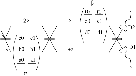
The control-not gate works between two atoms or ions. The control atom is called and the target is called . Here and are two three level atoms, where each level has a two fold Zeeman degeneracy (). The states of are denoted by , and and the states of are called , and , where and 1 represents the azimuthal quantum numbers and , see figure 1. In practice, one may have recourse to systems with a different arrangement of states, but our procedures are most easily explained in the suggested realization.
If we consider the quantum information to be stored in the two Zeeman degenerate ground state levels, the action of the control-not operation can be characterized by its action on suitable basis vectors for the atomic ground state
| (1) |
The control-not operation interchanges the states and of if and only if is in the state . A comment on notation: Rather than considering the evolution of a superposition of the four basis vectors (), we consider the evolution of each basis vector. This emphasizes that each vector in Eq. 1 could be entangled with other qubits as in a computational task.
Our scheme consists of local encodings and two transmissions of photons from to . We begin with a local backup encoding on . We then perform the first transmission followed by a symmetrization on and protection of relevant states of . Another transmission is performed and finally we extract the desired quantum states.
The effect of the transmissions is to entangle the levels of the two atoms. By performing local operations we can then use this entanglement to implement the control-not operation.
The stability of our scheme arises from the horizontal symmetry among the atomic states in figure 1. In the transmission we only use linearly () polarized pulses which couple states vertically. This means that the photons contain no information about whether is in 0 or 1. The photons only contain information about the levels of . If, for instance, we start with a superposition and a photon is absorbed during a transmission, the wavefunction will collapse to some energy level (for instance ), but our quantum mechanical superposition between 0 and 1 will be intact (). From this “backup” state we can start the transmission again and continue until we are successful.
We first describe the evolution in the ideal situation where we have perfect error free transmissions.
III Backup control-not under ideal conditions
To perform the evolution described by Eq. 1 we suggest using an experimental setup as shown in figure 1. Our setup can be divided into a sending section, a receiving section and the channels connecting them. The sending section consist of a beam splitter, the atom and another beam splitter. The receiving part is the atom , a beam splitter and two photon detectors. All beam splitters are 50/50. The channels are the two photon lines connecting the two sections. In a realistic implementation it might be preferable to use a delay rather than two distinct channels, but for the sake of clarity we apply two lines in our analysis.
Initially the qubits are stored in the ground states and . We first perform a local backup encoding on . With a linear pulse we take to .
We then perform the first photon transmission. A single linearly polarized photon is split into two orthogonal states and by a beam splitter. The field state interacts non-resonantly with the atom coupling the level with a detuning and a coupling constant g to a higher lying state in the atom. The energy shift of the level can be calculated in second order perturbation theory to be . If we choose an interaction time the phase of the state vector will change by if is in the level . A phase change of may not be realistic in an experiment, and we shall relax this assumption later.
We then recombine the two photon amplitudes yielding the two states and .
The receiving atom is prepared with a linearly polarized pulse so that is taken to . The photon state now couples non-resonantly to a higher level yielding a conditional phase shift of as described for atom , and we then apply a second pulse so that if the field is in the state will be taken back to by the last pulse, but if the field is in the state will be taken to due to the phase change induced by the field. Since the and states correspond to being in and respectively, this will create the desired entanglement between and , but at this point the atoms are also entangled with the photon.
We get rid of the photon with a quantum eraser: The two photon states and interfere yielding the two detector states and . We assume here that the mirrors are aligned so that corresponds to the incoming state [7]. We then perform a measurement revealing whether the photon is in or . If is measured we change the sign of the level to compensate a sign induced by the eraser.
A simple analysis shows that the transmission performs the operation
| (2) | |||
| (3) |
During transmission the Zeeman degeneracy plays no role. Subscripts i and j denoting the Zeeman state have only been written for later convenience.
Had we included the evolution of the level , the transmission would be a control-not between the levels ,, and , but this control- not will be vulnerable to errors. Our backup scheme makes it possible to perform a perfect control-not between the states , , and , also in the presence of errors. Paradoxically this may be achieved by means of the transmission described by Eq. 3 and local operations, even though the transmitted photons carry no information on the azimuthal quantum numbers.
Including the preparation of the evolution so far is given by
| (4) |
Now, the states are moved to storage states and the states and are interchanged by linearly polarized -pulses. A second photon is transmitted, causing again the evolution in Eq. 3. Since the -states of are not coupled to the incident photon, these states are not affected by the second transmission, and we end up with
| (5) |
The main result of this paper is that we are able to construct these states even in the presence of errors. This will be shown in sec. V. Within the quantum states in Eq. 5 we break the horizontal symmetry of azimuthal states 0 and 1 and extract the desired states on the right side of Eq. 1 by local operations.
We measure if is in the subspace spanned by and . This can for instance be done by interchanging and and making a QND measurement [8] of the energy of . If is found in the subspace spanned by and we interchange the amplitudes on and . If it is not we interchange the amplitudes on and . We then measure if is in the subspace spanned by and . This can be done with a pulse followed by a QND measurement of the atomic energy. From the results of these measurements one can construct a sequence of pulses which takes us to the desired states.
As a specific example of the extraction procedure consider the situation where is found in the subspace spanned by and . The measurement collapses Eq. 5 to this subspace and we apply a pulse which interchanges and
| (6) |
Now consider the situation where we measure that is in the subspace spanned by and . Since can be written and can be written this is seen to introduce a minus on the first two lines in Eq. 6. By subsequently transferring to and to we arrive in the desired states.
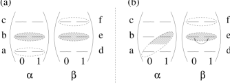
This extraction procedure is illustrated in figure 2. We recall that the qubits are represented as superpositions of the azimuthal quantum states and . Entanglement between the atoms is visualized by shading: Part (a) of the figure illustrates the states in Eq. 5, where is in the level () if is in (). Our first measurement chooses states in diagonally (part (b) in the figure and Eq. 6). Now, we interchange azimuthal states and of if is in . From the shading in the figure this is seen to correspond to interchanging and ( and if the other diagonal had been measured). Finally, all states are taken to the lowest level as described in the example after Eq. 6 and we end up in the desired states.
IV Error analysis
In this section we analyse the effect of errors and in the next section we show how our backup scheme eliminates these errors. We will assume that measurements and unitary evolutions in single atoms are perfect. All errors will be due to imperfections in the dispersive interactions and in the channels used for communication.
A Errors due to loss of photons
A photon is considered lost if it is not detected at the photon detectors in the end. Since the photons carry no information on the azimuthal quantum number the superposition between and states will not be disturbed. Using a QND measurement it can be detected whether is in or and the qubit will still be present horizontally. Similarly we can measure the energy of without disturbing the qubit and the initial states can be restored. We can then start over again and proceed with the transmission until it is successful.
B Errors without loss of photons
Phase shift in the dispersive interaction with We no longer assume that our dispersive interaction causes a phase shift which is . With a general phase shift the two levels and no longer give two orthogonal photon states ( and ) which can be separated by a beam splitter. But we can arrange our beam splitter so that always produces a photon in the channel. The atom in level , however, will yield a superposition of and
| (7) | |||||
| (8) |
We show in section V that our scheme still works because the erroneous component can be projected out with a measurement.
Errors in the channels. With the assumption that the photons cannot jump from one channel to the other and cannot be created in the channels, the most general evolution will be described by
| (9) | |||||
| (10) |
where the notation means that the wavepacket is changed in some way (change of shape and duration of the wavepacket etc.). The states and are assumed normalized. This evolution can be described by the non hermitian Hamiltonian of Monte Carlo wavefunctions [9] in the no jump stages of evolution.
We assume that the photon in two subsequent transmissions couples to independent and identical environments. With this assumption the evolution in Eq. 10 will be the same in the two transmissions provided that the photon is not lost. This assumption is further justified in [4].
Errors in the interaction with . The photon state does not interact with the atom and we assume that local laser pulses on are error free. This photon state will therefore not cause any transition in . The interaction between and is modified due to the imperfect dispersive interaction and the modified photon state. This means that may not be transfered to the level as desired. The effect of the interaction may be summarized as follows
| (11) | |||||
| (12) |
Errors in the photon detection. The two orthogonal states and are measured in an orthogonal basis {, }. The beam splitter is a 50-50 beam splitter and any overall phase factors may be absorbed in the definition of and . We can therefore write
| (13) | |||||
| (14) |
The phase factor in the two equations must be identical because and have to be orthogonal.
Collecting the effects of Eqs. 8 through 13 we see that (before photon detection) the transmission performs the evolution
| (15) | |||||
| (17) | |||||
This expression displays unwanted disturbances of the amplitudes of our quantum mechanical superposition. As we shall see below, these disturbances can be interchanged in the second photon transmission, thereby symmetrizing and hence eliminating their effect on the relevant amplitudes.
V Noisy backup control-not
We now describe the effect of errors on the overall evolution. If a photon is lost we restore the initial situation and start the transmission again as described above. In this section we shall therefore only consider the situation where we do not loose photons.
After the first transmission we end up in states like Eq. 17. We recall that we change the sign of the level if clicks and after photon detection the atomic state will therefore be given by
| (18) |
where the sign on the component is () if () clicks. We now interchange and and and before we perform the second transmission and subsequent photon detection. The atomic states will now read
| (23) | |||
| (28) |
where the in the first (second) square bracket refers to the outcome of the photon detection in the first (second) transmission. Eq. 28 shows that we have achieved the desired symmetrization of amplitude errors. Collecting terms we get states of the form , where are all the remaining components. The first term is the ideal states in Eq. 5. However, we also have the component.
We now measure if is in the level . If is found in , the qubits are restored to their initial states and the transmission is attempted again. If is not in , the components are projected out by the measurement and we are left with the states of Eq. 5. From here the “diagonal” extraction proceeds as before.
VI Discussion
Above we have shown how to achieve a perfect quantum control-not operation through noisy channels. It has been shown [10] that any unitary operation on any number of qubits can be performed using single qubit operations and control-not operations. With a perfect control-not we are therefore able to perform any communication task.
As mentioned in the introduction, van Enk et. al. have used similar ideas to achieve perfect teleportation [4]. However, we believe that we suggest a simpler physical realization. The coherent control of several atoms required in the scheme of van Enk et. al. is a very difficult experimental task, and it is a major advantage of our scheme that it only requires single atoms at each end.
In [11] van Enk et. al. also discus the possibility to make an error free quantum logic gate using only single atoms. The main idea in [11] is to monitor the performance of the gate and discard unsuccesfull operations. Failures are monitored by a third state of the atoms which, however, does not enable the recovery of the quantum information as in this work and in [4].
To perform our one atom scheme we have chosen to use non-resonant dispersive interactions. It is also possible to use other kinds of physical interactions, like Raman pulses as in the suggestions of van Enk et. al. Our only requirement is that that the states and in are coupled only when is in level .
We wish to emphasize another important feature of our proposal, well illustrated in figure 2. The use of atoms with two plus two relevant states, rather than pairs of atoms with two times two states, offers a simple geometric picture of the transfer protocol, cf. in particular the diagonal extraction in figure 2 (b). We believe that such pictures may be useful in the development of further ideas, not only for fault-tolerant transmission.
As an example, consider computation distributed on several quantum computers [12], with signalling atoms responsible for communication. Following our proposal these atoms may be entangled vertically, prior to the calculation, and when ready for transmission, horizontal qubits may be communicated by the diagonal extraction procedure and other local operations.
Also multi-particle entanglement may be accommodated following these lines. Recently it has been shown that for quantum communication over long distances the efficiency of a channel can be enhanced if it consists of series of nodes which share EPR-pairs with each of their neighbouring nodes [13]. To share EPR-pairs with two neighbours would normally require two atoms per node. However, with our scheme a single atom may suffice. If we start with a superposition and perform a horizontal control-not with one neighbour, these two nodes will share a horizontal EPR-pair. By performing the steps which lead to Eq. 5 with another neighbour a vertical EPR correlation with this neighbour is created without destroying the horizontal correlation with the first neighbour. In this way each node only requires a single atom.
This work was completed under the newly established Thomas B. Thriges Center for Kvanteinformatik at the Institute of Physics and Astronomy and the Institute of Computer Science, University of Aarhus.
REFERENCES
- [1] C. H. Bennett, G. Brassard, C. Crépeau, R. Jozsa, A. Peres and W. K. Wooters, Phys. Rev. Lett. 70, 1895 (1990).
- [2] D. Bouwmeester, Jian-Wei Pan, K. Mattle, M. Eibl, H. Weinfurter and A. Zeilinger, Nature, 390 (1997), 575.
- [3] D. Boschi, S. Branca, F. De Martini, L. Hardy and S. Popescu, Phys. Rev. Lett. 80, 1121 (1998).
- [4] S. J. van Enk, J.I. Cirac and P. Zoller, Phys. Rev. Lett. 78, 4293 (1997).
- [5] W. K. Wootters and W. H. Zurek, Nature, 299, 802 (1982).
- [6] See for instance A. Steane, Report No. quant-ph/9708022.
- [7] This assumption is only made for mathematical convenience. Our backup encoding is able to correct any phase errors corresponding to an arbitrary alignment of the mirror.
- [8] For an introduction to QND measurements see V. B. Braginsky, Y. I. Vorontsov and K. S. Thorne, Science, 209, 547 (1980). In our setup a QND measurement of the energy of could be achieved by injecting new photons and measuring whether the photons appear in the or channel.
- [9] K. Mølmer and Y. Castin, Quantum Semiclass. Opt., 8, 49 (1996).
- [10] A. Barenco, C. H. Bennett, R. Cleve, D. P. Divincenzo, N. Margolus, P. Shor, T. Sleator, J. A. Smolin and H. Weinfurter, Phys. Rev. A 55, 3457 (1995).
- [11] S. J. van Enk, J. I. Cirac and P. Zoller, Phys. Rev. Lett. 79, 5178 (1997)
- [12] A. K. Ekert, S. F. Huelga, C. Macchiavello and J .I. Cirac, Report No. 9803017; H. Buhrman, R. Cleve and W. van Dam, Report No. quant-ph/9705033
- [13] H.-J. Briegel, W. Dür, J.I. Cirac and P. Zoller, Report No. quant-ph/9803056.