[
Guiding Neutral Atoms with a Wire
Abstract
We demonstrate guiding of cold neutral atoms along a current carrying wire. Atoms either move in Kepler-like orbits around the wire or are guided in a potential tube on the side of the wire which is created by applying an additional homogeneous bias field. These atom guides are very versatile and promising for applications in atom optics.
pacs:
PACS number(s): 03.75.Be, 39.10.+j, 32.80.Pj, 52.55.-s]
In atom optics [1] it is usually desirable to separate atoms as far as possible from material objects in order to obtain pure and isolated quantum systems. With cooling and trapping techniques [2] being well established, there is now an interest in bringing the atoms close to material macroscopic objects. The proximity of the atoms to the object allows the design of tailored and easily controllable potentials which can be used to build novel atom optical elements.
In this letter we demonstrate two simple and versatile atom guides that are based on magnetic trapping potentials created by a thin current carrying wire: The ‘Kepler guide’ and the ‘side guide’. In our experiments we study the transport of cold lithium atoms from a magnetic-optical trap in these guiding potentials. We were able to measure scaling properties and extract characteristic atomic velocity distributions for each guide. The ‘side guide’ is especially interesting because it can easily be miniaturized and combined with other guides to form mesoscopic atom optical networks.
We start with discussing the interaction of a neutral atom and a current carrying wire and then describe our guiding experiments.
Kepler guide: The magnetic field of a rectilinear current is given by:
| (1) |
where is the circular unit vector in cylindrical coordinates. An atom with total spin and magnetic moment experiences the interaction potential , where is the projection of on . In general the vector coupling results in a very complicated motion for the atom. However, in our experiments the Larmor precession () of the magnetic moment is much faster than the apparent change of direction of the magnetic field in the rest frame of the atom () and an adiabatic approximation can be applied. is then constant and the atom can be described as moving in a scalar 1/r potential.
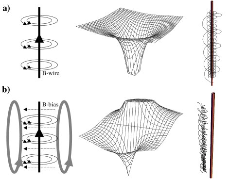
For “parallel” to , (), the atom is in its high field seeking state, and the interaction between the atom and the wire is attractive (see Fig. 1). The atoms in this state can be trapped and move in Kepler-like orbits around the wire [3, 4, 5, 6].
Side guide: Combining the field of the current carrying wire with a homogeneous magnetic bias field perpendicular to the wire breaks the rotational symmetry resulting in unstable orbits for the strong field seeking atoms [7]. In addition the bias field has the effect of exactly canceling the circular magnetic field of the wire along a line parallel to the wire at a distance . Around this line the magnetic field increases in all directions and forms a tube with a magnetic field minimum in its center. Atoms in the low field seeking state () can be trapped in this tube and guided along the wire as shown in Fig. 1b.
Our experiments investigating the Kepler- and side guides are carried out in four steps:
(a) First we load about lithium atoms into a magnetic optic trap (MOT) [8], displaced typically 1 mm from a m thick and long tungsten wire. The MOT is loaded at a distance to the wire in order to prevent trap losses due to atoms hitting the wire [9].
(b) After loading the trap we shut off the slower beam and shift the atoms within ms to the position where they are loaded into the atom guide. This shifting is done by applying an additional magnetic offset field and moving the center of the magnetic quadrupole field, which defines the position of the MOT. Simultaneously the frequency and intensity of the trapping lasers are changed to control the size and temperature of the atom cloud (typically 1.6 mm diameter(FWHM) and T 200 K which corresponds to a velocity of about 0.5 m/s).
(c) We then release the atoms from the MOT by switching off the laser light, the MOT magnetic fields, and the shifting fields within ms. At this point the current through the wire (typically 1 A) and, if desired, a bias magnetic field is switched on within s. From then on the atoms move in the tailored guiding potential. Starting from an initially well localized atom cloud the density distribution expands and changes shape according to the forces on the atoms.
(d) After a given guiding/trapping time, the spatial distribution of the atoms is measured by imaging the fluorescence from optical molasses [2] using a CCD camera. For this the guiding fields (current through the wire and bias field) are switched off and molasses laser beams are switched on for a short time (typically ms). Pictures are taken from above (looking in wire direction) and from the side (looking onto the wire from an orthogonal direction). This allows to study both, the radial confinement and the guiding of the atoms along the wire.
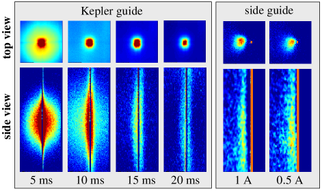
Typical pictures of atoms orbiting around the wire (Kepler guide) and being guided on the side of the current carrying wire (side guide) are shown in Fig. 2. The left set of graphs visually demonstrates loading and guiding of atoms with the Kepler guide: The atoms are released from the MOT at in the center of the wire. Some fraction of these atoms will be bound by the guiding potential, the rest forms an expanding cloud that quickly fades away within about 15 ms. The bound atoms are guided along the wire corresponding to their initial velocity component in this direction. Consequently a cylindrical atomic cloud forms around the wire that expands along the wire. For long guiding times the bound atoms leave the field of view, and the fluorescence signal of the atoms decreases. The top view images show a round atom cloud that is centered on the wire suggesting that atoms circle around the wire.
The graphs on the right hand side of Fig. 2 show atoms that are bound to the side guide after 20 ms of guiding time. In the given examples two different currents (1 A and 0.5 A) were sent through the wire. The distance of the guide from the wire changes clearly with the current.
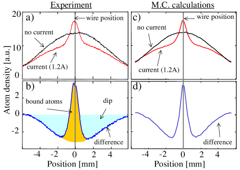
The CCD pictures can be used for further analysis as illustrated in figure 3 for the Kepler guide. For this the CCD images are integrated yielding a projection of the density distribution of the atoms in a direction perpendicular to the wire. Figure 3a shows two such distributions: One corresponding to free expansion of the atomic cloud with no current through the wire. This yields a Gaussian distribution which is typical for atoms released from a MOT. The other one, corresponding to atoms interacting with a current carrying wire, exhibits a pronounced peak centered around the wire which can be attributed to trapped atoms orbiting the wire. The peak sits on top of the broad distribution of non-trapped atoms. In order to extract only the effects of the magnetic guiding potential on the atomic cloud, the two curves are subtracted from each other (Fig. 3b). The peak of the trapped atoms now sits in a broader dip, which is caused by repulsion of atoms in low field seeking states from the wire and by the fact that atoms trapped around the wire are now missing from the expanding atomic cloud. Our experimental data agree well with numerical simulations of the atomic density distributions as shown in Fig. 3c,d.
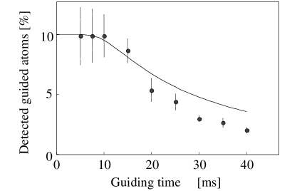
From fits to these experimental data we can extract quantitative information on the guiding of atoms. As an example Fig. 4 shows the number of detected atoms that are bound to the Kepler guide as a function of guiding time. The data is given as the fraction of the total number of atoms of the MOT. The observed number of guided atoms decreases with time mainly because the expanding atomic cloud leaves the detection region given by the 2 cm diameter laser beams. The solid line represents a corresponding calculation of how the atomic signal is expected to fall due to the free expansion of the atomic cloud along the wire and the falling under the influence of gravity. We attribute the additional loss observed in the experiment to magnetic stray fields that render the atomic orbits unstable, i.e. atoms will hit the wire and are lost. There will also be a small contribution to the losses because of a decrease in the wire current over time, caused by the increasing resistance due to ohmic heating of the wire.
From Fig. 4 we can also extract the absolute loading efficiency for atoms from the MOT into the guide. In agreement with Monte Carlo calculations we find loading efficiencies in the range of 10 % for the Kepler guide.
Using the same wire current, the loading of the side guide is less efficient (up to loading efficiency), mainly due to the smaller depth and ‘size’ of the side guide potential.
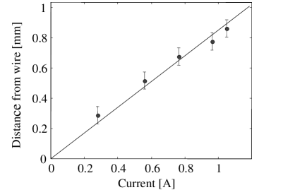
However, the side guide exhibits interesting scaling properties: Its trap depth is given by the magnitude of the bias field. With a fixed trap depth the trap size and its distance from the wire can be controlled by the current in the wire. The paradoxical situation arises that the trap gets smaller (size ) and steeper (gradient ) for decreasing current in the wire. The smallest and steepest trap achievable with a fixed bias field is only limited by the requirement that it must be located outside the wire. A simple calculation shows for example that a trap with a gradient of over 1000 Gauss/cm can be achieved with a moderate current of 0.5 A and an offset field of 10 Gauss. The trap would be located 100 m away from the wire center. Figure 5 illustrates the linear scaling of , the distance of the side guide from the wire, as a function of the wire current (see also the right hand side of Fig. 2).
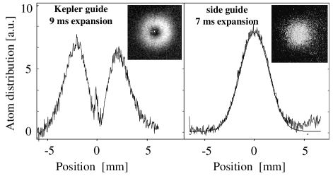
Other interesting information about the transverse confinement can be extracted by measuring the momentum distribution of the trapped atoms. This can be accomplished by ballistic expansion after switching off the guiding potentials. After a few ms of expansion the spatial distribution well represents the velocity distribution of the atoms. Figure 6 shows the spatial atomic distribution 9 (7) ms after switching off the guides. A clear distinction can be seen between the two types of guides. Atoms in the Kepler guide, where atoms circle around the wire, expand in a ring (Fig. 6a), showing clearly that there are no zero-velocity atoms. This is because in order to be trapped in stable orbits around the wire the atoms need sufficient angular momentum and therefore velocity. Atoms with too little angular momentum hit the wire and are lost. The low field seeker atoms of the side guide, however, do not have this constraint. Their velocity distribution is a standard Gaussian (Fig. 6b).
In conclusion we presented two novel methods to build guides for cold atoms, by using potentials created by a current carrying wire: Guiding strong field seekers in Kepler-like orbits around a wire and guiding weak field seekers in a potential tube along the side of a wire. These atom guides represent promising techniques for future applications in atom optics, because of their simplicity and versatility. For example by combining different wires we can construct beam splitters [11], interferometers and more complex matter wave networks [12]. Achieving the ultra high vacuum (UHV) conditions required for coherent guiding is very simple, since the propagation of atoms is in the open and not in an enclosed space like for hollow optical fibers [13].
In addition side guides can be mounted on a surface, so that atoms are guided above the surface along the wires. This renders the wires more stable and at the same time allows for efficient cooling which enables also thin wires to support sizeable currents (see also [14]). Therefore we believe to have now a method for miniaturization and integration of many atom optical elements into one single quantum circuit in the near future, creating mesoscopic atom optics similar to mesoscopic quantum electronics.
We thank A. Zeilinger for his generous support throughout the work. This work was supported by the Austrian Science Foundation (FWF), project S065-05, the Jubiläums Fonds der Österreichischen Nationalbank, project 6400, and by the European Union, contract Nr. TMRX-CT96-0002.
REFERENCES
- [1] For an overview see: C.S. Adams, M. Sigel, J. Mlynek, Phys. Rep. 240, 143 (1994); Atom Interferometry, edited P. Berman (Academic Press, 1997) and references therein.
- [2] A good overview of laser cooling is given in: Laser Manipulation of Atoms and Ions, edited by E. Arimondo, W.D. Phillips, and F. Strumia (North Holland, 1992); and S. Chu, Rev. Mod. Phys. 70, 685 (1998); C. Cohen-Tannoudji, Rev. Mod. Phys. 70, 707 (1998); W.D. Phillips, Rev. Mod. Phys. 70, 721 (1998).
- [3] V. V. Vladimirskii, Sov. Phys. JETP 12, 740 (1961).
- [4] J. Schmiedmayer in XVIII International Conference on Quantum Electronics: Technical Digest, edited by G. Magerl (Technische Universität Wien, Vienna 1992), Series 1992, Vol. 9, 284 (1992); Appl. Phys. B 60, 169 (1995); Phys. Rev. A 52, R13 (1995).
- [5] Actually the adiabatic approximation results in an additional precession of the Kepler orbits around the wire as described in: J. Schmiedmayer and A. Scrinzi, Phys. Rev. A 54, R2525 (1996); JEOS 8, 693 (1996).
- [6] For quantum calculations see: G. P. Pron’kov and Yu. G. Stroganov, Zh. Eksp. Teor. Fiz. 72, 2048 (1977) [Sov. Phys. JETP 45, 1075 (1977)]; R. Blümel and K. Dietrich, Phys. Lett. A 139, 236 (1989); Phys. Rev. A 43, 22 (1991); A. I. Voronin, Phys. Rev. A 43, 29 (1991); L. Hau, J. Golovchenko, M. Burns, Phys. Rev. Lett. 74, 3138 (1995).
- [7] With the rotational symmetry broken, angular momentum is no longer conserved. This results in unstable orbits for the strong field seeking atoms, and they will finally hit the wire.
- [8] The atoms are loaded into the MOT for 20 sec out of an effusive thermal beam at a red laser detuning of 25 MHz and a total beam power of about 150 mW. An electro-optic modulator produces sidebands of 812 MHz (30%) one of which is used as a repumper. To increase the loading rate by a factor of 5 we use an additional 20 mW slower beam with a red detuning of about 100 MHz directed through the MOT into the oven.
- [9] J. Denschlag, G. Umshaus, and J. Schmiedmayer, Phys. Rev. Lett. 81, 737 (1998).
- [10] E.L. Raab et al., Phys. Rev. Lett. 59, 2631 (1987).
- [11] In our lab we are currently experimentally testing an atomic beamsplitter that is formed by two intersecting current carrying wires.
- [12] J. Schmiedmayer Habilitationsschrift Universität Innsbruck (1996); J. Denschlag and J. Schmiedmayer in Proceedings of the International Quantum Coherence Conference, (1997), Boston, World Scientific; J. Schmiedmayer, (1998), EPJ D in print.
- [13] Guiding in hollow fibers is a standard technology in neutron optics: M.A. Kumakhov, V.A. Sharov, Nature 357, 390 (1992); H. Chen et al., Nature 357, 391 (1992). Guiding atoms in hollow optical fibers was proposed by: M.A. Ol’Shanii, Yu.B. Ovchinnikov, V.S. Letokhov, Opt. Comm. 98, 77 (1993); S. Marksteiner, C.M. Savage, P. Zoller, S.L. Rolston, Phys. Rev. A 50, 2680 (1994); and experimentally demonstrated by: M.J. Renn et al., Phys. Rev. Lett. 75, 3253 (1995).
- [14] M. Drndic et al., Appl. Phys. Lett. 72, 2906 (1998).