Method of quantum computation with “hot” trapped ions
Abstract
We present a novel method of performing quantum logic gates in trapped ion quantum computers which does not require the ions to be cooled down to their vibrational center of mass (CM) mode ground state. Our scheme employs adiabatic passages and the conditional phase shift first investigated by D’Helon and Milburn (C. D’Helon and G.J. Milburn, Phys. Rev. A 54, 5141 (1996)).
pacs:
PACS numbers: 03.67.Lx, 42.50.Vk, 32.80.PjNot long ago it was recognized by a number of workers that computations exploiting the quantum mechanical features of nature can perform efficiently certain tasks which are intractable with a classical computer [1, 2, 3]. This discovery has motivated intensive research into apparatus which could be used to perform quantum logic operations on single or multiple quantum two-level systems (“qubits”). Several possible physical implementations have been suggested. They include bulk nuclear magnetic resonance (NMR) [4], which was recently used to execute for the first time a quantum algorithm [5]. However, there will be very serious problems in implementing large scale computations using high temperature bulk NMR [6]. A scalable low-temperature NMR device has been proposed [7], but there exist many formidable technological problems to be overcome before even simple quantum logic operations can be performed using it. Thus at the moment, ion trap quantum computation, first proposed by Cirac and Zoller [8], and demonstrated experimentally shortly afterwards [9], is, arguably, the most promising quantum computation technology for realizing systems of dozens of qubits in the foreseeable future. An ion trap quantum computer consists of a string of ions in a linear radio-frequency trap. Two internal states of the ion compose each qubit and the center of mass (CM) vibrational mode of the ions’ collective oscillations acts as a quantum information bus, by means of which quantum logic gate operations can be performed between pairs of ions.
The most daunting technological problem to be overcome in the realization of ion trap quantum computation is the very fragile nature of the quantum mechanical ground-state of the CM mode. Cooling and maintaining the ions in this ground state is required for performing logic gates in the manner proposed by Cirac and Zoller [8]. Any “heating” (i.e. excitation by external fields) will diminish the accuracy of a logic gate, thus leading to unreliable performance of the quantum computer as a whole, and maybe making the implementation of even simple algorithms impossible. Eliminating all of the possible causes of heating is a very demanding task. Thus it is desirable to investigate methods for performing quantum logic gates without the necessity of being in the ground state of the CM mode.
Recently, three schemes to avoid the heating problem have been proposed: The first approach [10] very elegantly adapts ideas from atom interferometry. Consider two ions confined in a trap: Using a laser beam, one of the ions can be given a state-dependent momentum kick, so that it evolves in time into two spatially resolvable wavepackets, corresponding to the two internal qubit states. Because the second ion is strongly coupled to the first ion by the Coulomb repulsion, it too will evolve into two wavepackets. Since these wavepackets can be resolved using a laser, one of them can be given a -pulse dependent on the state of the first ion, i.e. a quantum gate can be realized. One major problem with that scheme is that it is not scalable up to more than two ions, thus making it not very useful for quantum computation. Another potential difficulty is that it is advisable to use peculiar trapping potentials (e.g. an axial confining potential instead of the more usual harmonic confining potential). A second scheme for quantum computation has recently been proposed [11] (see also [12]). The ions oscillations have many modes other than the center of mass mode [14]. As has been shown both theoretically and experimentally [11, 12], the heating rate of these “higher” modes is much smaller than that of the CM mode. Thus these relatively more stable modes can be used as a quantum bus instead of the unstable CM mode. Drawbacks of this scheme are: the strength of the coupling of each ion to those higher order modes varies from ion to ion, making it harder to adjust the pulse durations; the higher modes are closer together in frequency space, thus making them harder to resolve; and also there is a ‘Debye-Waller’ factor due to heating of the CM mode which alters the strength of the laser interaction by an undetermined factor. The third scheme [13] which has been proposed very recently involves the use of two laser beams driving transitions between virtual levels detuned from phonon resonances.
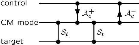
In this Letter we propose an entirely different approach to the problem of performing quantum logic with ‘hot’ trapped ions. We make use of the fact that although the ions are not necessarily in the CM mode ground state, they all share the same CM mode, thus enabling them to interact with each other. Our scheme performs a controlled-rotation (CROT) gate between a pair of ions designated control () and target (). This gate operation consists of a condtional sign change which takes place only if both ions are in the excited state. It can be realized by a sequence of four laser pulses, illustrated symbolically in figure 1.
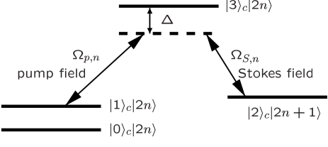
We first do a conditional phase shift between the target qubit and the CM phonon mode which changes the sign of the wavefunction only if the CM mode has an odd excitation and the target ion is in its excited state. This operation can be performed by applying a detuned laser pulse of well defined duration with the ion at the node of a standing wave of the addressing laser [17]. The next step is to put an additional phonon into the CM mode, conditional on the state of the control ion. This is realized by an adiabatic passage between the excited state and some auxiliary state of the control ion, which at the same time puts a single phonon into the CM mode (see figure 2), thereby changing an even phonon state to an odd phonon state (and vice-versa). The advantage of using adiabatic passage for this step is that the operation can be carried out independent of the number of phonons. The next step is to perform a second conditional sign change . Finally we disentangle the ion states from the CM mode by performing the adiabatic passage backwards. As will be shown in detail below, these four pulses produce the desired quantum logic gate regardless of the initial state of the phonon mode. We will now describe those steps in detail. First let us consider the various laser-ion interactions we will need.
To simplify our analysis we will assume that the CM phonon mode is in a pure state given by the following formula:
| (1) |
where are a set of unknown complex coefficients and is the Fock state of occupation number . It will be convienent in what follows to introduce the odd and even parts of this wavefunction, viz.:
| (2) | |||||
| (3) |
We will also use the following notation for phonon states to which a single quantum has been added:
| (4) | |||||
| (5) |
The conditional phase change between odd phonon number states and the excited internal state of an ion can be carried out using an effect first considered by D’Helon and Milburn [17]. They introduced a Hamiltonian for a two-level ion at the node of a detuned classical standing wave. In the limit of large detuning and for interaction times much greater than the vibrational period of the trap, this Hamiltonian for the th ion is
| (6) |
where is the population inversion operator for the th ion, and are the annihilation and creation operators of the CM mode, and . Here is the Lamb-Dicke parameter, is the Rabi frequency for the transitions between the two internal states of the ions, is the total number of ions and the detuning between the laser and the electronic transition. If we choose the duration of this interaction to be , the time evolution is represented by the operator
| (7) |
This time evolution flips the phase of the ion when the CM mode is in an odd state and the ion is in its excited state, thus providing us with a conditional phase shift for an ion and the CM mode.
The adiabatic passage [15] which we require for our gate operation can be realized as follows: We use two lasers, traditionally called the pump and the Stokes field. The pump laser is polarized to couple the qubit state to some second auxiliary state and is detuned by an amount . The Stokes laser couples to the red side band transition , with the same detuning . If the population we want to transfer adiabatically is initially in the state , we turn on the Stokes field (i.e. the sideband laser) and then slowly turn on the pump field (i.e. the carrier laser) until both lasers are turned on fully. Then we slowly turn off the Stokes laser: this is the famous “counter-intuitive” pulse sequence used in adiabatic passage techniques [15]. The adiabatic passage has to be performed very slowly. The condition in our scheme is that , where is the duration of the adiabatic passage and () are the effective Rabi frequencies for the pump and the Stokes transition, respectively [16]. Using the adiabatic passage we can transfer the population from to . To invert the adiabatic passage, we just have to interchange the roles of the pump and the Stokes field. We will denote the adiabatic passage by operators and defined as follows:
| (8) | |||||
| (9) |
Putting all those operations together in detail we can write down the step-by step states for our gate. We first perform the controlled phase shift between the target ion and the CM mode. Since this involves distinguishing even and odd CM mode states, we split them up in our representation, as described above.
| (11) | |||||
| (13) | |||||
| (15) | |||||
| (17) | |||||
The next step is the adiabatic passage as illustrated in fig. 2 and explained above.
| (20) | |||||
| (22) | |||||
| (24) | |||||
| (26) | |||||
The next step is the conditional phase flip on the target ion and the CM mode:
| (29) | |||||
| (31) | |||||
| (33) | |||||
| (35) | |||||
The last step is the adiabatic passage backwards and the inversion of the rotation on the target ion:
| (38) | |||||
| (40) | |||||
| (42) | |||||
| (44) | |||||
Thus we end up with a controlled rotation gate between the ions and . A controlled-NOT (CNOT) gate can be realized by performing rotation pulses on the target qubit both before and after this series of operations.
For simplicity, we have analyzed these operations under the assumption that the state of the phonon CM mode can be described by an arbitrary pure state. More generally, one must assume that the CM mode is in a mixed state, because it can be entangled with some unknown external quantum system, for example the electromagnetic field causing the heating. Provided we assume that this external system does not become entangled with internal degrees of freedom of the qubits, one can quite easily analyze the gate using a density matrix formalism appropriate for mixed states. Since the adiabatic passage and the conditional phase shift all work for arbitrary CM mode phonon states, our principal result, that gate operations can be performed between arbitrary pairs of qubits, can be shown to be true under these circumstances.
A possible source of error in performing gate operations using this scheme is the heating during gate operations. To perform logic operations, effectively the quantum information stored in the two levels of the control qubit is transferred to the even and odd states of the CM mode. Heating mixes these two states, thereby degrading the information stored. Since heating in ion traps is due to variuos sources of noise which have to be treated and modeled differently, this is a very involved problem which will be addressed in future work.
This work was performed while one of us (S.S.) was visiting Los Alamos National Laboratory; she would like to thank Richard Hughes and the other members of the quantum information team there for their hospitality. She also acknowledges financial support from an University of Queensland Postgraduate Research Scholarship, from the Centre for Laser Science and from the Fellowship Fund - Branch of AFUW Qld. Inc. The authors would like to thank Ignacio Cirac, Richard Hughes, Brian King, Paul Kwiat, Hideo Mabuchi, Jörg Steinbach, Gil Toombes and Dave Wineland for useful discussions and comments. This work was supported by the U.S. National Security Agency and the Australian Research Council International Program.
REFERENCES
- [1] D. Deutsch and R. Jozsa, Proc. R. Soc. Lond. A 439 553 (1992).
- [2] P.W. Shor in Proceedings of the 35th Annual Symposium on the Foundations of Computer Science, S. Goldwasser, ed., (IEEE Computer Society Press, Los Alamitos CA, 1994).
- [3] L.K. Grover in Proceedings of the 28th Annual ACM Symposium on the Theory of Computing” (ACM Press, New York, 1996) p. 212.
- [4] N.A. Gershenfeld and I.L. Chuang, Science 275, 350 (1997).
- [5] I.L. Chuang, N. Gershenfeld and M. Kubinec, Phys. Rev. Lett. 80, 3408 (1998); I.L. Chuang et al., Nature 393, 143 (1998).
- [6] W.S. Warren, Science 277, 1688 (1997).
- [7] B.E. Kane, Nature 393, 133 (1998).
- [8] J.I. Cirac and P. Zoller, Phys. Rev. Lett. 74, 4091 (1995).
- [9] C. Monroe et al., Phys. Rev. Lett. 75, 4714 (1995).
- [10] J.F. Poyatos, J.I. Cirac, and P. Zoller, ’Quantum gates with “hot” trapped ions’, submitted to Phys. Rev. Lett. (1998); quant-ph/9712012.
- [11] B.E. King et al., Phys. Rev. Lett., in press (1998); quant-ph/9803023.
- [12] D.F.V. James, Phys. Rev. Lett. 81, 317 (1998).
- [13] A. Sørensen and K. Mølmer, “Quantum computation with ions in thermal motion”, preprint, 1998.
- [14] D.F.V. James, Appl. Phys. B 66, 181 (1998).
- [15] K. Bergmann and B.W. Shore, “Coherent Population Transfer”, in: Molecular Dynamics and Spectroscopy by Stimulated Emission Pumping, H.-L. Dai and R.W. Field, eds. (World Scientific, Singapore, 1995).
- [16] S. Gasiorowicz, Quantum Physics, 2nd ed. (John Wiley & Sons, New York, 1996).
- [17] C. D’Helon and G.J. Milburn, Phys. Rev. A 54, 5141 (1996).
- [18] S. Schneider, H.M. Wiseman, W.J. Munro, and G.J. Milburn, Fortschritte der Physik 46, 391 (1998).