Trapped Ion Quantum Computer Research at Los Alamos
Abstract
We briefly review the development and theory of an experiment
to investigate quantum computation with
trapped calcium ions. The ion trap, laser and ion requirements
are determined, and the parameters required for simple quantum logic
operations are described.
(LAUR 98-314)
1 Introduction
In the last 15 years various authors have considered the generalization of information theory concepts to allow the representation of information by quantum systems. The introduction into computation of quantum mechanical concepts, in particular the superposition principle, opened up the possibility of new capabilities, such as quantum cryptography [1], that have no classical counterparts. One of the most interesting of these new ideas is quantum computation, first proposed by Benioff [2]. Feynman [3] suggested that quantum computation might be more powerful than classical computation, a notion which gained further credence through the work of Deutsch [4]. However, until quite recently quantum computation was an essentially academic endeavor because there were no quantum algorithms that exploited this power to solve useful computational problems, and because no realistic technology capable of performing quantum computations had been envisioned. This changed in 1994 when Shor discovered quantum algorithms for efficient solution of integer factorization and the discrete logarithm problem [5, 6], two problems that are at the heart of the security of much of modern public key cryptography [7]. Later that same year Cirac and Zoller proposed that quantum computational hardware could be realized using known techniques in the laser manipulation of trapped ions [8]. Since then interest in quantum computation has grown dramatically, and remarkable progress has been made: a single quantum logic gate has been demonstrated with trapped ions [9]; quantum error correction schemes have been invented [10, 11]; several alternative technological proposals have been made [21, 22, 23, 24, 25, 26] and quantum algorithms for solving new problems have been discovered [16, 17, 18, 19]. In this paper we will review our development of an experiment to investigate the potential of quantum computation using trapped calcium ions [15].
The three essential requirements for quantum computational hardware are: (1) the ability to isolate a set of two-level quantum systems from the environment for long enough to maintain coherence throughout the computation, while at the same time being able to interact with the systems strongly enough to manipulate them into an arbitrary quantum state; (2) a mechanism for performing quantum logic operations: in other words a “quantum bus channel” connecting the various two-level systems in a quantum mechanical manner; and (3) a method for reading out the quantum state of the system at the end of the calculation.
All three of these requirements are in principle met by the cold trapped ion quantum computer. In this scheme each qubit consists of two internal levels of an ion trapped in a linear configuration. In order to perform the required logic gates, a third atomic state known as the auxiliary level is required. The quantum bus channel is realized using the phonon modes of the ions’ collective oscillations. These quantum systems may be manipulated using precisely controlled laser pulses. Two distinct types of laser pulse are required: “V” type pulses, which only interact with the internal states of individual ions, and “U” type pulses which interact with both the internal states and the external vibrational degrees of freedom of the ions. These interactions can be realized using Rabi flipping induced by either a single laser or Raman (two laser) scheme (Fig.2). Readout is performed by using quantum jumps. This scheme was originally proposed by Cirac and Zoller in 1994 [8], and was used to demonstrate a CNOT gate shortly afterwards [9].

As we can only give the briefest of description of the principles of quantum computation using cold trapped ions, the reader is recommended to peruse the more detailed descriptions which can be found elsewhere [12, 13, 14, 15]. In this paper we intend to focus on the experimental issues involved in building a trapped ion quantum computer.
2 Choice of Ion
There are three requirements which the species of ion chosen for the qubits of an ion trap quantum computer must satisfy:
1. If we use the single laser scheme, the ions must have a level that is sufficiently long-lived to allow some computation to take place; this level can also be used for sideband cooling.
2. the ions must have a suitable dipole-allowed transition for Doppler cooling, quantum jump readout and for Raman transitions (if we chose to use two sub-levels of the ground state to form the qubit);
3. These transitions must be at wavelengths compatible with current laser technology.
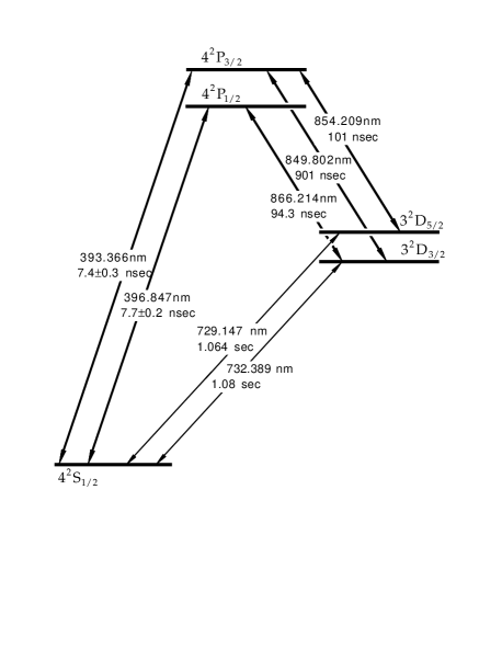
Various ions used in atomic frequency standards work satisfy the first requirement. Of these ions, offers the advantages of transitions that can be accessed with titanium-sapphire or diode lasers and a reasonably long-lived metastable state. The relevant energy levels of the isotope are shown in fig.3.
The dipole-allowed transition from the ground state to the level with a wavelength of 397 nm can be used for Doppler cooling and quantum jump readout; The 732 nm electric quadrupole transition from the ground state to the metastable level (lifetime ) is suitable for sideband cooling. In the single laser computation scheme, the qubits and auxiliary level can be chosen as the electronic states
This ion can also be used for Raman type qubits, with the two Zeeman sublevels of the ground state forming the two qubit states and , with one of the sublevels of the level being the upper level . A magnetic field of 200 Gauss should be sufficient to split these two levels so that they can be resolved by the lasers. The pump and Stokes beams would be formed by splitting a 397nm laser into two, and shifting the frequency of one with respect to the other by means of an acousto-optic or electro-optic modulator. This arrangement has a great advantage in that any fluctuations in the phase of the original 397nm laser will be passed on to both the pump and Stokes beams, and will therefore be canceled out, because the dynamics is only sensitive to the difference between the pump and Stokes phases. One problem in realizing the Raman scheme in is the absence of a third level in the ground state that can act as the auxiliary state required for execution of quantum gates. This difficulty could be removed by using the alternative scheme for quantum logic recently proposed by Monroe et al. [27]; alternatively, one could use an isotope of which has non-zero nuclear spin, thereby giving several more sublevels in the ground state due to the hyperfine interaction; other possibilities that have been suggested for an auxiliary state with in the Raman scheme are to use a state of a phonon mode other than the CM mode [28] or one of the sublevels of the doublet [29].
3 The Radio Frequency Ion Trap
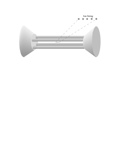
Radio-frequency (RF) quadrupole traps, also named “Paul traps” after their inventor, have been used for many years to confine electrically charged particles [30] (for an introduction to the theory of ion traps, see refs. [31, 32]). The classic design of such a Paul trap has a ring electrode with endcap electrodes above and below, with the ions confined to the enclosed volume. A single ion can be located precisely at the center of the trap where the amplitude of the RF field is zero. But when several ions are placed into this trapping field, their Coulomb repulsion forces them apart and into regions where they are subjected to heating by the RF field. For this reason in our experiment ions are confined in a linear RF quadrupole trap [15]. Radial confinement is achieved by a quadrupole RF field provided by four 1 mm diameter rods in a rectangular arrangement. Axial confinement is provided by DC voltages applied to conical endcaps at either end of the RF structure; the endcap separation is 10 mm. The design of the trap used in these experiments is shown in diagrammatically in Fig.4.
The main concerns for the design are to provide sufficient radial confinement to assure that the ions form a string on the trap axis after Doppler cooling; to minimize the coupling between the radial and axial degrees of freedom by producing radial oscillation frequencies significantly greater than the axial oscillation frequencies; to produce high enough axial frequencies to allow the use of sideband cooling[33]; and to provide sufficient spatial separation to allow individual ions to be addressed with laser beams.
4 Laser Systems
The relevant optical transitions for ions are shown in Fig.5. There are four different optical processes employed in the quantum computer; each places specific demands on the laser system.
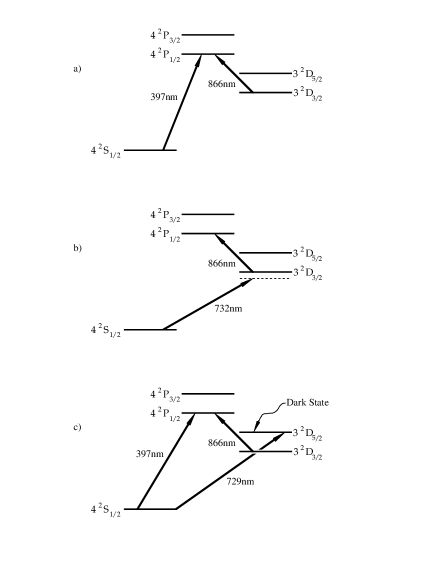
The first stage is to cool a small number of ions to their Doppler limit in the ion trap, as shown in Fig.5a. This requires a beam at 397 nm, the resonant transition. Tuning the laser to the red of the transition causes the ions to be slowed by the optical molasses technique [34]. In this procedure, a laser beam with a frequency slightly less than that of the resonant transition of an ion is used to reduce its kinetic energy. Owing to the Doppler shift of the photon frequency, ions preferentially absorb photons that oppose their motion, whereas they re-emit photons in all directions, resulting in a net reduction in momentum along the direction of the laser beam. Having carefully selected the trap parameters, many cycles of absorption and re-emission will bring the system to the Lamb-Dicke regime, leaving the ions in a string-of-pearls geometry. We have recently found ion crystals of up to five ions.
In order to Doppler cool the ions, the demands on the power and linewidth of the 397 nm laser are modest. The saturation intensity of ions is , and the laser linewidth must be less than . An optogalvonic signal obtained with a hollow cathode lamp suffices to set the frequency. We use a Titanium:Sapphire (Ti:Sapphire) laser (Coherent CR 899-21) with an internal frequency doubling crystal to produce the 397 nm light.
During the Doppler cooling, the ions may decay from the state to the state, whose lifetime is To empty this metastable state, we use a second Ti:Sapphire laser at 866 nm.
Once the string of ions is Doppler cooled to the Lamb-Dicke regime, the second stage of optical cooling, sideband cooling, will be used to reduce the collective motion of the string of ions to its lowest vibrational level [35], illustrated in Fig.5b. In this regime, a narrow optical transition, such as the 732 nm dipole forbidden transition, develops sidebands above and below the central frequency by the vibrational frequencies of the ions. The sidebands closest to the unperturbed frequency correspond to the CM vibrational motion. If is the optical transition frequency and the frequency of the CM vibrational motion, the phonon number is increased by one, unchanged, or decreased by one if an ion absorbs a photon of frequency , or , respectively. Thus, sideband cooling is accomplished by optically cooling the string of ions with a laser tuned to .
The need to resolve the sidebands of the transition implies a much more stringent requirement for the laser linewidth; it must be well below the CM mode vibrational frequency of . The laser power must also be greater in order to pump the forbidden transition. We plan to use a Ti:Sapphire laser locked to a reference cavity to meet the required linewidth and power. At first glance it would seem that, with a metastable level with a lifetime of 1s, no more than 1 phonon per second could be removed from a trapped ion. A second laser at 866 nm is used to couple the state to the state to reduce the effective lifetime of the D state and allow faster cooling times. The transitions required for realization of quantum logic gates and for readout, discussed in detail in sections 5.2 and 5.3, are shown in Fig.5c. These can be performed with the same lasers used in the Doppler and sideband cooling procedures.
There are two other considerations concerning the laser systems for quantum computation which should be mentioned. To reduce the total complexity of the completed system, we are developing diode lasers and a frequency doubling cavity to handle the Doppler cooling and quantum jump read out. Also complex quantum computations would require that the laser on the computation transition have a coherence time as long as the computation time. This may necessitate using qubits bridged by Raman transitions as discussed above, which eliminates the errors caused by the phase drift of the laser.
5 Qubit Addressing Optics
In order for the ion qubits to be useful for actual calculations, it will be necessary to address the ions in a very controlled fashion. Our optical system for qubit addressing is shown schematically in fig. 6.
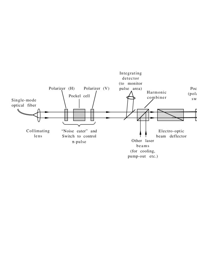
There are two aspects to be considered in the design of such a system: the precise interactions with a single ion; and an arrangement for switching between different ions in the string. In addition to the obvious constraints on laser frequency and polarization, the primary consideration for making exact - or -pulses is control of the area (over time) of the driving light field pulse. The first step toward this is to stabilize the intensity of the laser, as can be done to better than , using a standard “noise-eater”. Such a device typically consists of an electro-optical polarization rotator located between two polarizers; the output of a fast detector monitoring part of the transmitted beam is used in a feedback circuit to adjust the degree of polarization rotation, and thus the intensity of the transmitted light. Switching the light beam on and off can be performed with a similar (or even the same) device. Because such switches can possess rise/fall times on the scale of nanoseconds, it should be possible to readily control the area under the pulse to within , simply by accurately determining the width of the pulse. A more elaborate scheme would involve an integrating detector, which would monitor the actual integrated energy under the pulse, shutting the pulse off when the desired value is obtained.
Once the controls for addressing a single ion are decided, the means for switching between ions must be considered. Any system for achieving this must be fast, reproducible, display very precise aiming and low “crosstalk” (i.e. overlap of the focal spot onto more than one ion), and be as simple as possible. In particular, it is desirable to be able to switch between different ions in the string in a time short compared to the time required to complete a given -pulse on one ion. This tends to discount any sort of mechanical scanning system. Acousto-optic deflectors, which are often used for similar purposes, may be made fast enough, but introduce unwanted frequency shifts on the deviated beams. As a tentative solution, we propose to use an electro-optic beam deflector, basically a prism whose index of refraction, and consequently whose deflection angle, is varied slightly by applying a high voltage across the material; typical switching times for these devices is 10 nanoseconds, adequate for our purposes. One such device produces a maximum deflection of 9 mrad, for a 3000V input. The associated maximum number of resolvable spots (using the Rayleigh criterion) is of order 100, implying that 20 ions could be comfortably resolved with negligible crosstalk.
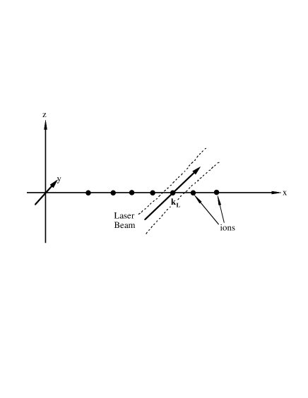
After the inter-ion spacing has been determined, i.e., by the trap frequencies, the crosstalk specification determines the maximum spot size of the addressing beam. For example, for an ion spacing of 20 m, any spot size (defined here as the diameter) less than 21.6 m will yield a crosstalk of less than 0.1, assuming a purely Gaussian intensity distribution (a good approximation if the light is delivered from a single-mode optical fiber, or through an appropriate spatial filter). In practice, scattering and other experimental realities will increase this size, so that it is prudent to aim for a somewhat smaller spot size, e.g. 10 m. One consideration when such small spot sizes are required is the effect of lens aberrations, especially since the spot must remain small regardless of which ion it is deflected on. Employing standard ray-trace methods, we have found that the blurring effects of aberrations can be reduced if a doublet/meniscus lens combination is used (assuming an input beam size of 3mm, and an effective focal length of 30mm). A further complication is that, in order to add or remove phonons from the system, the addressing beams must have a component along the longitudinal axis of the trap. The addressing optics must accommodate a tilted line of focus, otherwise the intensity at each ion would be markedly different, and the crosstalk for the outermost ions would become unacceptable. According to ray-trace calculations, adding a simple wedge (of ) solves the problem and this has been confirmed by measurements using a mock system.
Depending on the exact level scheme being considered, it may be necessary to vary the polarization of the light. Because the electro-optic deflector requires a specific linear polarization, any polarization-control elements should be placed after the deflector. The final result is a highly directional, tightly-focused beam with controllable polarization and intensity.
6 Imaging System
In order to determine the ions’ locations and to readout the result of the quantum computations, an imaging system is required. Our current imaging system consists of two lenses, one of which is mounted inside the vacuum chamber, and a video camera coupled to a dual-stage micro-channel plate (MCP) image intensifier. The first lens with focal length 15 mm collects the light emitted from the central trap region with a solid angle of approximately 0.25 sr. The image is relayed through a 110mm/f2 commercial camera lens to the front plate of the MCP. This set-up produces a magnification of 7.5 at the input of the MCP. The input of the 110 mm lens is fitted with a 400nm narrow band filter to reduce background from the IR laser and from light emanating from the hot calcium oven and the electron gun filament.
The dual plate intensifier is operated at maximum gain for the highest possible sensitivity. This allows us to read out the camera at normal video rate of 30 frames into a data acquisition computer. Averaging and integrating of the signal over a given time period can then be undertaken by software. We find this arrangement extremely useful in enabling us to observe changes of the cloud size or the intensity of the fluorescence with changes of external parameters like trapping potential, laser frequency, laser amplitude, etc. in real time.
The spatial resolution of the system is limited by the active diameter of individual channels of the MCP of approximately 12 m. Since the gain is run at its maximum value cross talk between adjacent channels in the transition between the first and second stage is to be expected. This results in the requirement that two incoming photons can only be resolved when they are separated at the input of the MCP by at least two channels, i.e. by 36 m in our case. With the magnification of the optical system of 7.5 this translates into a minimum separation of two ions to be resolved of 5 m, which is well below the separation of ions in the axial well of about 25 m expected in our experiment.
7 Summary
It is our contention that currently the ion trap proposal for realizing a practical quantum computer offers the best chance of long term success. This in no way is intended to trivialize research into the other proposals: in any of these schemes technological advances may at some stage lead to a breakthrough. In particular, Nuclear Magnetic Resonance does seem to be a relatively straightforward way in which to achieve systems containing a few qubits. However, of the technologies which have so far been used to demonstrate experimental logic gates, ion traps seem to offer the least number of technological problems for scaling up to 10’s or even 100’s of qubits.
In this paper we have described in some detail the experiment we are currently developing to investigate the feasibility of cold trapped ion quantum computation. We should emphasize that our intentions are at the moment exploratory: we have chosen an ion on the basis of current laser technology, rather than on the basis of which ion which will give the best performance for the quantum computer. Other species of ion may well give better performance: In particular Beryllium ions do have the potential for a significantly lower error rate due to spontaneous emission, although it is also true that lighter ions may be more susceptible to heating. Other variations, such as the use of Raman transitions in place of single laser transitions, or the use of standing wave lasers need to be investigated. Our choice of Calcium will allow us to explore these issues. Furthermore, calculations suggest that it should be possible to trap 20 or more Calcium ions in a linear configuration and manipulate their quantum states by lasers on short enough time scales that many quantum logic operations may be performed before coherence is lost. Only by experiment can the theoretical estimates of performance be confirmed [36, 37]. Until all of the sources of experimental error in real devices are thoroughly investigated, it will be impossible to determine what ion and addressing scheme enables one to build the best quantum computer or, indeed, whether it is possible to build a useful quantum computer with cold trap ions at all.
Acknowledgments
This research was funded by the National Security Agency.
References
- [1] R. J. Hughes et al. Contemp. Phys. 36 (1995) 149-163.
- [2] P. A. Benioff, Int. J. Theor. Phys.21 (1982) 177-201.
- [3] R. P. Feynman, Foundations of Physics 16 (1986) 507-531.
- [4] D. Deutsch, Proc. R. Soc. Lond.A 425 (1989) 73-90.
- [5] P. W. Shor, Proceedings of the 35th Annual Symposium on the Foundations of Computer Science, S. Goldwasser ed., IEEE Computer Society Press, Los Alamitos CA, 1994.
- [6] A. Ekert and R. Jozsa, Rev. Mod. Phys. 68 (1996) 733-753.
- [7] R. J. Hughes, “Crptography, Quantum Computation and Trapped Ions”, submitted to Phil. Trans. Roy. Soc. (London), 1997; quant-ph/9712054.
- [8] J. I. Cirac and P. Zoller, Phys. Rev. Lett. 74, (1995) 4094-4097.
- [9] C. Monroe et al., Phys. Rev. Lett. 75 (1995) 4714-4717.
- [10] E. Knill, R. Laflamme and W. Zurek, “Accuracy threshold for quantum computation”; submitted to Science (1997).
- [11] J. Preskill, “Reliable quantum computers”, preprint (1997), quant-ph/9705031.
- [12] A. M. Steane, Applied Physics B 64 (1997) 623-642.
- [13] D. F. V. James, “Quantum dynamics of cold trapped ions, with application to quantum computation”, Applied Physics B, in the press (1998); quant-ph/9702053.
- [14] D. J. Wineland et al., “Experimental issues in coherent quantum-state manipulation of trapped atomic ions”, to be submitted to Rev. Mod. Phys. (1997).
- [15] R. J. Hughes, et al., “The Los Alamos Trapped Ion Quantum Computer Experiment”, Fortschritte der Physik, in the press (1998); quant-ph/9708050.
- [16] L. K. Grover Proceedings of the 28th Annual ACM Symposium on the Theory of Computing, ACM Press, New York, 1996 p.212
- [17] B. M. Terhal and J. A. Smolin, ” Superfast quantum algorithms for coin weighing and binary search problems”, preprint (1997) quant-ph/9705041.
- [18] D. Boneh and R. Lipton, ”Quantum cryptanalysis of hidden linear functions,” Proc. CRYPTO’95 (Springer, New York, 1995)
- [19] A. Kitaev, ”Quantum measurements and the Abelian stabilizer problem,” preprint (1995) quant-ph 9511026.
- [20] T. Pellizzari et al., Phys. Rev. Lett.75 (1995) 3788-3791.
- [21] Q. A. Turchette et al., Phys. Rev. Lett.75 (1995) 4710-4713.
- [22] D. G. Cory, A. F. Fahmy and T. F. Havel, Proc. Natl. Acad. Sci. USA 94 (1997) 1634-1639.
- [23] J. R. Friedman et al., Phys. Rev. Lett. 76 (1996) 3830-3833.
- [24] V. Privman, I. D. Vagner and G. Kventsel, “Quantum computation in quantum-Hall systems”, preprint (1997), quant-ph/9707017.
- [25] M. F. Bocko, A. M. Herr and M. J. Feldman, “Prospects for quantum coherent computation using superconducting electronics”, preprint (1997).
- [26] D. Loss and D. P. DiVincenzo, “Quantum computation with quantum dots” preprint (1997), cond-mat/9701055.
- [27] C. Monroe et al. Phys. Rev. A 55 (1997) R2489.
- [28] A. M. Steane, private communication, 1996.
- [29] R. Blatt, private communication, 1997.
- [30] W. Paul and H. Steinwedel, Z. Naturforsch.A 8 (1953) 448.
- [31] M. G. Raizen et al., Phys. Rev. A 45 (1992) 6493-6501.
- [32] P. K. Ghosh, Ion Traps Clarendon Press, 1995.
- [33] F. Diedrich et al., Phys. Rev. Let. 62 (1989) 403-407.
- [34] S. Stenholm, Rev. Mod. Phys. 58 (1986) 699-739.
- [35] D. J. Wineland and W. M. Itano, Phys. Rev.A 20 (1979) 1521-1540.
- [36] R. J. Hughes, D. F. V. James, E. H. Knill, R. Laflamme and A. G. Petschek, Phys. Rev. Lett. 77 (1996) 3240-3243.
- [37] D. F. V. James, R. J. Hughes, E. H. Knill, R. Laflamme and A. G. Petschek, Photonic Quantum Computing, S. P. Hotaling, A. R. Pirich eds, Proceedings of SPIE 3076 (1997) 42-50.