Basics of Quantum Computation
Abstract
Quantum computers require quantum logic, something fundamentally different to classical Boolean logic. This difference leads to a greater efficiency of quantum computation over its classical counter–part. In this review we explain the basic principles of quantum computation, including the construction of basic gates, and networks. We illustrate the power of quantum algorithms using the simple problem of Deutsch, and explain, again in very simple terms, the well known algorithm of Shor for factorisation of large numbers into primes. We then describe physical implementations of quantum computers, focusing on one in particular, the linear ion–trap realization. We explain that the main obstacle to building an actual quantum computer is the problem of decoherence, which we show may be circumvented using the methods of quantum error correction.
Contents
toc
I Introduction
This review is not intended to cover all developments in the quantum information theory and quantum computation. Our aim is rather to provide the necessary insights for an understanding of the field so that various non-experts can judge its fundamental and practical importance.
Quantum computation is an extremely exciting and rapidly growing field of investigation [7, 33, 90, 63, 62]. An increasing number of researchers with a whole spectrum of different backgrounds, ranging from physics, via computing sciences and information theory to mathematics and philosophy, are involved in researching properties of quantum–based computation. Interplay between mathematics and physics of course has always been beneficial to both types of human activities. The calculus was developed by Newton and Leibniz in order to understand and describe dynamical laws of motion of material bodies. In general, geometry and physics have had a long and successful symbiotic relationship: classical mechanics and Newtonian gravity are based on Euclidean Geometry, whereas in Einstein’s Theory of General Relativity the basis is provided by non-Euclidean, Riemannian geometry, an important insight taken from mathematics into physics. Although this link between Physics and Geometry is still extremely strong, one of the most striking connections today is between Information Theory and Quantum Physics and this will be investigated in the present review.
Speaking somewhat loosely, we observe a trend to make mathematics “more physical”. What lies behind this phrase is the realization that the regularities and structures we observe in mathematics are actually deeply rooted in, and derive from, the experiences of the physical world we happen to inhabit. According to this view, Geometry, for instance, does not have an independent, as it were Platonic, existence, but has to be inferred from making actual measurements and observations in Nature. This thesis, that mathematics cannot be “correct” a priori, but needs to be tested experimentally, was probably first fully realized by Einstein through General Relativity; the most recent example, however, is in the theory of computation. Computation, based on the laws of classical physics, leads to completely different constraints on information processing than computation based on quantum mechanics (first realized by Feynman [35, 36] and Deutsch [26]). This is an extraordinary fact: we will show that quantum information processing is faster, and, in some sense, more efficient than its classical counterpart (for a detailed discussion of the physical basis of computation see [30]).
Today’s computers are classical, a fact which is actually not entirely obvious and is worth elaborating further. A basis of modern computers rests on semiconductor technology. Transistors, which are the “neurons” of all computers, work by exploiting properties of semiconductors. However, the explanation of how semiconductors function is entirely quantum mechanical in nature: it simply cannot be understood classically. Are we thus to conclude that classical physics cannot explain how classical computers work?! Or are we to say that classical computers are, in fact, quantum computers! The answer to both these questions is yes and no. Yes, classical computers are in a certain, restricted, sense quantum mechanical, because, as far as we understand today, everything is quantum mechanical. No, classical computers, although based on quantum physics, are not fully quantum, because they do not use “quantumness” of matter at the information-theoretical level, where it really matters. Namely, in a classical computer information is recorded in macroscopic, two level systems. Wires conducting electrical current in computers can be in two basic states: when there is no current flowing through, representing a logical “0”, or else when there is some current flowing through, representing a logical “1”. These two states form a bit of information. All computation is based on logical manipulation of bits through logical gates acting on wires representing these bits. Imagine, however, that instead of wires and currents we use two electronic states of an atom to record information. Let us call these states the ground state, , and the excited state, (Dirac notation is the most natural for quantum computing). But, since an atom obeys laws of quantum mechanics, the most general electronic state is a superposition of the two basic states
| (1) |
called the quantum bit or qubit, for short (this term was coined by Schumacher [77]). We see that in addition to and states, a qubit has, so to speak, all the states “in between”. When we have two bits, than there are four possibilities: . However, this should be contrasted with two qubits which are in general in a state of the form
| (2) |
If for example and , then we have the famous Einstein-Podolski-Rosen (EPR) state [10]
| (3) |
Two qubits in this state display a degree of correlation impossible in classical physics and hence violate the Bell inequality which is satisfied by all local (i.e. classical) states. This phenomenon is called entanglement and is at the root of the success of quantum computing. We will see how exploitation of a number of entangled qubits can lead to a considerable computational speed-up in a quantum computer over its classical counterpart. Thus what distinguishes classical and quantum computing is how the information is encoded and manipulated, i.e. what plays a crucial role is whether the logical basis is the classical, Boolean logic, or the quantum logic.
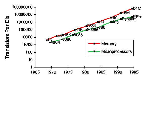
It is important to stress that apart from this theoretically–driven curiosity to investigate quantum computation, there is a practical need to do so, too. This stems from the observation of the rate of technological progress which is known as Moore’s Law. This law states that the number of transistors per chip (i.e. the complexity of computers) grows exponentially with time; more precisely, it doubles every year, as depicted in Fig. 1 (the 1997 special issue of Scientific American is devoted entirely to the technological side of computation [85], including an article about Moore’s Law). We can see that this law has been obeyed almost precisely in the last years. If this exponential growth is extrapolated into the near future we see that, at Moore’s rate, a bit of information will be encoded into a single atom by the year 2017. In fact, even before that, by the year 2012, quantum effects will become very important, so much so that they will have a considerable effect upon computation and should not be neglected any longer. Thus, not only our theoretical curiosity, but also technological progress requires that we study and understand quantum computation.
II Computation in Classical and Quantum Physics
We have noted that classical computation is based on Boolean logic. This logic can be represented in terms of gates acting on particular bits of information. In fact, a classical computer can be viewed as a collection of bits and gates which act on a certain input, i.e. the initial state of bits, to produce via the gate action a certain output, i.e. the final state of bits. We will review some properties of classical gates in the next subsection, and then see how this picture differs in the case of a quantum computer.
A Classical Gates
Let us start with the simplest of logical gates, i.e. one bit gates. What can happen to a single bit? The first possibility is “nothing”, but this is a trivial gate which of course does not alter the state of the bit. Secondly, the value of the bit can turn into and into , which is called a NOT gate. This exhausts all the possibilities for a single bit.
Two bits are much more exciting. A usual two bit gate has two input bits and one output bit. Take, for example, an OR gate: the output of this gate is only if both the input bits are , and otherwise it is (see Fig. 2.). This gate illustrates an important property of classical computers, all of which contain some OR gates. Namely, the OR gate is irreversible, meaning that given the value of the output bits we cannot reconstruct the values of the input bits. So, if the output to the OR gate was , the input could have been , or , i.e. it is simply undetermined. Thus this gate cannot really be run backwards, and hence is called irreversible.
Now, how many two–input–one–output–bit gates are there? Well, there are possible different inputs and each one can have a different output leading to possible different gates. However, not all the gates are necessary: there are sets of gates, called fundamental gates, out of which any other gate can be constructed. For example, using NOT, OR and AND gates we can construct any other gate. A more striking example is a SHEFFER gate out of which any other gate can be constructed as proven by Sheffer [79]. If and are two bits assuming either or values, i.e. and are two binary variables, then this gate can be written as NOT ( OR ), as in Fig. 2. Since any computation, i.e. any combination of any gates on any number of bits, can be written in terms of Sheffer gates only, this gate is called universal.
Another interesting feature of computers based on irreversible gates (i.e. all existing real world computers) is that they dissipate energy as they run [55]. This energy is actually dissipated in the form of heat when the information is deleted in the irreversible gates we described above, as discovered by Landauer [55]. In fact, deleting information always involves investing work and wasting energy [11], as can be illustrated in the following simple example (for a detailed discussion at a simple level see [37]). Consider a container enclosing a single gas atom, as in Fig. 3 a). If the atom is in the left hand half of the container, we take this to represent a logical , and if the atom is in right hand half of the container we take this to represent a logical . Say that initially we do not know where the atom is. Since there are two possibilities for the state of the atom, the entropy of the atom is equal to , where is the Boltzmann constant (this relationship between thermodynamical entropy and information, or uncertainty, was first explicitly emphasised by Shannon in his celebrated Information Theory [78], although it was Szilard who hinted at this relationship much earlier [91]). Deleting this information means finding out what the state of the atom is, i.e. confining the atom to the particular (known) half of the container. To do this, we can, for example, push the right hand wall to the left until the atom is confined entirely to the left hand half, as in Fig. 3 b). If we do this at a constant temperature (most computers work at room temperature anyway!) we get a heat loss of to the environment. Now the same effect is present in any computer and that is why they heat up as they work (in fact, they use much more than per gate: ordinary PCs use about per gate, but is the fundamental thermodynamical limit, as first shown by Landauer [55]).
The reader should be warned, however, that the above example is deceptively simple. The above process can be thermodynamically reversible, in which case the increase in the entropy of environment is compensated by the decrease in the entropy of the atom in the box. In computation, on the other hand, logically irreversible operations are performed on deterministic data, so that the increase in the entropy of the environment is not compensated by a decrease in the entropy of the system, and hence the operation is also thermodynamically irreversible. The question that is then important from the fundamental point of view is whether we can manage without this: can we run computers without any energy dissipation? Surprisingly, the answer is yes! Instead of irreversible gates we have to use reversible gates; it can be shown that reversible gates can perform without any heat loss [11]. In addition, Bennett proved that any irreversible computation can be performed using reversible gates only [11]. So, the crucial question is how to make reversible gates out of irreversible gates.
Let us illustrate the general principle using the OR gate. We emphasised that this gate is irreversible because there is only one output and two inputs, so that information gets lost in the gate. So, we can decide to add another output bit which, for example, “saves” the value of the first input bit as in Fig. 4. Thus, with two inputs and two outputs the resulting gate is reversible. This is, in fact, the general method of constructing reversible out of irreversible gates: we have to save as much of the input as necessary at the output, so that, given that output, we can unambiguously determine the value of the input. In this way all the irreversible computation can be made reversible and, at least in principle, dissipation–free. We stress again that logical reversibility is just a necessary condition for no heat loss, and we have to make the computation thermodynamically reversible as well. Bennett constructed thermodynamical models of computers which dissipated arbitrarily little energy if run sufficiently slow [11], and his review of the field of reversible computation is given in [12]. An interesting model of a billiard ball reversible computer was also developed by Fredkin and Toffoli [38]. We say that these models are reversible “in principle”, because we know that thermodynamical reversible processes are quasi-static idealizations of real processes, which are never exactly true under realistic circumstances.
We will see that this question of reversible computation is not only relevant to heat–free classical computation, but also is of central importance for quantum computing. Next we explain how.
B Quantum Gates
For completeness let us start with some basic definitions. A quantum network is a quantum computing device consisting of quantum logic gates whose computational steps are synchronised in time [26, 35, 36]. The outputs of some of the gates are connected by wires to the inputs of others. The size of the network is governed by its number of gates. The size of the input of the network is governed by its number of input qubits i.e. the qubits that are prepared appropriately at the beginning of each computation performed by the network. Inputs are encoded in binary form in the computational basis of selected qubits often called a quantum register, or simply a register. For instance, the binary form of the number is and loading a quantum register with this value is done by preparing three qubits in the state . In the following we use a more compact notation: stands for the direct product which denotes a quantum register prepared with the value . Computation is defined as a unitary evolution of the network which takes its initial state “input” into some final state “output” (analogous to classical computation).
The entire quantum computation is thus a unitary transformation, where a measurement is performed at the end to extract the result. This will be explained in more detail in the next subsections through a couple of examples. However, a unitary transformation is itself reversible; therefore, we have to use reversible gates introduced previously in order to be able to implement quantum gates. The difference between reversible and quantum computation is that a quantum gate acts on superpositions of different basis states of qubits, whereas classically this option is non–existent. In Fig. 5 we present three basic gates used in quantum computation, the NOT gate, the Controlled NOT gate and the TOFFOLI gate [5]. Controlled NOT gate (CNOT, for short) is a two qubit gate, where the value of the first qubit (called control) determines what will happen to the second qubit (called target) qubit. Namely if the control qubit is , we apply the NOT gate to the target qubit and otherwise nothing happens to it (hence the name Controlled NOT). TOFFOLI gate can be understood as Controlled–Controlled NOT. As in classical computation, there are universal gates in quantum computation. There is, for example, a three qubit gate which is universal, discovered by Deutsch [27], and also a two qubit gate which is universal (e.g. [4]). An extremely useful result of this universality is that any quantum computation can be done in terms of a Controlled NOT gate and a single qubit gate [29, 58] (which varies), although, of course, it might sometimes be more convenient to use other gates as well [4]. An important one qubit gate is the so called Hadamard transformation whose action is the following (the normalization is omitted)
| (4) | |||||
| (5) |
This transformation will be used frequently throughout this review.
Both the input and the output of a quantum computer can be encoded in several registers. Even when is a one–to–one map between the input and the output and the operation can be formally written as a unitary operator
| (6) |
we may still need an auxiliary register to store the intermediate data. When is not a bijection we definitely have to use an additional register in order to guarantee the unitarity (i.e reversibility) of computation. In this case the computation must be viewed as a unitary transformation of (at least) two registers
| (7) |
where the second register is of appropriate size to accommodate . This uses the same principle demonstrated in making the OR gate reversible. We now show a simple, but extremely important use of the Controlled NOT gate.
C Quantum Entanglement
We stressed in the introduction that quantum entanglement is the phenomenon responsible for all the advantages of quantum computation. Here we show how to create entangled quantum states using the simple quantum gates introduced previously. This operation is used time and again in various quantum computations as we will see when reviewing Shor’s quantum algorithm for factorization of natural numbers into primes [80].
To illustrate entanglement we look at the EPR-state of two qubits
| (8) |
We say that a pure state of two qubits is entangled if it cannot be written as a product of the individual states of the two qubits, such as . The EPR state is obviously not decomposable into a direct product of any form, and is therefore entangled. Of course, both of the states and are of the direct product form, but their superposition is not. The interesting question is therefore how to create an EPR state starting from just a disentangled, say, the state. The required quantum computation is very simple: first we apply a Hadamard transformation to the first qubit, and then a Controlled NOT between the first qubit and the second qubit, where the second qubit is the target. These two steps can be written as (the normalization is omitted)
| (9) |
We see that after the action of the Hadamard transformation the qubits are still disentangled. This is because this transformation acts on only one of the qubits, i.e. is applied locally and not globally, and therefore cannot create global features such as entanglement. This is true, in general, implying that no local operation whatsoever can create an entangled state out of a disentangled one, a principle which has a fundamental place in quantum information processing (see e.g. [15, 95, 96, 97, 98]). Only global transformations such as a Controlled NOT can create entanglement.
The above was the first and simplest form of quantum computation involving only two qubits and a few gates. Let us now look at some slightly more complicated examples.
III Simple Quantum Networks
In this section we present some very simple quantum networks. These networks will provide a basis for the more complicated Shor’s algorithm [80] reviewed in the next section.
A Simple Arithmetic
Quantum networks for basic arithmetic operations can be constructed in a number of different ways. Although almost any non-trivial quantum gate operating on two or more qubits can be used as an elementary building block of the networks [4] we have decided to use the three gates described in Fig. 5, hereafter referred to as elementary gates. None of these gates is universal for quantum computation; however, they suffice to build any Boolean functions as the Toffoli gate alone suffices to support any classical reversible computation [92]. The NOT and the Control–NOT gates are added for convenience (they can be easily obtained from the TOFFOLI gates, an exercise we leave to the reader).
B Plain adder
The addition of two registers and is probably the most basic arithmetic operation [94]. In the simplest form it can be written as
| (10) |
Here we will focus on a slightly more complicated (but more useful) operation that rewrites the result of the computation into the one of the input registers, which is the usual way additions are performed in conventional irreversible hardware; i.e.
| (11) |
As one can reconstruct the input out of the output , there is no loss of information, and the calculation can be implemented reversibly. To prevent overflows, the second register (initially loaded in state ) should be sufficiently large, i.e. if both and are encoded on qubits, the second register should be of size . In addition, the network described here also requires a temporary register of size , initially in state , to which the carries of the addition are provisionally written (the last carry is the most significant bit of the result and is written in the last qubit of the second register).
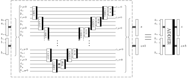
The operation of the full addition network is illustrated in Fig. 6 and can be understood as follows:
-
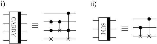
We compute the most significant bit of the result . This step requires computing all the carries through the relation AND AND , where , and represent the th qubit of the first, second and temporary (carry) register respectively. Fig. 7i) illustrates the sub–network that effects the carry calculation.
-
Subsequently we reverse all these operations (except for the last one which computed the leading bit of the result) in order to restore every qubit of the temporary register to its initial state . This enables us to reuse the same temporary register, should the problem, for example, require repeated additions. During the resetting process the other qubits of the result are computed through the relation XOR XOR and stored in the second register, where XOR is the Exclusive OR gate: the output is if the inputs are or , and otherwise is . This operation effectively computes the first digits of the sum (the basic network that performs the summation of three qubits modulo is depicted in Fig. 7ii).)
The addition network has a typical ”V” shape present in any reversible computation which has to dispose of unneccessary information (i.e. garbage). We show in the next section why this is the case. Another interesting feature of the adder is that if we reverse the action of the above network (i.e. if we apply each gate of the network in the reversed order) with the input , the output will produce when . So, with the same network we can also accomplish subtraction! When , the output is , where is the size of the second register. In this case the most significant qubit of the second register will always contain . By checking this “overflow bit” it is therefore possible to compare the two numbers and ; we can use this operation to construct the network for modular addition. The crucial fact is that once we know how to perform a modular addition, we immediately know how to execute modular multiplication [94], since
| (12) |
Likewise we can perform modular exponentiation [94], because
| (13) |
Thus addition is at the root of all the other simple arithmetic operations: subtraction, (modular) multiplication and (modular) exponentiation. It should be noted that multiplication (and therefore exponentiation) can be performed more efficiently than this (see the fastest multiplication algorithm in [76]), however the above will be sufficient for our purposes. Modular operations will become particularly important when we discuss Shor’s algorithm shortly [94]. Next, however, we consider another important problem, i.e. that of garbage reduction.
C Garbage Disposal
We have seen that in order to perform more involved arithmetic operations we need to repeat the simpler ones a number of times. However, each of these simple operations contains a number of additional, auxiliary qubits, which serve to store the intermediate results, but are not relevant at the end. In order not to waste any unneccesary space, it is therefore important to reset these qubits to so that we are able to re–use them. A good example of a procedure which does not generate any garbage is the reversible addition we introduced earlier; all the carry bits were reset to at the end of addition. Quantum mechanically, this reset is even more important. This is because the result of any quantum computation is always entangled with the auxiliary, garbage qubits. Consider the output of the adder network, where the carry qubits are auxiliary. It will be in a superposition of different results each one entangled to a different input and carry ,
| (14) |
For clarity let us consider two terms only,
| (15) |
If the garbage is now reduced to then the total state becomes
| (16) |
i.e. the garbage is disentangled from the rest. If, however, this is not done, and we completely disregard the state of the carries in the further computation then the effective state of the rest of result is obtained by tracing over the states of to obtain,
| (17) |
This state is now a mixed state and is completely disentangled. We have already said that as soon as entanglement disappears, then a quantum computer is no more powerful than a classical computer. Thus resetting the garbage plays a central importance in quantum computation (classical reversible computation does not suffer from this since there is no entanglement in the first place!). More generally, a quantum computer will interact with its environment and become entangled with it in exactly the same way that the carries and the other two registers become entangled. However, the environment is in general impossible to control and this means that the pure superposition states of a quantum computer eventually become mixed (and therefore useless from the quantum computational point of view). This is the most general model of how errors arise in quantum computation, and will be described in more detail later. Here we first present a universal way of dealing with “garbage bits” that arise during a computational process.
Suppose that we have to compute given and given that we know how to reversibly perform
| (18) |
A naive way would be to prepare five registers in the state and then to execute computation of four times
| (19) | |||||
| (20) | |||||
| (21) | |||||
| (22) |
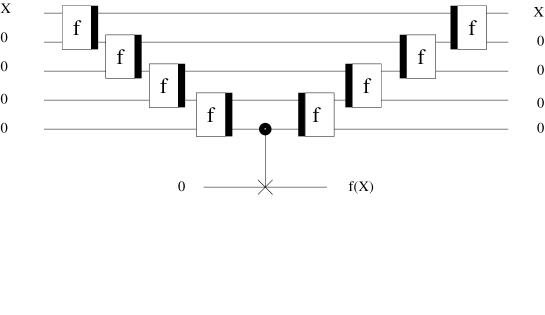
However, we have now generated three (middle) unwanted, garbage registers (see Fig. 8). We were only interested in computing and we do not need all the intermediate results. So, how do we re–set them to zero? We simply add another register and bitwise copy our result into it (this is accomplished by a CNOT); then we reverse the whole computation ending up with
| (23) |
This trick can be improved even further [13, 57], but these improvements are too detailed to be relevant here. The whole issue of reversibility becomes extremely important in constructing a network for Shor’s algorithm. However, before we analyse this, the biggest breakthrough in quantum computing we turn to a simpler example, Deutsch’s problem [34], which illustrates all the basic properties of quantum algorithms.
D Deutsch’s Problem
Deutsch’s problem is the simplest possible example which illustrates the advantages of quantum computation through exploiting entangled states. The problem is the following. Suppose that we are given a binary function of a binary variable . Thus, can either be or , and likewise can either be or , giving altogether four possibilities. However, suppose that we are not interested in the particular values of the function at and , but we need to know whether the function is: 1) constant, i.e. , or 2) varying, i.e. . Now Deutsch poses the following task: by computing only once determine whether it is constant or varying. This kind of problem is generally referred to as a promise algorithm, because one property out of a certain number of properties is initially promised to hold, and our task is to determine computationally which one holds (see also [28, 84] for other similar types of promise algorithms).
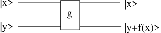
First of all, classically this is clearly impossible. We need to compute and then compute in order to compare them. There is no way out of this double evaluation. Quantum mechanically, however, there is a simple method to achieve this task by computing only once! Two qubits are needed for the computation. We can imagine that the first qubit is the input to the quantum computer whose internal (hardware) part is the second qubit. The computer itself will implement the following transformation on the two qubits
| (24) |
where is the input qubit and the hardware, as depicted in Fig. 9. Note that this transformation is reversible and thus there is a unitary transformation to implement it (but we will not pay any attention to that at the moment, as we are only interested here in the basic principle). Note also that has been used only once. The trick is to prepare the input in such a state that we make use of quantum entanglement. Let us have at the input
| (25) |
where is the actual input and is part of the computer hardware. Thus before the transformation is implemented, the state of the computer is in an equal superposition of all four basis states, which we obtain by simply expanding the state in eq. (25),
| (26) |
Note that there are negative phase factors before the second and fourth term. When this state now undergoes the transformation in eq. (24), we have the following output state
| (27) | |||||
| (28) |
where the bar indicates the opposite of that value, so that, for example, . This is an entangled state and now we see where the power of quantum computers is fully realised: each of the components in the superposition of underwent the same evolution of eq. (24) “simultaneously”, leading to the powerful “quantum parallelism” [26]. Let us look at the two possibilities now.
-
1.
if is constant then
(29) -
2.
if is varying then
(30)
Note that the output qubit (the first qubit) emerges in two different orthogonal states, depending on the type of . These two states can be distinguished with percent efficiency. This is easy to see if we first perform a Hadamard transformation on this qubit, leading to the state if the function is constant, and to the state if the function is varying. Now a single projective measurement in basis determines the type of the function. Therefore unlike their classical equivalents quantum computers can solve Deutsch’s problem.
It should be emphasised that this quantum computation, although extremely simple, contains all the main features of successful quantum algorithms: it can be shown that all quantum computations are just more complicated variations of Deutsch’s problem [22]. Deutsch’s algorithm has now been implemented successfully using nuclear magnetic resonance methods [48, 39]. Of course, the more complicated the computation, the more qubits involved, and the easier it is to see the difference between quantum and classical computations, especially the greater difference in their efficiency. The most striking example to date is Shor’s algorithm for the factorization of large numbers into primes, which we review next (there are other examples of quantum computation being faster than their classical counterpart, see e.g. [44], however none of them is as decisive as Shor’s algorithm).
IV Outline of Quantum Factorization
The algorithm for factorization dates back to the Ancient Greeks (the book by Knuth in [52] is a bible for algorithms, containing a number of important classical computational problems). It was probably known to Euclid, and it can be described simply as follows. We wish to find the prime factors of . This amounts to finding the smallest such that , where is chosen to be coprime to , i.e. so that and have no common divisors apart from . In other words, we want to determine the period of the function . Let us see how this works for, say, .
-
We choose a=2. Then obviously .
-
Next we compute modulo , and this gives .
-
This sequence is periodic with the period , which also satisfies .
-
Once is obtained we find the factors of N by computing , which in our case is .
Hence we have factorised into . Now this algorithm (or some of its close variants) can be implemented on a classical or on a quantum computer. To be able to compare their efficiency we need to know that there are two basic classes of problems:
-
1.
easy problems: the time of computation is a polynomial function of the size of the input , i.e. , where the coefficients are determined by the problem.
-
2.
hard problems: the time of computation is an exponential function of the size of the input (e.g. , where c is problem dependent).
The size of the input is always measured in bits (qubits). For example, if we are to factorize then we need bits to store this number. In general, to store a number N we need about , where the base of the logarithm is . (this is easy to see: just ask yourself how many different numbers can be written with bits). The easy problems are considered as computationally efficient, or tractable, whereas the hard problems are computationally inefficient, or intractable. Now the upshot of this discussion is that, for a given , there is no known efficient classical algorithm to factorise it. Let us illustrate how the simplest factorization algorithm performs: suppose that we want to determine the factors of by dividing it by , then then and so on up to . So the time of computation (which is in fact the number of elementary steps) is proportional to the number of divisions we have to perform, and this is , i.e. it is exponential. However, using a quantum computer and the above–described Euclid’s approach to factorization, we can factor any efficiently in polynomial time involving a linear number of qubits. This is essence of Shor’s algorithm.
There are two distinct stages in this algorithm [80] (for an extensive review of this algorithm see [33]). Initially, we have two registers (plus several other registers containing garbage, but these are irrelevant for explaining the basic principle of quantum factorization) at the input to the quantum computer. First, we prepare the first register in a superposition of consecutive natural numbers, while leaving the second register in state to obtain (as usual we omit the normalization)
| (31) |
where is some sufficiently large number. Now in the second register we compute the function . This can be achieved unitarily and the result is
| (32) |
Here again we see famous quantum parallelism in action. This completes the first stage of the algorithm and the trick now is to extract the period from the first register. To help us visualize this let us think of our previous example when and . Then we would have
| (33) | |||||
| (34) | |||||
| (35) |
Let us recall that we do not need to extract all the values of , but just the period of this function. This now sounds very much like Deutsch’s problem, where only the knowledge of a property of was important and not both its values. The solution is likewise similar, but is however much more computationally involved. Suppose that we now perform a measurement on the second register to determine its state. Suppose further that we obtain 4 as the result. The remaining state will be
| (36) |
so that the first register contains numbers repeating periodically with the period . This is now what we have to extract by manipulating the first register. To see how this works suppose for simplicity that divides exactly. For general and this state is
| (37) |
where and the second register is obviously irrelevant. Extracting involves performing a Fast Fourier Transform on the first register, so that the final state becomes
| (38) |
We can now perform a measurement in the basis where is an integer. Therefore, once we obtain a particular we have to solve the following equation where and are known. Assuming that and have no common factors (apart from ) we can determine by cancelling down to an irreducible fraction. Once is obtained we can easily infer the factors of .
In general, of course, Shor’s algorithm is probabilistic. This means that , and hence the factors of that we obtain by running the above quantum computation, might sometimes not be the right answer. However, whether the answer is right or wrong can be easily checked by multiplying the factors to get . Since multiplication is an easy computation this can be performed efficiently on a classical computer. If the result is not , we then repeat the whole Shor’s algorithm all over again, and we keep doing this until we get the right answer. Shor showed that even with this random element his algorithm is still efficient. In fact, the most time consuming part is the first one, where we have to obtain the state in eq. (32). Modular exponentiation takes of the order of elementary gates and this dominates the whole algorithm [94]. We should say that the memory space, i.e. the number of qubits needed for the entire computation, is of the order of . For completeness we state that all the above networks for addition, multiplication and exponentiation can be improved using standard computational techniques (see e.g. [3]), however, this improvement is not substantial and does not change the fundamental conclusion about the efficiency of quantum factorization.
All the computations we have considered thus far are “ideal” in the sense that every gate operation was assumed to be performed without error, and in addition states of qubits were completely preserved. In reality this is far from being the case. Quantum information is usually very fragile and easily undergoes errors deriving from the so called phenomenon of decoherence. Manipulating quantum information also presents a formidable experimental task. This is the subject of the remainder of our review.
V How to realize a Quantum Computer
In the previous sections we have seen that quantum computation is a fundamentally new concept that promises the solution of problems which are intractable on a classical computer. In this section we will now address the question of how to implement such a quantum computer in practise. The interest in the practical realization of a quantum computer increased substantially after the discovery of Shor’s factorization algorithm [80], which exhibited the great potential of quantum computation. An important question was whether a quantum computer required fundamentally new experimental techniques for its realization, or whether already known techniques would be sufficient. In fact, some of the early proposals for implementations of quantum computers had the disadvantage of using somewhat ’futuristic’ experimental techniques. Then, however, a very beautiful proposal for an ion-trap quantum computer was made by Cirac and Zoller [20] which employed only experimental methods which were already realized or which were expected to be realizable in the near future. Subsequently, other realistic suggestions such as quantum computation based on nuclear magnetic resonance methods have been made [24, 39, 51, 54]. Although these new proposals are very interesting, we confine ourselves here to the description of the linear ion trap implementation of Cirac and Zoller. The reason for this is that the ion trap quantum computer exhibits the basic ideas of quantum computation in a particularly transparent and beautiful way.
A The ion trap quantum computer
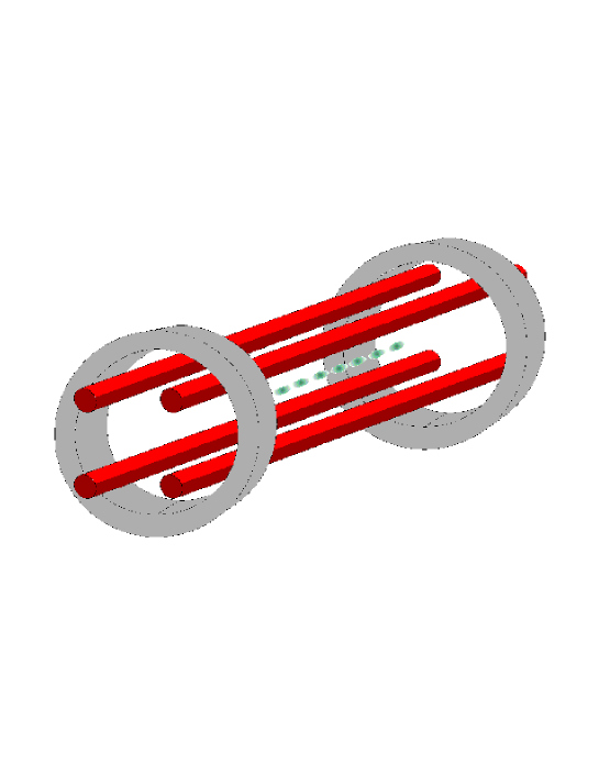
The basic experimental setup for an ion trap quantum computer is given in Fig. 10. In a linear ion trap ac currents in the electrodes generate a time dependent electric quadrupole field. Ions move in this potential and for suitable ac currents and ion masses, the ions are trapped. This means that they see an effective force towards the center of the axis of the linear ion trap. The equilibrium between the trapping force generated by the electrodes and the mutual electrostatic repulsion of the ions is given when the ions form a string where adjacent ions are separated by a few wavelengths of light. This separation is large enough to ensure that ions can be addressed individually by a laser. The idea of a linear ion trap is the same as that of a Paul trap [61] which is already being used to trap single ions for very long times. Linear ion traps are already working and it is possible to trap strings of ions or more in them [99]. However, no linear ion trap quantum computer with ions has been realized yet.
What is the reason for that. The practical problem with the implementation of the linear ion trap quantum computer is the mechanical degree of freedom of the ions. Although the ions are trapped along the axis of the linear ion trap they are not at rest, but oscillate around their equilibrium position. After having trapped the ions, the next step is then to cool them using methods of laser cooling which have recently been recognized by the Nobel Prize for physics [1, 47]. While it is fairly standard today to cool ions to temperatures of the order of millikelvin, it is very difficult to cool them to the necessary ground state of motion, i.e. to a state in which only the unavoidable motion due to the quantum mechanical uncertainty principle is present. A single ion has been cooled to its ground state of motion [60] some years ago, while two ions have been cooled to the ground state of motion while we were writing this review [100]. Experimentalists in this field are optimistic that it will soon be possible to cool a string consisting of a few ions to the ground state of motion.
As it is so difficult to cool the ions to the ground state of motion, we need to have a good reason to try it. To see why we want to cool the ions to the ground state of motion one should remember that we want to implement quantum gates between different qubits. In the ion trap, these qubits are localized and we cannot really move them from one place to another. If we want to implement a quantum gate between two ions that are separated, e.g. one at the beginning of the string and one at the end, then we need some ’medium’ that can be used for communication between these ions. Note that this communication is not classical but has to be quantum mechanical in nature as we want to establish quantum mechanical coherence between different ions. This communication is achieved by using the center-of-mass mode of the ions. If we excite the center-of-mass mode of the ions then all of the ions will oscillate in phase and therefore all of them will feel this oscillation simultaneously. This behaviour is illustrated in Fig. 11a. If the first ion is excited by a laser and the absorbed photon excites the center-of-mass mode then even the ion at the end of the chain will feel this. Therefore even distant ions can ’communicate’. In the next section we will explain how we can use the center-of-mass mode to generate a CNOT gate.
B The implementation of the CNOT gate
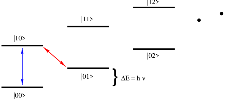
This idea of using the center-of-mass mode as a ’bus’ is the key ingredient in the ion trap quantum computer. It allows the implementation of two-bit gates such as a CNOT gate, for example. In the following we will explain how one can implement a CNOT gate in a linear ion trap computer. More complicated gates can be constructed, but as we pointed out in Section II a CNOT gate together with single-qubit rotations are sufficient to implement any unitary operation between quantum bits. Obviously single-qubit gates do not require the center-of-mass mode as a bus as they are implemented by manipulating a single ion with a suitably made laser pulse. In a CNOT gate it is essential that the two qubits (i.e.ions) interact and this is achieved by exciting the center-of-mass mode of all the ions in the linear ion trap. Therefore, before we describe how to implement a full CNOT gate, we explain briefly how we can excite the center-of-mass mode of the ions with a standing wave laser field. Let us first have a look at the energy levels of a single qubit and the center of mass mode which are given in Fig. 12. The vertical axis represents the energy of the joint system of ion and center-of-mass mode. The two levels on the far left are those with no phonons (i.e. excitations) in the center-of-mass mode. The lower state of the qubit is at energy zero, the upper state has energy where is the transition frequency between the qubit levels. The next two energy levels represent the energies of the qubit when one phonon has been excited in the center-of-mass mode. The energy required to excite the center-of-mass mode is and this is usually a very small energy compared to the energy required to excite the qubit. is of the order of MHz as compared to the transition frequency in a qubit which is of the order of . Before we give the Hamiltonian that describes the interaction between laser, ion and center-of-mass mode, we have a qualitative look at the dynamics of the system. Imagine that an ion is localized in a standing wave laser field. This laser drives the qubit transition in the ion. If the laser has a frequency (shown by a vertical blue arrow in Fig. 12) then the laser will most likely induce transitions between the lower and upper state of the qubit without affecting the center of mass mode. This is simply because all other transitions, e.g. the transition, are out of resonance. If, however, the frequency of the laser is (shown by a red arrow in Fig 12), then it predominantly generates transitions between the upper state of the ion and the vibrational state with excitations in the center-of-mass mode (state ) and the ground state of the ion and the vibrational state with excitations in the center-of-mass mode (state ). If both ion and center-of-mass mode are in the ground state, nothing at all happens. In summary we can see two effects. Firstly, a red detuned laser can change simultaneously the electronic state of the qubit and the state of the center-of-mass mode. Secondly the dynamics can be conditional on the internal state of the ion, i.e. the qubit. If the qubit is in the lower state then there is no dynamics, if not then the laser induces transitions. One can easily see that this would not be possible if the ions were not cooled to the ground state of the motion. If with high probability there is at least one phonon in the center-of-mass mode then the red detuned laser would always affect ions that are in the ground state.
This qualitative discussion neglects the importance of the position of the ion in the standing wave laser field. This is a very important factor, as it can be shown that an ion localized at the anti-node of the standing wave will, in leading order, interact with the laser without changing the excitation of the center-of-mass mode. If, on the other hand, the ion is localized at the node of the standing wave then in leading order both the internal degrees of freedom of the ion as well as the excitation of the center-of-mass mode are changed simultaneously. Qualitatively this can be understood in the following way. If the ion is at the anti-node of the field then it does not see any photons. Therefore in order to interact with the field it has to change position and therefore it either has to absorb or emit a photon. Hence a change in its internal degree of freedom always requires a change in the motional degree of freedom of the ion. If the ion is localized at the node of the field then it is not necessary for it to move in order to see photons. This qualitative reasoning can be corroborated by a precise derivation of the interaction Hamiltonian between ion, laser and center-of-mass mode. However, we refer the reader to the literature for this derivation [23] and only state the results here.
First we assume that the ion is localized at the node of the standing wave laser field of frequency . Then in leading order the Hamiltonian is given by
| (39) |
where is the number of ions that are in the linear ion trap, is the Rabi frequency of the laser, is the phase of the laser. The Lamb-Dicke parameter describes how well the ions are localized and are creation and annihilation operator for excitations in the center-of-mass mode. This Hamiltonian is an approximation and represents only the first term in an expansion of the true Hamiltonian in terms of . In addition, it neglects the interaction with other modes than the center-of-mass mode such as the one shown in Fig. 11b. These are good approximations as is much smaller than unity and because other modes of oscillation have resonance frequencies different from and are therefore out of resonance with the laser.
If the ion is localized at the anti-node of the standing wave laser field of frequency then the Hamiltonian is given by
| (40) |
The motional degree of freedom of the ions remains (in leading order) unchanged during the interaction with the laser. Again there will be higher order corrections in and off-resonant coupling terms to modes other than the center-of-mass mode.
Now let us see how we can implement a CNOT gate [20]. For simplicity we assume that we have only two ions in the linear ion trap, as the whole procedure generalizes easily to more ions. We split the procedure into two parts, as it then becomes more transparent. First we show how one can implement a controlled phase gate, i.e. a gate that flips the phase of the upper state of the target qubit only if the control qubit is in the upper state. Then we show that one can easily obtain a CNOT gate from this.
It is important that initially the center-of-mass mode is in the ground state. First we place the control qubit at the node of a standing wave laser filed. The interaction is described by the Hamiltonian Eq. (39). We apply the laser pulse on the control bit for a time so that it produces a -pulse. If in , describes the state of the control qubit, the state of the target qubit and the state of the center-of-mass mode then we find that the laser pulse has the following effect.
| (41) | |||||
| (42) | |||||
| (43) | |||||
| (44) |
Note that the action of the laser depends on the state of the control ion. If the control qubit is in the ground state then nothing happens, but if it is in the upper state then it goes to the ground state and simultaneously the center-of-mass mode is excited.
Now we manipulate the target qubit which we place at the node of a standing wave laser field. In this step we make use of the fact that in a real ion we have many atomic levels available. In Fig. 13 we see the qubit levels and and an additional energy level . We now couple the lower level of the qubit to the auxiliary level again using a Hamiltonian of the form Eq. (39) (only that we replace by ). We apply the laser for a time so that we effectively perform a full rotation. This means that no population at all ends up in level . The effect of this transition is that the ground state of the target bit flips its phase if the center-of-mass mode is excited. Therefore we obtain
| (45) | |||||
| (46) | |||||
| (47) | |||||
| (48) |
In the next step we apply again a pulse of duration to the control qubit using Hamiltonian Eq. (39). This results in the total transformation
| (49) | |||||
| (50) | |||||
| (51) | |||||
| (52) |
Therefore we have implemented a controlled phase gate. Now let us see why this transformation is really the basic building block for a CNOT gate. Consider the different set of basis states
| (53) |
If we rewrite the state of the target qubit in the basis Eq. (53) then the transformation Eq. (52) reads as
| (54) | |||||
| (55) | |||||
| (56) | |||||
| (57) |
This is the action of a CNOT gate. So, all we need to do is to rotate the basis of the target bit into the basis, then perform the controlled phase gate, and finally we rotate the basis back to . This generates a CNOT gate in the basis. The rotation between the basis sets can be achieved using the Hamiltonian Eq. (40), i.e. with a standing wave that has the target ion at its anti-node. For this we just have to chose the phase of the laser to be and perform a pulse, i.e. a pulse with the length . Going back from the basis to the basis is then done by a pulse. Therefore we are able to generate a CNOT gate as well as single qubit gates and this is all we need to implement any unitary transformation between qubits.
In our analysis we have made quite a number of simplifying assumptions some of which we have already mentioned. The Hamilton operators Eqs. (39,40) are only the leading order terms in an expansion with respect to the Lamb-Dicke parameter . In addition we have only taken into account the center-of-mass mode although there are many other modes that might also get excited. We also neglected any spontaneous emission from the ions and losses of excitations of the center-of-mass mode. That these are reasonable approximations can be seen most convincingly from the fact that a CNOT gate has been realized experimentally in an ion trap, albeit by a different scheme using only one ion [59]. In this realization the main source of noise was technical noise.
If we want to perform many quantum gates on many quantum bits then, however, the effect of errors will become much more serious. Therefore it is important to analyze the effect of noise on a quantum computer and to find ways to circumvent or correct them. This problem will be addressed in the next section.
VI Decoherence and Quantum Computation
In the last section we saw that in principle, we can implement a quantum computer in a linear ion trap. A single quantum gate has been demonstrated in this scheme [59] and it is expected that soon a few quantum gate operations will be performed on a few qubits. However, scaling up this implementation (i.e. implementing large numbers of quantum gates on many qubits) is not easy because noise from all kind of sources will disturb the quantum computer. Of course also a classical computer suffers from the interaction with a noisy environment and nevertheless works very well. The advantage of a classical computer is, however, that it is a classical device in the sense that one bit of information is represented by the presence or absence of a large number of electrons ( electrons for example). Therefore a small fluctuation in the number of electrons does not disturb the computer at all. On the contrary, in a quantum computer the qubit is stored in the electronic degree of freedom of a single atom. Even worse than that, a quantum computer crucially depends on the survival of quantum mechanical superposition states which are notoriously sensitive to decoherence and dissipation [101]. This makes a quantum computer extremely sensitive to small perturbations from the environment. It has been shown that even rare spontaneous emissions from a metastable state rule out long calculations unless new ideas are developed [64, 65, 66]. However, from classical information theory we know that it is possible to correct for errors by introducing redundancy [78]. Although initially there were doubts as to whether it would be possible to generalize these ideas to quantum mechanics, quantum error correction codes have been developed recently.
In this section we will give an example to illustrate how a quantum mechanical superposition state is very sensitive to noise using a special example of a noise process. Then we will discuss a general method that can be used to understand noise and its origin at the quantum level. Finally we explain the ideas of quantum error correction that have been developed to correct for the detrimental influence of noise in quantum computation.
A Decoherence of entangled states
To illustrate that entangled states are particularly sensitive to noise we assume that each two-level system interacts independently with the environment which is usually a very good assumption. The source of errors are so-called phase errors, represented by the operator
| (58) |
This means that if such an error occurs the phase of the ground state remains unchanged while the excited state flips its phase, i.e. and . Note that produces a discrete phase change. In reality we can find any arbitrary phase change given by the operator
| (59) |
However, the operator corresponding to this phase change can be reexpressed as a linear combination of the identity operator and the operator . Therefore the analysis using only is sufficient. A physical source of phase-noise can be that the ion that stores the qubit collides with atoms from the background gas. During this event usually no energy is exchanged but nevertheless the relative phase of states can be changed. We assume that the rate at which a single two-level system collides with atoms from the background gas is . If we prepare the qubit in a superposition state
| (60) |
then the relative phase will be randomized at a rate . After a time the state will have evolved into a statistical mixture
| (61) |
Now let us consider qubits. We assume that they are prepared in the state
| (62) |
In our error model, we observe that the relative phase of this highly entangled state is randomized at a rate that is much higher than . After a time the state is
| (63) |
when it is written in the basis basis. This accelerated randomization of the relative phase derives from the fact that an error in any one of the qubits switches the phase of the state Eq. (62). Therefore we have possibilities to destroy the phase which results in an effective decoherence rate of .
The state Eq. (62) is a particular example and not all states show the same sensitivity to decoherence. Nevertheless this example should make clear that a quantum computer is very sensitive to noise and, even worse, it becomes more and more sensitive to noise the larger the quantum computer becomes.
B A general error model
After this specific example of an error process, we will now consider a more general method to describe errors in qubits. In this description we take the state of the environment explicitly into account. In the example given above, that would mean that we keep track of the state of the background gas atom that has collided with our qubit. This is extremely difficult in practice but there is no physical principle that forbids it. In the following we will see that after an interaction with the environment the qubit becomes entangled with the environment. It is the fact that we do not have any knowledge about the environment that destroys the coherence of our quantum state. This description will also pave the way to the understanding of methods that are able to correct errors that are generated in a quantum states.
We assume that the initial state of our qubit is pure and that the environment is in the pure state . Initially the qubit and the environment are completely uncorrelated, i.e. the total state of the combined system is
| (64) |
Now, however, the qubit will interact with the environment. There are many possibilities, such as exchanging energy in the form of photons or the above mentioned phase errors due to collisions etc. In general the interaction with the environment is simply a joint unitary transformation between qubit and environment. Such a unitary transformation can be written in many different ways. A particularly useful way is via the Pauli spin operators which are of the form
| (65) |
After some time the total state of system and environment is then given by [32]
| (66) |
where stand for a unitary transformation acting on the state of the environment only. Note that we have four different errors represented by the operators . This stands in contrast to the classical case where we have only one sort of error, namely the bit flip . Every possible error is correlated to a specific state of the environment. So far we still have a pure state for the entire system including the environment and in principle it would be possible to recover the initial state of the qubit. Now, however, our ignorance of the state of the environment comes into play. Obviously, if we have no information about the state of the environment (which is usually the case) then we cannot find out what error has occurred and therefore we are unable to correct the error in the quantum state.
Now the question arises whether it is possible to correct errors that have occurred when we do not have access to the states of the environment! Is this possible at all? This question will be answered positively in the next subsection.
C Quantum error correction
In the previous subsection we have raised the question of whether we can correct errors in qubits as we can in classical communication and computation. Initially there were doubts that errors in quantum mechanical states can be corrected, but soon it become clear that this is in fact possible. The first quantum error correction code was discovered in 1995 by Shor [81] and later a more general theory of quantum error correction was developed [17, 32, 50, 86, 87]. This development has continued and has led to an avalanche of different codes that were optimized in different respects and adapted to special situations [9, 53, 56, 67, 93]. New mathematical techniques have been developed which are particularly suited to the study of quantum error correction codes [15, 17, 18, 19, 40, 41] [42, 43, 50, 70, 71, 72, 73] [74, 75, 83, 88].
How does quantum error correction work? Let us reconsider the example in subsection B where a qubit has been interacting with an environment. This interaction led to a correlation of the qubit with the environment, e.g. if the qubit collides with a background gas atom, their internal states become correlated. In principle such an error could be corrected if we could obtain complete knowledge of the joint state of the two systems. The fact that really makes it impossible to correct the errors is that we usually have no access to the information that is stored in the environment, e.g. the photon that has been emitted has not been detected by us. We do not know which error has occurred and therefore we are unable to correct it. So, we see that the source of irreversibility is the combination of entanglement of the qubit with the environment and the loss of information about the state of the environment.
How can we combat this loss of information? We could for example entangle our information-carrying qubit with some auxiliary qubits such that we can distribute the information about the information-qubit over many auxiliary qubits. To understand why this might work imagine the information qubit interacts with the environment and we have no access to the environment. Of course, the state of the qubit is now perturbed, but luckily this time we have some additional information about its original state in our auxiliary qubits that we can, unlike the environment, still access. The idea is now to correct the state of our qubit using this additional information. This is, in a very rough form, the idea of quantum error correction.
Now we present a simple example of a quantum error correction code that protects one qubit against the occurrence of a single amplitude error, i.e. the bit flip. Obviously, as just pointed out, we need additional qubits so that we can distribute over many qubits the information that was previously in the state of one qubit. In this case two additional qubits are necessary and sufficient. This amplitude error correcting code is presented in Fig. 14 where we have given the quantum network necessary to implement the quantum code and the subsequent error correction. This code has the property that it encodes the states into state and into state . A superposition is therefore encoded as . When the first bit is in the state and the second and third qubit are in the state then it is easily checked that this encoding is performed by the network on the left hand side in Fig. 14. After the encoding, one waits, and an error may occur during that time that is indicated by the box in Fig. 14. Subsequently we decode our state using two CNOT gates and then the error correction is performed in the last step using a Toffoli gate. Let us check whether the proposed method really works. Obviously when there has been no error at all then at the end the first qubit is recreated in the right state. What happens if the first bit suffers an amplitude error, i.e. it suffers the bit flip ? It is easy to see that before the application of the Toffoli gate the state of the three qubits will be . The second and third bit indicate that an error has occurred in the first qubit and the subsequent Toffoli gate corrects this error by flipping the first qubit. We can check that for errors in the second or third qubit the state just before the application of the Toffoli gate will be or . Therefore the Toffoli gate will leave the first bit unaffected. In conclusion we see that a single amplitude error can be corrected using the additional information about the environment stored in the auxiliary qubits. Note that we did not need to measure the state of the second and third qubit – all our encoding, decoding and error correction is performed by unitary transformations. Nevertheless at some point irreversibility catches us. Indeed if we want to reuse the two auxiliary qubits for the next round of quantum error correction then we have to prepare them in a standard state, e.g. the state . That means that we either have to dissipate irreversibly their energy to the environment, or we have to measure their state and then change their state by a unitary transformation.
On the other hand we could have done the error correction without the Toffoli gate. Instead we could perform a measurement of the state of the auxiliary quantum bits in the basis. If we find the state then we invert the first bit, otherwise we leave it unaffected. Finally have to reset the auxiliary bits to the ground state using a unitary transformation.
We have seen how to implement an amplitude error correcting code. But amplitude errors are not the only possible errors in quantum mechanics as we have already seen above – phase errors are a different possibility. Does the above code work when we have a phase error? A quick check reveals that the network given in Fig. 14 is not able to correct phase errors at all (Try it!). But one can easily change the network to allow the correction of phase errors. One just has to observe that the following relation holds
| (67) |
This means that if we consider a phase error ( operator) in a rotated basis then it appears as a amplitude error and vice versa. This new basis that we obtain from the by using a Hadamard transformation is given by and . In this new basis a phase error has the effect of an amplitude error, i.e. it has the effect . Therefore instead of encoding the state as shown above we encode it as
| (68) |
Therefore we obtain an phase error correcting code using a network as shown in Fig 15. This construction of the phase error correcting code from the amplitude error correcting code reveals an important principle that can be used to generate quantum error correcting codes that are able to correct one general error, i.e. one phase errors (), one amplitude errors () or a combination of both which is represented by the operator . If we want to achieve this, we need a code that, looked at in the basis, corrects amplitude errors and when written in the basis is also an amplitude error correcting code. Then the basic idea is first to check in the unrotated basis whether there has been an amplitude error. Then one rotates the state into the basis and again one checks whether in this basis we can find an amplitude error. Codes that have these properties can be found (although you need some knowledge of classical error correction). This approach can be found in much greater detail in [86, 87]. This approach is attractive, as it can be shown that one can construct quantum error correcting codes from classical error correcting codes. These ideas can be generalized to incorporate the most general quantum error correcting codes but for details of the mathematical principles behind this construction and actual examples we refer the interested reader to the literature [86, 87, 43]. It should also be noted that experimental progress has recently been made. Using a nuclear magnetic resonance implementation of a quantum computer the simple three bit code presented in subsection VI.C has been demonstrated recently [25].
So far we have seen that it is possible to use quantum error correction to correct errors that have occurred in a quantum bit. Errors will of course also appear during the operation of quantum gates. Therefore the question arises of what happens when errors appear during one of the quantum gates that are performed to generate the error syndrome and the subsequent error correction. Such an error can make the error correction fail and it would be important to establish whether it is possible to perform quantum error correction in a ’fault-tolerant’ form. Note also that an error during the operation of a two-bit gate may actually result in two errors. This can easily be seen at the example of a CNOT-gate. If the control-qubit suffers an amplitude error before the CNOT gate is performed then after the CNOT gate both the control and the target bit have suffered an amplitude error, (see Fig. 16) and check. Therefore errors during gate operations are particularly destructive and obviously methods have to be developed that avoids this multiplication of errors. In fact, such methods have been developed. However, they are quite involved and it would be beyond the scope of this article to review them. The interested reader is referred for details to the literature on fault-tolerant quantum computation [2, 42, 49, 82, 69, 89] and its special case of fault-tolerant quantum error correction [31].
VII Summary and Future Prospects
In this review we have seen that the laws of quantum mechanics imply a different kind of information processing to the traditional one based on the laws of classical physics. The central difference, as we emphasised, was in the fact that quantum mechanics allows physical systems to be in an entangled state, a phenomenon non-existent in classical physics. This leads to a quantum computer being able to solve certain tasks faster than its classical counterpart. More importantly, factorization of natural numbers into primes can be performed efficiently on a quantum computer using Shor’s algorithm, whereas it is at present considered to be intractable on a classical computer. However, to realize a quantum computer (or indeed any other computer) we have to have a physical medium in which to store and manipulate information. It is here that quantum information becomes very fragile and it turns out that the task of its storage and manipulation requires a lot of experimental ingenuity. We have presented a detailed account of the linear ion trap, one of the more promising proposals for a physically realizable quantum computer. Here information is stored into electronic states of ions, which are in turn confined to a linear trap and cooled to their ground state of motion. Laser light is then used to manipulate information in the form of different electronic transitions. However, the uncontrollable interactions of ions with their environment induce various errors known as decoherence (such as e.g. spontaneous emission in ions) and thus severely limit the power of computation. We have than shown that there is a method to combat decoherence during computation known under the name of quantum error correction. This then leads to the notion of fault tolerant quantum computation, which is a method of performing reliable quantum computation using unreliable basic components (e.g. gates) providing that the error rate in this components is below a certain allowed limit. Much theoretical work has been undertaken in this area at the moment and there is now a good understanding of its powers and limitations. The main task is now with the experimentalists to try to build the first fully functional quantum computer, although it should be noted that none of the present implementations appear to allow long or large scale quantum computations and a breakthrough in technology might be needed.
Despite the fact that at present large computational tasks seem to lie in the remote future, there is a lot of interesting and fundamental physics that can be done almost immediately with the present technology. A number of practical information transfer protocols use methods of quantum computation. One example is teleportation involving two parties usually referred to as Alice and Bob. Initially Alice and Bob share an entangled state of two qubits (each one having a single qubit) Alice then receives a qubit in a certain (to her unknown) state which she wants to “transmit” this state to Bob without actually sending the particle to him. She can do this by performing a simple quantum computation on her side, and communicating its result to Bob. Bob then performs the appropriate quantum computation on his side, after which his qubit assumes the state of the Alice’s qubit and the teleportation is achieved (for details see [14]). It should be noted that this experiment has been performed recently by a group in Innsbruck who achieved a successful teleportation of a singe qubit [8]. Again, since entangled states are non-existent in classical physics this kind of protocol is impossible, leading to another advantage of quantum information transfer over its classical analogue. An extension of this idea leads to more than two users, say , this time sharing entangled states of qubits. If each of the users does a particular quantum computation locally, and then they all communicate their results to each other, then more can be achieved than if they did not share any entanglement in the first place. This idea is known as distributed quantum computation and is currently being developed [21, 45]. There is a number of other interesting protocols and applications of quantum computation that have either been achieved or are within experimental reach , e.g. [16, 46]. We hope that quantum factorization and other large and important quantum computations will be realized eventually. Fortunately, there is a vast amount of effort and ingenuity being applied to these problems, and the future possibility of a fully functioning quantum computer still remains very much alive. En route to this realization, we will discover a great deal of new physics involving entanglement, decoherence and the preservation of quantum superpositions.
VIII Acknowledgements
. This work was supported in part by the European TMR Research Network ERB 4061PL95-1412, the European TMR Research Network ERBFMRXCT96066, a Feodor Lynen grant of the Alexander von Humboldt Stiftung, the EPSRC and the Knight trust. The authors would like to thank Peter Knight for helpful comments on the manuscript.
REFERENCES
- [1] C.S. Adams and E. Riis, Prog. Quant. Electr. 21, 1 (1997).
- [2] D. Aharonov and M. Ben-Or, e-print quant-ph/9611025.
- [3] A.V. Aho, J.E. Hopcroft and J.D. Ullman, Data Structures and Algorithms, Addison–Wesley (1983).
- [4] A. Barenco, Proc. R. Soc. Lond. A, 449, 679 (1995).
- [5] A. Barenco, C.H. Bennett, R. Cleve, D.P. DiVincenzo, N. Margolus, P. Shor, T. Sleator, J. Smolin and H. Weinfurter, Phys. Rev. A 52, 3457 (1995).
- [6] A. Barenco, A. Berthiaume, D. Deutsch, A. Ekert, R. Jozsa, and C. Macchiavello, SIAM J. Comp. 26, 1514 (1997).
- [7] A. Barenco, Cont. Phys. 37, 375 (1996).
- [8] D. Bouwmeester, J. W. Pan, K. Mattle, M. Eibl, H. Weinfurter, A. Zeilinger, Nature 390, 575-579 (1997).
- [9] S.L. Braunstein, e-print quant-ph/9711049.
- [10] J. S. Bell, Speakable and unspeakable in quantum mechanics (Cambridge Unicersity Press, 1987).
- [11] C. H. Bennett, IBM J. Res. Develop. 17, 525 (1973).
- [12] C.H Bennett, IBM J. Res. Dev. 32, 16 (1988).
- [13] C.H. Bennett, SIAM J. Comput. 18(4), 766 (1989).
- [14] C. H. Benett, G. Brassard, C. Crepeau, R. Jozsa, A. Peres and W. K. Wootters, Phys. Rev. Lett. 70, 1895 (1993).
- [15] C.H. Bennett, D.P. DiVincenzo, J.A. Smolin, and W.K. Wootters, Phys. Rev. A 54, 3824 (1996).
- [16] S. Bose, V. Vedral and P. L. Knight, Phys. Rev. A. 57, 822 (1998).
- [17] A.R. Calderbank and P.W. Shor, Phys. Rev. A 54, 1098 (1996).
- [18] A. R. Calderbank, E. M Rains, P. W. Shor and N. J. A. Sloane, e-print quant-ph/9608006.
- [19] A.R. Calderbank, E.M. Rains, P.W. Shor, and N.J.A. Sloane, Phys. Rev. Lett. 78, 405 (1997).
- [20] J.I. Cirac and P. Zoller, Phys. Rev. Lett. 74, 4091 (1995).
- [21] J.I. Cirac, A. Ekert, S.F. Huelga, and C. Macchiavello, in preparation.
- [22] R. Cleve, A. Ekert, C. Macchiavello, M. Mosca, Proc. R. Soc. A 454, 339 (1998).
- [23] C. Cohen-Tannoudji, J. Dupont-Roc, and G. Grynberg, Atom-Photon Interactions: Basic Processes and Applications, John-Wiley & Sons, Inc. New York, 1992.
- [24] D.G. Cory, M.D. Price, T.F. Havel, e-print quant-ph/9709001.
- [25] D.G. Cory, W. Mass, M. Price, E. Knill, R. Laflamme, W. H. Zurek, T.F. Havel, S.S. Somaroo, e-print quant-ph/9802018
- [26] D. Deutsch, Proc. R. Soc. Lond. A 400, 97 (1985).
- [27] D. Deutsch, Proc. R. Soc. Lond. A 425, 73 (1989).
- [28] D. Deutsch and R. Jozsa, Proc. R. Soc. Lond. A 439, 553 (1992).
- [29] D. Deutsch, A. Barenco and A. Ekert, Proc. R. Soc. Lond. A 449 669 (1995).
- [30] D. Deutsch, The Fabric of Reality (Viking–Penguin Publishers, London, 1997).
- [31] D.P. DiVincenzo and P.W. Shor, Phys. Rev. Lett. 77, 3260 (1996).
- [32] A. Ekert and C. Macchiavello, Phys. Rev. Lett. 77, 2585 (1996)
- [33] A. Ekert and R. Jozsa, Rev. Mod. Phys. 68, 733 (1996).
- [34] A. Ekert, From quantum-codemaking to quantum-codebreaking, lanl gov e-print server no. 9703035 (1997).
- [35] R. P. Feynman, Int. J. Theo. Phys. 21, 467 (1982).
- [36] R. P. Feynman, Found. Phys. 16, 507 (1986).
- [37] R. P. Feynman, Feynman’s Lectures on Computation (Addison-Wesley Publishing Company, Inc., 1996).
- [38] E. Fredkin and T. Toffoli, Int. J. Theo. Phys. 21, 219 (1982).
- [39] N.A. Gershenfeld and I.L. Chuang, Science 275, 350 (1997).
- [40] D. Gottesman, Phys. Rev. A 54, 1862 (1996).
- [41] D. Gottesman, Phys. Rev. A 56, 76 (1997).
- [42] D. Gottesmann, e-print quant-ph/9702029.
- [43] D. Gottesmann, e-print quant-ph/9705052.
- [44] L. K. Grover, Phys. Rev. Lett. 79, 325 (1997).
- [45] L.K. Grover, e-print quant-ph/9704012.
- [46] S.F. Huelga, C. Macchiavello, T. Pellizzari, A.K. Ekert, M.B. Plenio, and J.I. Cirac, Phys. Rev. Lett. 79, 3865 (1997).
- [47] W.M. Itano, J.C. Bergquist, J.J. Bollinger, and D.J. Wineland, Phys. Scripta T59, 106 (1995).
- [48] J. A. Jones and M. Mosca, Implementation of a Quantum Algorithm to Solve Deutsch’s Problem on a Nuclear Magnetic Resonance Quantum Computer, submitted to J. Chem. Phys (1998), also e-print quant-ph/9801027.
- [49] P.L. Knight, M.B. Plenio and V. Vedral, Phil. Trans. R. Soc. London 355, 2381 (1997).
- [50] E. Knill and R. Laflamme, Phys. Rev. A 55, 900 (1997).
- [51] E. Knill, I. Chuang, R. Laflamme, e-print quant-ph/9706053.
- [52] D.E. Knuth, The Art of Computer Programming, Volume 2: Seminumerical Algorithms (Addison-Wesley, New York, 1981).
- [53] R. Laflamme, C. Miquel, J.P. Paz, and W.H. Zurek, Phys. Rev. Lett. 77, 198 (1996).
- [54] R. Laflamme, E. Knill, W.H. Zurek, P. Catasti, S.V.S. Mariappan, e-print quant-ph/9709025.
- [55] R. Landauer, IBM J. Res. Dev. 5, 183 (1961).
- [56] S. Lloyd and J.J.E. Slotine, e-print quant-ph/9711021.
- [57] R.Y. Levine and A.T. Sherman, SIAM J. Comput. 19(4), 673 (1990).
- [58] S. Lloyd, Phys. Rev. Lett. 75, 346 (1995).
- [59] C. Monroe, D.M. Meekhof, B.E. King, W.M. Itano, and D.J. Wineland, Phys. Rev. Lett. 75, 4714 (1995).
- [60] C. Monroe, D.M. Meekhof, B.E. King, S.R. Jefferts, W.M. Itano, D.J. Wineland and P. Gould, Phys. Rev. Lett 75, 4011 (1995).
- [61] W. Paul, Rev. Mod. Phys. 62, 531 (1990).
- [62] ’The physics of quantum information’, Editors D. Bouwmeester, A.K. Ekert and A. Zeilinger, Proceedings of the TMR network meeting on quantum information theory, Almagro (1997).
- [63] M. Plenio, V. Vedral and P.L. Knight, Phys. World 9, 19 (1996).
- [64] M.B. Plenio and P.L. Knight, Phys. Rev. A 53, 2986 (1996).
- [65] M.B. Plenio and P.L. Knight, Proc. R. Soc. Lond. A 453, 2017 (1997).
- [66] M.B. Plenio and P.L. Knight, New Developments on Fundamental Problems in Quantum Physics, edited by M. Ferrero and A. van der Merwe 1997 (Kluwer, Dordrecht), p. 311.
- [67] M.B. Plenio, V. Vedral, and P.L. Knight, Phys. Rev. A 55, 67 (1997).
- [68] M.B. Plenio, V. Vedral, and P.L. Knight, Phys. Rev. A 55, 4593 (1997).
- [69] J. Preskill, e-print quant-ph/9712048.
- [70] E.M. Rains, e-print quant-ph/9612015.
- [71] E.M. Rains, e-print quant-ph/9611001.
- [72] E.M. Rains, R.H. Hardin, P.W. Shor, and N.J.A Sloane, Phys. Rev. Lett. 79, 953 (1997).
- [73] E.M. Rains, e-print quant-ph/9704043.
- [74] E.M. Rains, e-print quant-ph/9704042.
- [75] E.M. Rains, e-print quant-ph/9703048.
- [76] A. Schoenhage and V. Strassen, Computing 7, 281 (1971).
- [77] B. Schumacher, Phys. Rev. A 51, 2738 (1995).
- [78] C. E. Shannon and W. Weaver, The Mathematical Theory of Communication, (University of Illinois Press, Urbana, IL, 1949).
- [79] H. M. Sheffer, Trans. Am. Math. Soc. 14, 481 (1913).
- [80] P.W. Shor, in Proceedings of the 35th Annual Symposium on the Theory of Computer Science, edited by S. Goldwasser (IEEE Computer Society Press, Los Alamitos, CA), p.124 (1994).
- [81] P.W. Shor, Phys. Rev. A 52, 2493 (1995).
- [82] P.W. Shor, e-print quant-ph/9605011.
- [83] P.W. Shor and R. Laflamme, e-print quant-ph/9610040.
- [84] D.S. Simon, Proceedings of the 35th Annual Symposium on the Foundations of Computer Science, edited by S. Goldwasser (IEEE Computer Society Press, Los Alamitos, CA), 16 (1994).
- [85] Special issue of Scientific American entitled “Solid state century” (December 1997).
- [86] A.M. Steane, Phys. Rev. Lett. 77, 793 (1996).
- [87] A.M. Steane, Proc. R. Soc. Lond. A 452, 2551 (1996).
- [88] A.M. Steane, Phys. Rev. A 54, 4741 (1996).
- [89] A. Steane, Phys. Rev. Lett. 78, 2252 (1997).
- [90] A.M. Steane, Rep. Prog. Phys. , (1998).
- [91] L. Szilard, Z. Phys. 53, 840 (1929).
- [92] T. Toffoli, Math. Systems Theory 14, 13 (1981).
- [93] L. Vaidman, L. Goldenberg, and S. Wiesner, Phys. Rev. A 54, 1745 (1996).
- [94] V. Vedral, A. Barenco and A. Ekert, Phys. Rev. A 53, 154 (1996).
- [95] V. Vedral, M. B. Plenio, M. A. Ripppin and P. L. Knight, Phys. Rev. Lett. 78, 2275 (1997).
- [96] V. Vedral, M. B. Plenio, K.A. Jacobs and P. L. Knight, Phys. Rev. A 56, 4452 (1997)
- [97] V. Vedral, M.A. Rippin and M.B. Plenio, J. Mod. Optics 44, 2185 (1997)
- [98] V. Vedral and M. B. Plenio, Phys. Rev. A 57, (1998).
- [99] I. Waki, S. Kassner, G. Birkl, and H. Walther, Phys. Rev. Lett. 68, 2007 (1992).
- [100] D.J. Wineland, presented at the NASA meeting on quantum computation at Palm Springs, February 1998.
- [101] W.H. Zurek, Phys. Today 44, 36 (1991).